


Vibration Measurement Basic Parameters
Do you notice why Vibration Measurement is so important? Many plants are in the process of changing their philosophy from that of shutting down a plant on a time scheduled basis to that of running the plant until the condition of the machinery indicates, it is time to shut down.
This condition is, of course, determined by instrumentation. This “predictive maintenance” philosophy is particularly applicable where the rotating machinery is the limiting factor in a plant maintenance schedule. Obviously this type of predictive maintenance program requires dependence upon instrumentation, and the proper interpretation of the data it provides. In this respect, it is important that all available parameters of vibration and rotor position are measured and evaluated. A simple investigation of amplitude and frequency alone does not, and will not, provide sufficient information about machinery performance to provide a strong, accurate predictive maintenance program.
Pleas check also: VIBRATION MONITORING SYSTEM
The following is a discussion of basic dynamic motion (vibration) and rotor position parameters that should be measured and analyzed in the diagnosis of rotating machinery in predictive maintenance programs;
DYNAMIC MOTION VIBRATION PARAMETERS
Amplitude
Amplitude of vibration on most machinery is expressed in peak-to-peak mils displacement. Amplitude, whether expressed in displacement, velocity, or acceleration, is generally an indicator of severity. It attempts to answer the question, “Is this machine running smoothly or roughly?”. The ability to measured the shaft with proximity probes has helped greatly in providing more accurate information with regard to the amplitude of the vibration. Today, most continuous monitoring of critical machinery is provided with a peak-to-peak displacement measurement either in mils or micrometers.
Frequency
The frequency of vibration (cycle per minute) is most commonly expressed in multiples of rotative speed of the machine.
It also provides an easy means to express the frequency of vibration. It is necessary only to refer to the frequency of vibration in such terms as one times rpm, two times rpm, 43% of rpm etc, rather than having to express all vibration in cycle-per-minute or hertz.
SYSTEM POWER UP INHIBIT (3300 Series)
The system monitor provide a power up inhabit function that allows each monitor to inhibit its alarms during power up or whenever a system voltage falls below its operating level. After power up, the inhibit function remains active for approx. 2 seconds.
SUPPLY VOLTAGE OKInput supply is 110/220 50Hz. We are using here 110 50Hz option and obtaining different outputs which are,
0/P voltage = -18 VDC (9000 series)
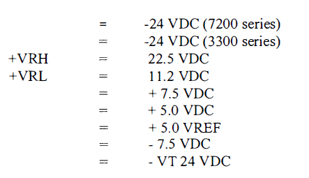
Seven LEDs located behind the front panel of the system monitor are ON to indicate when above mention supply voltages are functioning. Then a green LED on the front panel (Supplies OK) will lit.
SYSTEM RESET
The system monitor provide system reset capability that is activated by either external contact closer through terminals on the power input module or by pressing the RESET switch on the front panel.
TRIP MULTIPLY
It is activated by contact closure through terminals on the power input module. When activated, trip multiply allows the alarm set points to be multiplied by a factor preset on monitors with trip multiply option installed. The trip multiply function is indicated by a red led on the front panel.
Please check also: Vibration Rod drop measurement
OK RELAY
The system monitor drives an OK RELAY that is located on the power input module. The SPDT relay is used to indicate that the 3300 rack is in ok condition. The ok relay is set normally energized. The ok relay is deactivated either by the system power up inhibit signal from system monitor or by a not ok signal from the monitor.
ALARM SET POINT ADJUST
The system monitor has two switches on the front panel that adjust set point levels on each monitor. One switch is for upscale adjustments and the other is for down scale adjustments.