Rolling Element Bearing Frequencies Derivation of Bearing Frequencies


The topic is about Rolling Element Bearing Frequencies Derivation of Bearing Frequencies.Primary Rolling Element Bearing Frequencies. Cage Frequency. Race Ball Pass Frequency.

Rolling Element Bearing Frequencies

These calculated frequencies are essentially of academic interest, because (1) it frequently occurs that any flaw on any element rapidly generates secondary flaws on other elements and (2) knowledge of the existence and extent of a flaw is vital; however, the element that it is on is not too important because the entire rolling element bearing is normally replaced and not just the damaged portion.

Rolling element bearings find many uses in today’s machinery. They can be found in motors, slow-speed rollers, gas turbines, pumps, and many other machines. Some of the reasons rolling element bearings are used are: low starting friction, low operating friction, ability to support loads at low (even zero) speed, lower sensitivity to lubrication (compared to fluid film bearings, thus a simpler lubrication system can often be used), and the ability to support both radial and axial loads in the same bearing. When some of these factors are important, rolling element bearings may be in use.


By themselves, rolling element bearings have very little damping, so whenever a machine with rolling element bearings traverses a balance resonance, large vibration can result. Also, compared to fluid film bearings which generally have a long life, rolling element bearings have a limited fatigue life due to the repeated stresses involved in their normal use.

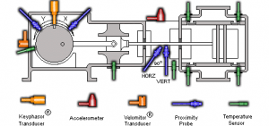
Rolling element bearings, regardless of type (ball, cylindrical, spherical, tapered, or needle) consist of an inner and outer race separated by the rolling elements, which are usually held in a cage (see Figure.

Rolling Element Bearing Frequencies

Mechanical flaws may develop on any of these components. Using the basic geometry of a bearing, the fundamental frequencies generated by these flaws can be determined.

For most applications, the outer race is fixed and does not rotate. However, in some instances, just the outer race or both races rotate. For the case of the outer race fixed, Following figure contains a summary of the main bearing frequencies. These frequencies may, and often do, include sum and difference frequencies. Often they are modulated by the speed of the equipment.

Rolling Element Bearing Frequencies

Read more

What is REBAM How the REBAM Concept Works and Field Application of REBAM

How the REBAM Concept Works and Field Application of REBAM

Introduction
The ability to monitor and analyze machinery utilizing rolling element bearings is a unique challenge. Most monitoring and analysis techniques used today use a casing vibration instrumentation system to determine rolling element bearing condition. Due to problems introduced by either the instrumentation itself or by interference for extraneous vibration, limited success has been achieved. The purpose of this applications note is to outline how vibration measurements made directly at the bearing outer ring, which contains the outer race, can greatly improve the ability to monitor and analyze rolling element bearing condition.

How the REBAM Concept Works

The concept of measuring the deflections of a rolling element bearing outer ring during operation was originally demonstrated by Shapiro of the Franklin Institute using strain gages attached to the bearing’s outer ring. This concept was further improved upon by G. J. Phillips of the David W. Taylor Naval Research and Development Center using noncontact fiber optic techniques. Bently Nevada Corporation adopted this noncontact concept and, as an alternative to the fiber optic sensor, developed a high-gain, low-noise eddy current proximity transducer to measure the deflections of a rolling element bearing’s outer ring. This transducer is called REBAM®, which is an acronym for Rolling Element Bearing Activity Monitor.

A high-gain eddy current proximity transducer is mounted through the bearing housing observing the external surface of the bearing outer ring (Figure 1). The bearing outer ring contains the bearing’s outer race. During bearing operation, the bearing’s outer ring deflects minutely as a function of applied forces. The REBAM® transducer measures the very small (microinch/micrometre) deflections are measured in terms of displacement and are typically in the range of 2 to 300 microinces (0.5 to 8 micrometres). Under typical operating conditions, the signal from a good bearing, observed on an oscilloscope, displays a smooth signal with few or no “spikes” of significant amplitude. When an internal bearing flaw (e.g. , inner race, outer race, rolling elements) is present, “spikes” of significant amplitude occur on the vibration signal (Figure 2). In order to clarify how the REBAM® signal can be used to evaluate rolling element bearing condition, some discussion of rolling element bearing vibration characteristics is justified.

What is REBAM

How the REBAM Concept Works

Rolling Element Bearing Vibration Characteristics
The vibrations produced by machines with rolling element bearings occur in three frequency regions: (1) Rotor Vibration region, (2) Prime Spike (element passage) region and (3) the High Frequency region. The High Frequency region measurement (above 5 Khz) is for specialized applications and will not be discussed in this applications note.

1. Rotor Vibration Region

Rotor-related vibration normally occurs in the range of 1/4 to 3 times shaft rotative speed (1/4Xx – 3x) and, when using the REBAM® instrumentation system, is measured in terms of displacement. Many rolling element bearing failures are the direct result of a rotor-related malfunction (e.g., unbalance, misalignment, or rotor instability). If the rotor-related vibration data is not monitored for identification and correction of rotor-related malfunctions, the bearing will chronically fail.

2. Prime Spike (Element Passage) Region
The second vibration frequency region to monitor for machines with rolling element bearings is the Prime Spike (element passage) region. A classical characteristic of rolling element bearings is the generation of specific frequencies based on the bearing geometry, number of rolling elements and the speed at which the bearing is rotating. These “bearing-related” frequencies are generated even by a new bearing, but the amplitudes are very small. Prime Spike is a term used by Bently Nevada to describe a vibration frequency range which includes those bearing frequencies that are generated by the rolling elements traversing either an inner or outer race flaw. This frequency range is normally 1 to 7 times the Outer Race Element Passage rate (1-7EPx). The Outer Race Element Passage rate (EPx) is defined as the rate at which the rolling elements pass a point on the outer bearing race.

Read more

Eddy Current Proximity Probes for Overspeed Protection Systems

Eddy Current Proximity Probes for Overspeed Protection Systems

Introduction
Since overspeed is one of the most dangerous conditions that can occur in a turbine, it is essential that overspeed protection systems are properly installed. In the sections below are issues you should consider when applying eddy current proximity transducers in an overspeed protection system.

A diagram shows the terms used in this document for describing gear geometry.

Signal Amplitude at Overspeed
The signal from a transducer system viewing a gear is a complex signal. In other words the signal may contain a vibration and/or runout component as well as the speed component in following figure. Other signal variations could come from inconsistencies in gear tooth dimensions. Normally these components of the signal are small compared to the speed component of the signal. However, when a machine approaches overspeed there must be no doubt which component of the signal represents the speed of the gear.

Signals from the transducer may contain a vibration and/or runout signal as well as a speed signal.

In order to insure that the speed signal is the dominant signal component, we recommend that the amplitude of the speed signal be greater than 7 Vpp at the overspeed setpoint (200 mV/mil transducer system).

The signal amplitude at overspeed is dependent on factors such as probe gap, gear dimensions, target material, and signal frequency. The general approach to estimating signal amplitude at overspeed is:


  1. Find the amplitude of the speed signal at slow roll.
  2. Estimate the amount of signal attenuation at the overspeed setpoint (frequency response).

Since the geometry of the gear affects both the slow roll signal amplitude and signal attenuation, the next section describes three types of gear geometry and shows the typical signal produced by each type.

Read more

error: Content is Protected.