Standardized Rules for Measurement on Rotating Machinery
Introduction In order to better understand the behavior or rotating machinery, it is most desirable to standardize communication by means of a set of recommended practices defining the polarity and phase referencing of transducers, data storage and data presentation techniques.
This set of transducer orientation and polarity recommendations has been informally developed by machinery engineers and gradually standardized by Bently Nevada Corporation for its customers’ convenience. These recommendations are formulated to remove various possible ambiguities and are fully independent of the direction of rotation, dynamic impedance and dynamic action of the machine.
Non-contacting Relative Displacement
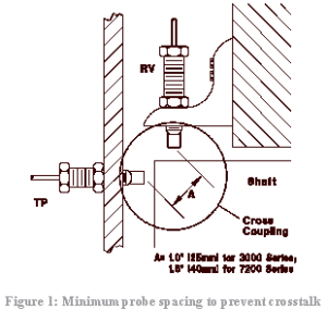
Motion toward the transducer along its sensitive axis shall produce a positive (+) magnitude of voltage or current. The polarity of a relative displacement transducer such as the Bently Nevada proximity probe is easily tested by decreasing gap as shown in Figure 1. The gap can be decreased by either moving the probe towards the observed material, or by moving the observed material towards the probe. Use of a Bently Nevada TK 3 is highly recommended.
Inertially referenced Displacement, Velocity and Acceleration
The polarity of Inertially referenced displacement, velocity or accelerometer transducers is easily tested by means of a tap test. The tap test consists of lightly tapping the transducer in its sensitive axis. The resulting timebase waveform, as shown in Figure 2, is an initially positive (+) going output signal when tapped toward the sensitive axis.
Transducers and Instrumentation for Vibration Measurement and Monitoring of Rolling Element Bearings
1. REBAM Instrumentation System
Rolling Element Bearing Activity Monitor. The REBAM system uses a high-gain, low-noise eddy current proximity transducer that is installed in the bearing housing observing the bearing outer ring.
The bearing outer ring contains the outer race. The REBAM® transducer measures the very small (microinch/micrometre) deflection of the outer ring as the rolling elements pass the area observed by the transducer. These deflections are measured in terms of displacement. The operating frequency range for the REBAM® transducer system is from 0 Hz (dc) to 10 kHz (0 to 600 kcpm). The REBAM® system is a direct and very sensitive method of rolling element bearing measurement. It offers a very high signal-to-noise ratio, as compared to casing-mounted acceleration or velocity measurements.
Through the use of electronic filters, the REBAM® vibration signal is separated into Rotor Vibration and Prime Spike regions as previously discussed. Typical Prime Spike amplitudes are 10 to 50 microinches (0.25 to 1.3 micrometres) for a good bearing and 2 to 5 times that for a damaged bear-ing. However, the amplitude of the REBAM® signal is highly dependent upon the amount of loading on the elements as they pass the location of the probe, and it is, therefore, not possible to give broad guidelines for a healthy or a damaged bearing. A common practice is to take readings on what is known to be a healthy bearing and set the monitor Alert and Danger alarm levels at 1.5 and 2 times the baseline level. Field and lab tests confirm that using such alarm levels provides adequate failure protection.
2. Casing Vibration Instrument Systems Rolling element bearing condition can be monitored by using casing measurements. Overall velocity or displacement, Prime Spike velocity, and the high frequency acceleration regions can be used. Bently Nevada can provide accelerometer or velocity transducer-based systems to monitor rolling element bearing condition. Overall casing velocity or displacement provides a means for determining the general mechanical condition of rolling element bearing machinery.
For a velocity transducer-based system, the frequency range used is from 10 Hz to 1 kHz (600 cpm to 60 kcpm). For an accelerometer-based system, the frequency range used is from 10 Hz to 20 kHz (600 cpm to 1.2 million cpm). Depending on the machine speed, the velocity system frequency range is likely to span the Rotor frequency region and the lower end of the Prime Spike frequency region. The acceleration system will cover the Rotor frequency region, Prime Spike region, and into the high frequency region.
As stated previously, the Prime Spike region is used by Bently Nevada to monitor the rolling element bearing-related frequencies (inner/outer race defects). By filtering out the rotor-related vibration signals (i.e., 1X, 2X, etc.), it is possible to get better signals related to the rolling element bearing condition. The Prime Spike frequency region includes thefundamental element passage frequency (EPx) and harmonics up to 7 EPx.
Predictive Maintenance through the Monitoring and Diagnostics of Rolling Element Bearings
Introduction The predictive maintenance philosophy of using vibration information to lower operating costs and increase machinery availability is gaining acceptance throughout industry. Since most of the machinery in a predictive maintenance program contains rolling element bearings, it is imperative to understand how to monitor and diagnose problems associated with them. Bently Nevada has adopted a two-part philosophy with regard to rolling element bearing monitoring and diagnostics: (1) the monitor system will provide adequate warning to avert catastrophic machine failures and (2) diagnostic data will be available so that when warning is given, the bearings will have visible damage. This philosophy should be kept in mind during the following discussion.
Rolling Element Bearing Characteristics Any discussion of monitoring and diagnostics for rolling element bearings would not be complete without a comparison with the techniques used for fluid film bearings. The construction of a fluid film bearing is such that the shaft is supported by a fluid film during operation. By design, the shaft can experience motion relative to the bearing. Because of this freedom of motion, the industry-accepted vibration measurement for a fluid film bearing machine is a shaft relative measurement, i.e., proximity probe.
A rolling element bearing, by design, has extremely small clearances which do not allow a significant amount of shaft motion relative to the bearing (Figure 1).
Forces from the shaft are transferred through the rolling elements to the bearing outer race and then ultimately to the bearing housing. Because of this transmission, a casing (bearing housing) measurement is normally acceptable for monitoring machines with rolling element bearings. However, as explained later in this discussion, a method called REBAM® is available from Bently Nevada Corporation that allows vibration measurements directly at the bearing outer ring, which contains the outer race. This direct measurement greatly enhances bearing vibration data, and in some cases, this is the only measurement that can provide adequate vibration information.(Reference Hansen, J. Seven and Harker, Roger G., ”A New Method for Rolling Element Bearing Monitoring in the Petrochemical Industry,” Presented at the Vibration Institute Seminar, New Orleans, Lousiana, June 1984.) Shaft relative vibration measurements (i.e., proximity probe) are also useful when clearances increase during failure and for observation of rotor problems that are not related to bearings. A classical characteristic of rolling element bearings is the generation of specific vibration frequencies based on the bearing geometry, number of rolling elements and the speed at which the bearing is rotating Click to lik to read terms of frequencies in vibration. (Reference Foiles, Bill, “Rolling Element Bearing Frequencies,: Edited by Bently Nevada Corporation.)
The most prominent of these characteristic bearing frequencies are the Outer Race Element Pass frequency, Inner Race Element Pass frequency, Element Spin frequency, and the Fundamental Train frequency or Cage frequency. These vibrational components are generated even in a new bearing, but the amplitudes are small. Bently Nevada defines the frequency range from the Outer Race Element Pass frequency (1EPx) to seven times this value (7EPx) as the Prime Spike frequency region. This range contains the Inner and Outer Race Element Pass and Element Spin frequencies, and is therefore a valuable region to monitor bearing condition. The Cage frequency lies below 1/2 rotor speed (for a stationary outer ring) and cage damage would therefore show up in the Rotor frequency region, defined below. Distinguishing between these two regions enhances the ability to determine if a vibration increase is caused by a failing bearing or a rotor-related malfunction (imbalance, misalignment, fluid induced instability, etc.). It should be kept in mind that, from a plant manager’s point of view, it is much more important to determine when a bearing needs to be replaced to avert a machine failure and unnecessary downtime, than it is to determine what components within the bearing are being damaged. The primary goal of a rolling element bearing monitoring system is to satisfy this need. The secondary goal is to provide data that is appropriate for diagnosing the failure of the bearing with the purpose of determining the root cause (improper mounting, lubrication, loading, etc.) so that similar failures can be avoided in the future.