1. GENERAL
………………………………………………………………..
1.1
Summary
1.2
References
1.3 Conflicts
………………………………………………………………
1.4
Deviations
1.5
Document Availability
1.6 General Requirements for Vendor Data Submittals ……1.7
Submittals Required with Bid Documents
1.8
Submittals Required after Purchase Order Award and
Prior to Fabrication ………………………………………………….
1.9
Items Requiring Owner Inspector’s Approval Prior to
the Start of Fabrication
1.10 Submittals Required for Project Documentation
1.11 Owner’s Review Of Fabricators Documents ……………..2. PRODUCTS
2.1 Materials
2.2
Fabrication Tolerances – Criteria of Acceptability ……….
2.3
Bend Ovality – Criteria of Acceptability
2.4 Minimum Wall Thickness – Criteria of Acceptability
2.5 Hardness Limits – Criteria Of Acceptability …………………2.6
Heat Treatment Requirements for Pipe Bends
3. EXECUTION
3.1 General Fabrication Requirements ………………………….3.2 Qualification of Bending Procedures
3.3
Hot Bending – Extent of Production Testing and
Inspection Required
3.4
Cold Bending – Extent of Production Testing and
Inspection Required ………………………………………………4. ATTACHMENTS
1. General
1.1 Summary
1.1.1 Scope of Specification
1.1.1.1 This specification is applicable to all cold and hot bending procedures used to form bends in
carbon steel, Cr-Mo steel, and austenitic stainless steel pipe.
1.1.1.2 Use of bends shall be limited to the extent established by contract documents.
1.1.2 Terminology
The following terms are defined as follows, unless otherwise indicated:
Owner. “Owner” refers to the owner of the piping installation, or the owner’s assigned representative.
Fabricator. “Fabricator” refers to the entity to which the contract has been given for the fabrication of piping
in accordance with this and referenced specifications.
Bend Radius. ‘Bend Radius’ refers to the actual bend centerline radius.
Actual Bend Centerline Radius = Nominal Pipe Diameter X Specified Bend Radius
Bisecting Angle: The mid point of the bend (45 on a 90 bend)
Extrados. “Extrados” refers to the outside arc of the bend (the outer radius).
Intrados. ‘Intrados’ refers to the inside arc of the bend (the inside radius).
Neutral Axis. ‘Neutral Axis’ refers to that portion of the pipe or tube that is neither in tension or
compression.
O.D ‘O.D.’ refers to the outside diameter of the pipe or tube.
Tangent. The straight section of material on either side of the arc of a bend.
Tangent Point. The point at which the bend is started or ended.
Transition Zone. The area, at the tangent points of a bend, that covers the change (transition from
unheated to heated material.
Wrinkles/Buckles. Definite folds, creases, or crinkles formed on the surface of the pipe during the bending
operation.
1.2 References
The publications listed below form part of this specification. Each publication shall be the latest revision
and addendum in effect on the date this specification is issued for construction, unless noted otherwise.
Except as modified by the requirements specified herein, Work included in this specification shall conform
to the applicable provisions of these publications.
American Society of Mechanical Engineers (ASME)
B31.1 Power Piping
B31.3 Chemical Plant and Petroleum Refinery Piping
American Society for Testing and Materials (ASTM)
ASTM A262 Detecting Susceptibility to Intergranular Attack in Stainless Steels
ASTM A370 Methods and Definitions for Mechanical Testing of Steel Products
Piping Fabrication Institute (PFI)
Standard ES3
Standard ES24
1.2.1 Where fabrication criteria in this specification is affected by city, county, state, or federal
requirements, this specification shall be modified as necessary to ensure compliance.
1.3 Conflicts
Where conflicts appear between standard specifications, isometric drawings, and the content of this
document, the Fabricator shall immediately inform the Owner’s Procurement representative of the conflict
prior to proceeding. In general, the order of precedence is isometrics, bills of material, standards, this
document.
1.4 Deviations
All fabrication, material specifications, testing, inspection, and documentation shall be in strict accordance
with this document and its attachments. All official correspondence, requests for approval to deviate from
specifications and drawings, and proposed material substitutions shall be in writing (fax or letter form) and
shall be forwarded to the Owner’s procurement representative. The Owner’s procurement representative
shall coordinate the responses and submit them to a central person at the Fabricator’s office.
1.5 Document Availability
All documents pertaining to this project shall be made available at any time upon request.
1.6 General Requirements for Vendor Data Submittals
All documents submitted must be in reproducible form suitable for microfilming, and shall indicate that they
have been checked prior to submittal to the Owner. All documents must be submitted in accordance with
submittal instructions and requirements provided to the Fabricator.
1.7 Submittals Required with Bid Documents
1.7.1 Statement of Bending Capability of Fabricator. The Fabricator’s bid proposal shall include a history
that is adequate to demonstrate the extent of their experience and success in making bends, meeting all
specifications stated herein, for the pipe materials, sizes, schedules, and bend radii included in this scope
of work. The Fabricator shall make available, upon Owner’s request, test reports and other supporting
documents substantiating these statements.
1.7.2 Schedule of Anticipated Wall Thinning. The Fabricator’s bid proposal shall include a schedule stating
the maximum anticipated wall thinning for all materials, pipe sizes, bend radii, and bending processes
applicable to the defined scope of work.
1.7.3 Statement of Required Tangent Lengths. The Fabricator’s bid proposal shall include a statement of
required tangent lengths necessary to accommodate their bending equipment. In the event that longer
tangent lengths are necessary to avoid mismatch due to ovaling at field weld locations, these
recommended lengths shall be stated.
1.7.4 Statement Regarding the Availability of Bending Procedures and Bending Procedure Qualification
Records. The Fabricator’s bid proposal shall include a statement confirming the availability of Bending
Procedures and Bending Procedure Qualification Records conforming to the requirements of this
specification. In the event that Procedure Qualification Records are not available covering the stated scope
of bending, the Fabricator shall make clear the extent of Procedure Qualification Records available, and
the intent to complete additional Procedure Qualifications as required by this specification, prior to the
beginning of Fabrication. Any additional costs chargeable to the Owner that are associated with such
activities must be clearly defined in the bid proposal.
Important:
It is required that the Fabricator provide Bending Procedure Qualification Records for each combination of
material, diameter, wall thickness, and radius being bent. Exceptions to this requirement are not permitted
without the Owner’s written approval. Additional costs incurred by the Fabricator to meet these
requirements will not be accepted by the Owner without written agreement completed prior to the award
and acceptance of the Purchase Order.
1.7.5 Statement Regarding the Availability of Bending Machine Operator Performance Qualification
Records. The Fabricator’s proposal shall include a statement concerning the availability of Performance
Qualification Records for benders who will perform work for the Owner. These records shall be maintained
in the Fabricator’s files and shall be available at any time for review by the Owner’s inspectors.
1.7.6 Definition of Essential Variables.The Fabricator’s bid proposal shall contain documents defining the
essential variables and their established tolerances for both Induction and Cold Bending procedures.
1.7.7 Testing Requirements for Qualification of Bending Procedures. The Fabricator’s bid proposal shall
contain a table which comprehensively defines the testing requirements necessary to qualify the
Fabricator’s bending procedures. The table shall clearly define the type of tests required, and the locations
at which the tests are conducted (e.g., extrados, neutral axis, intrados, transition zone, tangent, etc.).
1.7.8 Method of Monitoring Hot Bending Temperatures. Hot Bending temperatures shall be monitored from
the start of the bend and throughout the completion of the bend. The method by which temperatures are
monitored and the locations at which readings are taken shall be stated in the proposal.
1.8 Submittals Required after Purchase Order Award and Prior to Fabrication
The following shall be submitted for approval upon receipt of the Purchase Order and prior to the
commencement of fabrication.
a. Quality Control Report Forms
The quality control report forms are those forms on which the results of inspection activities are
recorded. The forms shall list all types of inspection required as well as the required inspection
locations.
b. Fabricator’s General Bending Specification
The General Bending Specification is that specification which is controls all of the Fabricator’s
bending related activities. This specification shall address the following items:
(i) General quality control procedures, including a general check list of bending related activities,
including in-process quality control procedures and tests
(ii) A statement of receiving inspections required for each length of pipe to be bent.
(iii) A statement of methods by which the following are confirmed: material specification, grade,
chemical composition, mechanical properties, wall thickness, and visual inspection for defects
(iv) Bend Procedure Qualification Test Table
(v) This table is a matrix defining the types of tests required for qualification of each Bending
Procedure, and the specific locations on the bend at which these tests are performed.
c. Bending Procedure Qualification Records
Each combination of material, diameter, wall thickness and radius must be qualified. Pre-qualified
procedures are acceptable if the material used for qualification is equivalent to that of the pipe to be
bent.
1.9 Items Requiring Owner Inspector’s Approval Prior to the Start of Fabrication
Bending Procedures
1.9.1 Bending Procedures required by the scope of work shall be available in the Fabricator’s facility for
review by the Owner’s inspector. The Bending Procedures must be approved by the Owner’s inspector
prior to start of fabrication.
1.9.2 The Bending Procedure shall include the following information, with all essential variables so
designated:
a. Specific information as to the make and model of the bending equipment.
b. Bending process utilized (cold, hot, induction, automatic, manual, etc.).
c. Pipe materials, sizes, and schedules for which the procedure is applicable.
d. Orientation requirements for loading of piping for bending.
e. Bending temperature limits and monitoring requirements.
f. Quench medium, quench rates, and quench rate control methods.
g. Bending speed limits and monitoring requirements.
h. Heat treatment requirements and methods.
i.
In-process quality control inspection and documentation requirements.
j. Wall thinning tolerance based on initial measured thickness.
k. Fabricator shall state any recommended restrictions regarding the use of EFW or other welded
piping, based on their experience and the limitations of their equipment and procedures.
1.10 Submittals Required for Project Documentation
Copies of the documentation listed below shall be provided to the Owner by the Fabricator upon request,
otherwise such data shall be made available to the Owner’s representative at any time throughout the
course of the project and up to one year afterward. All reports shall be traceable to the applicable pipe
spool.
1.10.1 Certificate of Conformance. The Fabricator shall provide a Certificate of Conformance, signed by
the Fabricator’s authorized representative (preferably the Inspector), stating that all bends conform to, and
have been fabricated, inspected, and tested in accordance with the requirements of this and all referenced
specifications.
1.10.2 Completed Quality Control Forms. Completed Quality Control Forms shall be maintained at all times
by the Fabricator.
1.10.3 Inspection Reports. All production inspection and testing, and the required locations of such
activities, shall be shown on these forms.
1.10.4 Heat Treating Reports and Charts. Heat treating reports and charts shall be made available upon
request.
1.11 Owner’s Review Of Fabricators Documents
The Owner’s review of Fabricator’s documents does not relieve the Fabricator of the responsibility for
completeness, accuracy, and compliance to codes, specifications, and other requirements.
2. Products
2.1 Materials
2.1.1 Conformance. All materials shall conform to the referenced standards and specifications. The use of
material having a wall thickness exceeding that specified by the Owner is permissible only when written
permission is granted by the Owner. Material markings shall be maintained at all times.
2.1.2 Material Purchased by the Fabricator. The Fabricator shall not purchase materials to be used for
bends prior to confirming that approved equipment and methods are sufficient to assure minimum wall
thickness requirements established for this contract.
2.1.3 Hot Bent Stainless Steel Pipe. Hot bent stainless steel pipe shall be furnished in the solution
annealed condition.
2.2 Fabrication Tolerances – Criteria of Acceptability
The fabrication tolerances shall be in accordance with PFI Standard ES3. When closer tolerances are
required, they shall be noted on the piping drawings. The following additional tolerances apply:
Radius of Bend: +/- 1.0%
Degree of Bend: +/- 0.5 Degree
Plane of Bend: +/- 1.0 Degree
Flat Plane of Bend: +/- 1.0% of Centerline Radius
2.3 Bend Ovality – Criteria of Acceptability
2.3.1 Ovality shall be within the limits established by the applicable ASME piping code. Note special
limitations established by ASME piping codes for piping designed for vacuum conditions. Other ovality
limits required for pigging operations, etc. shall be indicated on the piping isometrics.
2.3.2 Ovality at field weld connections shall not result in mismatch with adjacent piping.
2.4 Minimum Wall Thickness – Criteria of Acceptability
Bending shall not result in a measured wall thickness at any point in the bend that is less than that
described below.
2.4.1 The minimum measured wall thickness is acceptable when it exceeds any of the following
criteria:
a. The wall thickness established by deducting from the specified nominal wall thickness, the miltolerance applicable to the specified piping material.
b. The wall thickness established by deducting from the nominal wall the amount of anticipated
thinning agreed upon in the purchase order.
2.4.2 When the minimum measured wall thickness is less than that established by the above criteria, the
Fabricator shall perform calculations necessary to establish required wall thickness in accordance with thapplicable ASME piping code, and shall submit the calculations and the minimum measure wall thicknesfor Owner review and approval. The use of design conditions assigned to an individual line as the basis fodetermining the minimum acceptable wall thickness is permissible only with written approval from the
Owner.
2.4.3 All minimum wall thickness measurements must meet the minimum mechanical thickness
requirements established by the Owner.
2.5 Hardness Limits – Criteria Of Acceptability
Maximum hardness shall be as follows:

2.6 Heat Treatment Requirements for Pipe Bends
2.6.1 Heat treatment shall conform to the requirements of the applicable piping code (ASME B31.1,
Paragraph 129.3; or ASME B31.3, Paragraph 332.4). Particularly note heat treating requirements required
for cold bends in materials requiring impact testing.
2.6.2 Stress relief heat treatments may be used to restore required properties to bends. Stress relief heattreatments shall be in accordance with those of the pipe material purchasing specification or, if the
specification does not include heat treatment, the governing ASME piping code.
3. Execution
3.1 General Fabrication Requirements
3.1.1 Applicable Piping Codes. Bending, inspection, and testing shall conform to the requirements of the
applicable piping code referenced in the piping material specifications (ASME B31.1 or ASME B31.3).
Refer to the Line Class Index to determine the applicable ASME piping code. Additional requirements, of
this document and referenced standards and specifications shall also apply.
3.1.2 Orientation of Welds.When bending welded pipe, the pipe shall be loaded in such a manner as to
maintain the weld as close as possible to the neutral axis, and always within 15 of the neutral axis. This
requirement shall be followed to the greatest extent possible on multi-plane bends.
3.1.3 Circumferential Welds.Circumferential welds shall not be present within the arc of the bend or within
the tangent length on either end.
3.1.4 Grinding to Remove Wrinkling / Buckling Resulting from Bending. It is not permissible to grind
wrinkles / buckles resulting from bending without the approval of the Owner’s inspector.
3.1.5 Owner Responsibility for Failed Bending Attempts. The Owner shall be charged only for bends
delivered to and accepted by the Owner. Materials, labor, and other charges associated with bends that fail
to meet the requirements of this and referenced documents shall not be charged to the Owner. Extra welds
required to replace such bends shall not be charged to the Owner.
3.2 Qualification of Bending Procedures
3.2.1 General
3.2.1.1 The Fabricator shall qualify Bending Procedures by making the required type of test bends, and
fulfilling the required testing procedures. The results shall be recorded in the Bending Procedure
Qualification Record. All pipe bending procedures shall be qualified before starting production bending.
3.2.1.2 Qualification testing shall demonstrate that the bending procedure does not degrade the bent
portion of the pipe.
a. The material in the bend shall be shown to satisfy the elongation and hardness limitations, and notch
toughness requirements (if any) of the pipe material purchase specification.
b. Sectioning of the bend shall demonstrate that the bending process does not cause injurious flaws such
as cracks.
3.2.2 Extent of Testing Required
3.2.2.1 The types of tests and the locations at which the tests are performed shall conform to the “Bend
Procedure Qualification Test Table” submitted in accordance with Paragraph 1.8.b.4 of this document, as
well as any additional requirements established by contract documents.
3.2.2.2 In the event that any one test fails to meet the acceptance criteria, a complete set of all tests
required to qualify the Bending Procedure shall be performed for each new bend attempt.
3.2.2.3 The Bending Procedure must be requalified when a change is made in any of the essential
variables, beyond the limits established for this contract.
3.2.3 Types of Tests
3.2.3.1 Tension. Tensile testing is used to determine yield strength, tensile strength, and elongation
properties of the base metal and weld metal in both the bend and tangent areas.
a. Tensile properties shall be determined in accordance with ASTM A370. Specimen orientation
(transverse or longitudinal) shall be as specified in the applicable material specification.
b. One (1) specimen shall be tested from each location specified on the “Bend Procedure
Qualification Test Table”. Successful qualification requires that each specimen tested meets the
required yield strength, tensile strength, and elongation specified by the applicable ASTM or ASME
material specification. Yield strength shall be determined by the 0.5% extension under load method.
3.2.3.2 Notch Toughness. Charpy impact tests are used to determine the notch toughness of the base
metal and the weld metal in both the bend and tangent areas.
a. Notch Tensile properties shall be determined in accordance with ASTM A370. Three (3) full size
(when possible) Charpy Type “A” V-Notch specimens from each location shall be tested. The axis of
the specimen shall be transverse to the axis of the material, and the notch perpendicular to the
surface.
b. The acceptance criteria and test temperatures shall be as specified in the material specification.
Any additional toughness requirements dictated by the applicable ASME piping code (B31.3, etc.)
shall also apply.
3.2.3.3 Hardness. Hardness tests are used to determine the hardness of the base metal, weld, and heat
affected zone in the areas of the bend, transition zone, and tangent areas. Hardness tests performed on
the bend surface shall be performed using Rockwell, Brinell, or other Owner approved methods. Hardness
tests of welds and heat affected zones shall be performed using microhardness Vickers or Knoop scales.
3.2.3.4 Susceptibility to Intergranular Corrosion. For stainless steel bends, the susceptibility to
intergranular attack associated with the precipitation of chromium carbides is tested in accordance with
ASTM A262, Practices “A” and “E”.
3.3 Hot Bending – Extent of Production Testing and Inspection Required
Visual examination, hardness testing, thickness testing, ovality measurements, and all other testing and
inspection requirements shall conform to the following requirements as well as those established in the
Owner approved General Bending Specification (reference Paragraph 1.8.b).
3.3.1 Frequency of Production Testing
3.3.1.1 The minimum acceptable level of production testing is as established in this document.
3.3.1.2 Unless otherwise specified under the test type, at least the first five production bends of each
bending procedure used, during each bending operator’s shift, shall be tested. Following five consecutive
acceptable readings, 10% of the subsequent bends shall be tested to the same level as the first five
bends. The failure of any bend to qualify shall result in 100% checking of all bends produced after the last
successful 10% check.
3.3.2 Visual Examination
All bends shall be examined visually over 100% of their area for laminations, cracks, notches, gouges, or
other such injurious defects. Surface imperfections may be removed by grinding provided that the
remaining wall thickness is within the limits established by this specification. Wrinkles (buckling) shall not
exceed the limits established by PFI ES24, and shall not be ground without written permission.
3.3.3 Liquid Penetrant Inspection. Liquid penetrant inspection shall be performed on 100% of the Chrome
Moly bends. Testing shall be performed on 100% of the extrados half of each of these bends.
3.3.4 Ovality Measurements. Ovality shall be measured at the bend start, 1/4, mid, 3/4, and finish points
(ie, on each of the quadrants). Frequency shall be as specified in Paragraph 3.3.1.
3.3.5 Wall Thickness Testing. Wall thickness measurements shall be taken by ultrasonic examination. Wall
thickness shall be measured on the extrados at three locations; one reading at the mid point (bisecting
angle), and one reading on each end of the bend at a location one to six inches from the point of tangency
(on the bend side of the tangent point). Frequency shall be as specified in Paragraph 3.3.1.
3.3.6 Hardness Testing:
3.3.6.1 If the carbon or low alloy pipe purchasing specification indicates hardness or notch toughness
requirements, or places a limit on the maximum yield or tensile strengths, production hardness testing
shall be required.
3.3.6.2 Hardness measurements (total 6) shall be taken at the locations specified below. Frequency shall
be as specified in Paragraph 3.3.1.
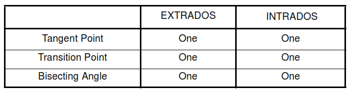
Note. Additional test locations may be specified for post bend heat treated materials with longitudinal welds
having filler metal added, or for bends used in services in which the material is susceptible to stress
corrosion cracking.
3.3.7 Shop Pressure Testing
Shop pressure testing is not required except as dictated in individual cases.
3.4 Cold Bending – Extent of Production Testing and Inspection Required
Visual examination, hardness testing, thickness testing, ovality measurements, and all other testing and
inspection requirements shall conform to the following requirements as well as those established in the
Owner approved General Bending Specification (reference Paragraph 1.8.b).
3.4.1 Frequency of Production Testing
3.4.1.1 The minimum acceptable level of production testing is as established in this document.
3.4.1.2 Unless otherwise specified under the test type, at least the first five production bends of each
unique combination of pipe size, wall thickness, bend radius, and material that is bent during each bending
operator’s shift shall be tested.
Following five consecutive acceptable readings, 10% of the subsequent bends shall be tested to the same
level as the first five bends. The failure of any bend to qualify shall result in “two for one” testing as follows:
a. For each reject, test two additional bends having the same material, wall thickness, and bend
radius. The two additional bends tested shall have been produced on the same day, by the same shift
operator, and with the same machine set-up.
b.
If no defects are found in the additional two bends tested, no additional testing is required beyond
resumption of the normal testing rate. If defects are found in either bend, a second set of two bends
(same selection criteria as first set) must be tested.
c.
If no defects are found in the second tested set of two bends, no additional testing is required
beyond resumption of the normal testing rate. It defects are found in either bend of the second set,
100% of all bends having the identical selection criteria shall be tested.
3.4.2 Visual Examination. All bends shall be examined visually over 100% of their area for laminations,
cracks, notches, gouges, or other such injurious defects. Surface imperfections may be removed by
grinding provided that the remaining wall thickness is within the limits established by this specification.
Wrinkles (buckling) shall not exceed the limits established by PFI ES24, and shall not be ground without
written permission.
3.4.3 Liquid Penetrant Inspection. This requirement shall be specified in the additional technical notes of
the purchase order.
3.4.4 Ovality Measurements. Ovality shall be measured at the bend mid point. Frequency shall be as
specified in Paragraph 3.4.1.
3.4.5 Wall Thickness Testing. Wall thickness measurements shall be taken by ultrasonic examination. Wall
thickness shall be measured on the extrados at three locations; one reading at the mid point (bisecting
angle). Frequency shall be as specified in Paragraph 3.4.1.
3.4.6 Hardness Testing:
3.4.6.1 If the carbon or low alloy pipe purchasing specification indicates hardness or notch toughness
requirements, or places a limit on the maximum yield or tensile strengths, production hardness testing
shall be required.
3.4.6.2 Hardness measurements (total 4) shall be taken at the locations specified below.
Frequency shall be as specified in Paragraph 3.4.1, except that only 5% testing is required after the first
five acceptable consecutive readings.
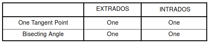
Note. Additional test locations may be specified for post bend heat treated materials with longitudinal
welds having filler metal added, or for bends used in services in which the material is susceptible to stress
corrosion cracking.
3.4.7 Shop Pressure Testing
Shop pressure testing is not required except as dictated in individual cases.