1. Scope ……………………………………………………….
2. References ……………………………………………………….
3. Definitions ……………………………………………………….
4. General Requirements ……………………………………………………….
4.1. Design Limitations …………………………..
4.2. Gasket Types ……………………………………………………….
4.3. Material Limitations …………………………..
4.4. Service Limitations …………………………..
5. Design Limitations ……………………………………………………….
5.1. Gasket Dimensions …………………………..
5.2. Gasket Thickness …………………………..
5.3. Flat Face Flanges …………………………..
5.4. Gasket Application …………………………..
5.5. Single Gasket ……………………………………………………….
5.6. Gaskets For Wellhead Piping …………………………..
6. Gasket Types & Selection …………………………..
6.1. Sheet or Cut Gaskets (Flat Ring ) …………………………..
6.2. Laminated Sheet Goods …………………………..
6.3. Spiral Wound Gaskets…………………………..
6.4. Corrugated Gaskets …………………………..
6.5. Ring Joint Gaskets …………………………..
6.6. Proprietary Designs gaskets …………………………..
6.7. Gasket Selection…………………………..
7. Material Limitations ……………………………………………………….
7.1. Sheet Gasket Material …………………………..
7.2. Corrugated Gaskets …………………………..
7.3. Spiral Wound Gaskets…………………………..
7.4. Ring Joint Gaskets …………………………..
8. Service ……………………………………………………….
8.1. High Temperature …………………………..
8.2. Low Temperature …………………………..
8.3. Acid Service ……………………………………………………….
8.4. Caustic Service ……………………………………………………….
8.5. Flat Faced Flanges …………………………..
8.6. Plastic Flanges ……………………………………………………….
9. Gasket Thickness ……………………………………………………….
9.1. Compressed Gaskets …………………………..
9.2. Spiral Wound Gaskets…………………………..
10. Flange Isolation Kits ……………………………………………………….
11. Flange Facings ……………………………………………………….
11.1. Contact Surface Finish …………………………..
12. Purchase Description for Gaskets…………………………..
13. Revision History………………………………………
1. Scope
This standard supplements ASME B 31.1, ASME B31.3, ASME B31.4 and ASME B31.8 codes
and defines mandatory requirements governing the selection of gaskets for flanged joints.
In case of conflict between the requirements specified herein and those stipulated elsewhere in
other SES and international codes and standards; the most stringent requirements shall govern.
2. References
Reference is made in this standard to the following documents. The latest issues, amendments,
addendums and supplements to these documents shall apply unless otherwise indicated.
SABIC Engineering Standards (SES)
P28-G01 Pipe Joints
P25-G01 Selection of Flanges
Z01-G04 Measurement Units for Use in SABIC Projects
American Petroleum Institute (API)
6A Specification for Wellhead and Christmas Tree Equipment
American Society of Mechanical Engineers (ASME)
B16.1 Cast Iron Pipe Flanges and Flanged Fittings
B16.5 Pipe Flanges and Flanged Fittings
B16.20 Metallic Gaskets for Pipe Flanges – Ring Joint, Spiral-wound, and Jacketed
B16.21 Nonmetallic Flat Gaskets for Pipe Flanges
B16.47 Large Diameter Steel Flanges
B31.1 Power Piping
B31.3 Process Piping
B31.4 Pipe Line Transportation systems for liquid hydrocarbons and other liquids
B31.8 Gas Transmission and Distribution Piping Systems
B46.1 Surface Texture(Surface roughness, waviness and lay)
Section VIII, Div 1 Boiler and Pressure Vessel Code
American Society for Testing and Materials (ASTM)
D 1418 Standard Practice for Rubber and Rubber Latices – Nomenclature
Manufacturers Standardization Society
SP-6 Standard Finishes for Contact Faces of Pipe Flanges and Connecting-End Flanges of
Valves and Fittings
Process Industry Practices
PIP PNSM0105 Purchasing Requirements for gaskets
3. Definitions
For the purpose of understanding this standard the following definitions apply.
Ring Gasket. A flat gasket in the shape of a ring, to fit a raised face or flat face.
Ring Joint Gasket. A ring with an oval, or octagonal section for use with ring joint flanges.
4. General Requirements
4.1. Design Limitations
4.2. Gasket Types
4.3. Material Limitations
4.4. Service Limitations
5. Design Limitations
5.1. Gasket Dimensions
Gasket dimensions are determined by the flange that the gaskets are intended to fit. The gasket
face is shown in the appropriate flange standards, as discussed in P25 -G01.
5.2. Gasket Thickness
The gasket thickness is usually determined by the gasket type. Some types are available in
more than one thickness, for the sake of matching existing inline dimensions. These types are
discussed with the gasket type.
5.3. Flat Face Flanges
Flat face flanges, with full face gaskets shall be used when one or both of the mating flanges in
a joint is ASME B16.1. Class 125 gray cast iron, aluminum, or plastic, may be over-stressed by
bearing against a raised face. Adapter rings may be necessary, in some cases, to level-off the
surface, for mating equipment. These rings may be described as gaskets.
5.4. Gasket Application
Gaskets shall be suitable for the intended service and compatible with the flange facing, the
strength of the flange, and bolting.
5.5. Single Gasket
Not more than one gasket shall be used between mating surfaces.
5.6. Gaskets For Wellhead Piping
Octagonal, pressure energized Type R, low carbon steel ring joint gaskets per API 6A shall be
used with API 6A Type 6B flanges. Type BX gaskets per API 6A shall be used with Type 6BX
flanges.
6. Gasket Types & Selection
This section describes the various types of gaskets.
6.1. Sheet or Cut Gaskets (Flat Ring )
These gaskets may be purchased as “cut”, as ring gaskets, or in sheet form to be custom cut as
needed. Cut gaskets may be supplied in segmented form, for large sizes. Cut gaskets may be
used for flat face, raised face, or tongue and groove faces. Dimensional standard for nonmetallic
flat
gaskets
shall
be
as
per
ASME
B16.21.
6.2 Laminated Sheet Goods
The sheet goods are of a laminated design, using a stainless steel foil sandwiched between two
sheets of flexible graphite. This material is made in two forms:
a. Flat metal
b. With tangs punched into the metal that “key the flexible graphite to the metal, making the
design less prone to blowout.
6.3 Spiral Wound Gaskets
6.3.1 Windings
Spiral wound gaskets have alternating metal, and filler wound into a tight spiral. As the
flanges are tightened the metal windings deform into such a shape which acts as a spring
pushing on both flanges. The filler seals the joint.
6.3.2 Centering Ring
All Spiral wound gaskets shall be furnished assembled into a centering ring. The centering is
carbon steel as a standard, that is painted, metal plated or otherwise coated to inhibit
atmospheric corrosion. The thickness, of centering ring shall be as per ASME B 16.20. This
centering ring acts as a gauge to seat the gasket. The flanges are tightened until they contact
the ring. Cold service use a stainless steel ring.
6.3.3 Inner Ring
Inner rings keep the windings from extruding into the pipe. Highly erosive services also benefit
from inner rings. The material of inner ring shall be stainless steel unless otherwise specified.
Research has shown that inner rings are useful in the following sizes.
a. NPS 26 and larger sizes for ASME pressure Classes 150 and 300
b. NPS 14 and larger sizes for ASME pressure Class 600 & 900
c. NPS 12 and larger sizes for ASME pressure Class 1500.
d. Cryogenic services of temperature -45 deg C and below
e. High Temperature services of temperature above 427 ºC
f. For all PTFE filler gaskets.
g. Polymer fluid service.
h. Dimensional standard for Spiral wound gaskets shall be as per ASME B16.20.
6.4 Corrugated Gaskets
Corrugated gaskets are stamped from sheet metal, with concentric corrugations on the seating
surface. As the flanges are tightened, the corrugations deform, and act like a spring loaded seal.
Dimensional standard for Corrugated gaskets shall be as per ASME B16.20.
6.5 Ring Joint Gaskets
A metallic ring with an oval or octagonal section for use with ring joint flanges and it is generally
used for High pressure services. The dimensional standard for Ring joint gaskets shall be as per
ASME B16.20.
6.6 Proprietary Designs gaskets
There are several companies making proprietary designs. There are designs that use a
combination of corrugations and a filler material. There are also envelope types that use a very
good resilient filler, with a TFE cover, for use in very corrosive services.
6.7 Gasket Selection
The Gasket selected shall be in accordance with the following criteria:
6.7.1 Spiral wound Gasket shall be adopted in all piping line classes up to 600 class rating in
process hydrocarbons, corrosive and steam services. However, flat ring gasket may be used
only in category-D fluid services subject to approval from SABIC.
6.7.2 Full face gaskets, shall be used when one or both of the mating flanges made of Gray cast
iron, Aluminum, FRP or Plastic.
6.7.3 Ring Joint gasket (octagonal ring) shall be adopted in all piping line classes having 900 rating
and above. However, the use of Ring joint gasket is also permissible in piping line classes of
below 900 class rating if Ring joint type flange facing is specified.
7 Material Limitations
7.1 Sheet Gasket Material
7.1.1 Compressed Fiber
The most common type of sheet material is compressed fiber. Natural and synthetic fibers are
used. The fibers are held in place with a binder, which also aids in sealing. The binder is the
component that will limit the use of the gasket. The binder will limit temperature. The binder
will have limited chemical resistance.
7.1.2 Elastomers
Elastomer gaskets are available in materials from rubber to exotic plastics. The specification
of elastomer gaskets shall be carefully investigated. The Process Contractor may make
recommendations, which is the best source. When using non-metallic flanges, the hardness
of the material is important. The plant should invest in constant knowledge of the current
market. Elastomeric gaskets include, but are not limited to the following:
a. Rubber
b. Neoprene, (black and white)
c. Red Rubber
d. EPDM
e. Viton
f. Various Teflon
g. Envelope Gaskets
7.1.3 Flexible Graphite
When flexible graphite is to be specified, the engineer shall make sure that the material
purchased has the correct properties. Flexible graphite is strong in the plane of the gasket,
and weak in the thickness direction.
7.1.4 Flexible Graphite Sandwich
Flexible graphite sandwich is a proprietary material. The sheet goods are of a laminated
design, using a stainless steel foil sandwiched between two sheets of flexible graphite. This
material is made in two designs.
a. The basic type is a sandwich of two thin sheets of stainless steel with the graphite
sheet between.
b. The improved design has tangs punched into the metal that key the flexible graphite
to the metal, making the design less prone to blowout.
7.2 Corrugated Gaskets
Corrugated gaskets, are made from materials compatible with the service. Factory assistance is
generally necessary to specify metallic gaskets.
7.3 Spiral Wound Gaskets
7.3.1 Standard Type
Spiral wound with type 316 stainless steel winding, flexible graphite filled, with carbon steel
centering ring, in accordance with ASME B16.20, are standard for raised face flanges in most
services, including steam and process hydrocarbons. However, the spiral winding and filler
material shall be selected based on the temperature and fluid handled.
7.3.2 Fillers
Some of the materials used as fillers in spiral wound gaskets are as follows:
a. Chlorite
b. TFE
c. Flexible Graphite
7.3.3 Windings
The winding and inner ring material for spiral wound gaskets shall be tailored to the service.
Generally type 304 or 316 stainless steel is standard, and the less expensive of the two is
proper. Type 347 stainless steel and Inconel are used for high temperature. Alloy 20, and
Monel are used for corrosive service. Other materials are available, such as Hastelloy, and
“L” grades of stainless steel for special service.
7.4 Ring Joint Gaskets
7.4.1 Ring joint gaskets material is selected based on the suitability for service conditions. The
standard materials are:
a. Soft Iron
b. Low-Carbon Steel
c. 4-6 Chrome,1/2 Mo
d. Type 410 Stainless Steel
e. Type 304 Stainless Steel
f. Type 316 Stainless Steel
g. Type 347 Stainless Steel
7.4.2 Ring joint rings are designated by ring number, as shown in ASME B16.20.
7.4.3 The callout may be by flange size and rating, or by ring number alone.
7.4.4 Hardness of metallic ring joint gasket shall not exceed the values specified in Table-1 of
ASME B 16.20.
7.4.5 The hardness of the ring shall be lower than that of the flange. Where it may not be possible
to obtain this feature, as in the case of some alloys ,the material selection shall be resolved
with SABIC.
8 Service
8.1 High Temperature
8.1.1 High temperature service may dictate the use of type 347, or Inconel windings.
8.1.2 Reducing services require special filler, as flexible graphite is limited to 454 deg C in reducing
services.
8.2 Low Temperature
When gaskets operate in temperatures below minus 45 deg C, centering ring shall be type 304
stainless steel material. Filler materials that retain flexibility at low temperature, such as teflon,
are appropriate.
8.3 Acid Service
8.3.1 Spiral wound gaskets for acid without chlorides shall be alloy 20 windings with teflon filler.
8.3.2 Spiral wound gaskets for acid with chlorides shall be hastelloy windings with teflon filler.
8.3.3 Elastomeric gaskets for acid services should be researched for the best elastomer available
at the time.
8.4 Caustic Service
Spiral wound gaskets for caustic service shall be monel windings with teflon filler.
8.5 Flat Faced Flanges
The standard gasket for Class 125 and 150 flat face flanges in non-hazardous services up to a
maximum temperature of 230 deg C, is compressed synthetic fiber with oil resistant binder, 1.6
mm thick in accordance with ASME B16.21.
8.6 Plastic Flanges
The standard gasket for plastic flanges is a full face gaskets of elastomeric material 3 mm thick
with Shore A Durometer hardness between 50 and 60.
9 Gasket Thickness
9.1 Compressed Gaskets
Compressed sheet gaskets are 1.6 mm thick ring type. Certain materials are also available 3.2
mm thick.
9.2 Spiral Wound Gaskets
Spiral wound gaskets have a 3.2 mm thick centering ring. The thickness of spiral winding is
generally 4.5 mm without compression .The compressed thickness of gasket will be of the order
of 3.2 mm.
10 Flange Isolation Kits
Flange isolation kits, with isolating sleeves and washers shall be used for isolating dissimilar metal
flanged joints (i.e. electrical isolation), and insulating joints for Cathodic protection. Refer SES L02-E01
for Cathodic protection systems and surge diverter requirements.
11 Flange Facings
11.1 Contact Surface Finish
11.1.1 Finish
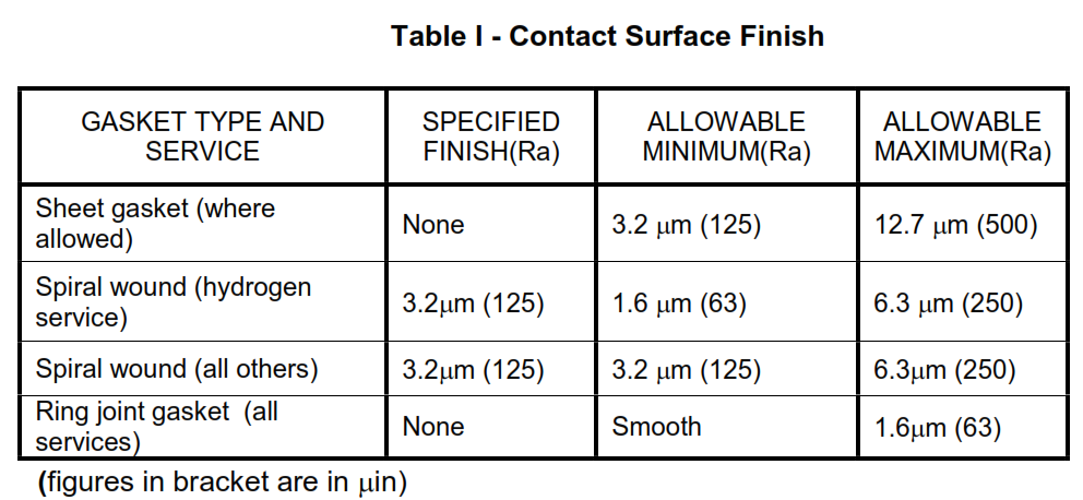
Flanges shall be finished in accordance with MSS SP-6, and ASME B46.1. Table 1 defines
the acceptable ranges of contact surface finishes for each type of gasket and service. The
surface finishes are to be specified in Ra, Roughness average, expressed in micro-meters,
followed by micro-inches. For special services such as Vacuum / oxygen, the contact surface
finish shall be as per Licensor’s requirement.
Table I – Contact Surface Finish
11.1.2 Visual Inspection
Flange roughness shall be judged by visual comparison using GAR model S-22 Micro finish
Comparator or equal. The manufacturer shall use whatever machining methods (nose radius
and feed rate) are required to achieve the specified surface finish.
12 Purchase Description for Gaskets
The following information shall be included in the Purchase Description:
a. Type of Gasket
b. Rating
c. Material
d. Material Grade
e. Nominal size of gasket
f. Centering ring.
g. Inner ring
h. Ring Number
i. Manufacturer, when the gasket is proprietary
j. Dimensional standard.
k. Additional requirements
The above mentioned information are minimum. For the detailed Purchase requirements for gaskets,
refer PIP PNSM0105.