1. GENERAL
……………………………………………………..
1.2
References 4
1.3
Submittals 5
1.4 Quality
Assurance
………………………………………
2. PRODUCTS
2.1 General
2.2 Materials ……………………………………………………2.3
Design
Criteria 8
2.4
Fabrication And Manufacture
2.5
Inspection And Tests …………………………………..
2.6
Identification and Tagging
2.7
Preparation For Shipment
3. EXECUTION
………………………………………………….
4. ATTACHMENTS
TABLE
I. Non Destructive Examination for Body and Bonnet
1. General
1.1 Summary
1.1.1 Scope of Specification
1.1.1.1 This specification prescribes the requirements for purchase of Ball, Butterfly, and Plug valves.
Other types of soft seated valves and quarter-turn metal seated valves shall be in accordance with this
specification as applicable.
1.1.1.2 This specification is a supplement to the Item Description shown in the Bills of Material.
1.1.2 Work Not Included
1.1.2.1 Installation of valves is not included in Supplier’s scope except to the extent of providing installation
instructions as part of the Submittals.
1.1.2.2 Maintenance and repair of material after receipt and acceptance by authorized personnel and
jobsite storage are not included in Supplier’s scope unless warranty repairs are determined to be required.
1.1.3 Related Specification Work in this specification shall be coordinated with the following United Piping
Engineering Specifications, which provide related technical requirements pertinent to this specification:
SES P18-G01 Design Limitations and Applications of Valves (Gate, Globe, Ball and Check)
SES P14-T03 Piping Traceability and Certification
SES P25-G01 Selection of Flanges
Note. Documents listed above should be attached for Supplier’s information.
1.1.4 Supplied by Supplier
1.1.4.1 Supply of Material
a. Supplier’s scope shall include the supply of material as specified in the PO (Purchase Order) and
written clarifications thereto; modifications necessary to meet the requirements of the Item
Description; additional engineering notes in the PO; examination and testing; preparation of the
material for shipment; suitable packaging; and Manufacturer’s warranty.
b. All piping materials shall be clearly marked with country of origin in accordance with applicable
government regulations. In addition, materials shall be produced by manufacturers specifically listed
in the Acceptable Manufacturers List (AML). Any materials deviating from these requirements must
have prior written authorization or shall be subject to rejection or additional verification or testing at
Seller’s expense.
1.1.4.2 Equivalent Manufacturers
Items specified or referenced by Manufacturer and figure number are not intended to exclude equal items
offered by other Manufacturers. Products made by reputable Manufacturers and of comparable type,
quality, and characteristics may be submitted for evaluation.
1.1.4.3 Refurbished Material
Valves furnished shall be original Manufacturer’s production. Reconditioned or new surplus valves shall
not be furnished without prior written authorization.
1.1.4.4 Approved Manufacturer
The approved Manufacturer, shown below the Item Description on the PO, is Manufacturer and figure
number accepted by Contractor; no other valve manufacturer may be furnished other than that shown.
When a manufacturer and figure number is not shown below the Item Description, the supplier shall
furnish the valve manufacturer and figure number referenced in the Item Description.
1.1.5 Terminology
1.1.5.1 Authorized or Authorization: Authorized or authorization given by Contractor Piping Engineering.
1.1.5.2 Major Repairs: Repairs defined as major in ASTM-A217.
1.1.5.3 Minor Repairs: Repairs not defined as major repairs.
1.1.5.4 Critical Areas: Areas for radiographic coverage that shall be a matter of agreement between
Contractor and Manufacturer in accordance with ASME B16.34.
1.1.5.5 Casting Quality Factor: A factor E(c) assigned to the quality of castings defined by ASME B31.3.
1.1.5.6 100 Percent Examination: 100 percent volumetric examination by radiography or 100 percent of
exterior surface examination by dye penetrant or magnetic
particle; these are defined in the PO or Item Description and shall not be required unless so stated.
1.1.5.7 Refurbishment: The furnishing of valves that are not new and not the original Manufacturer’s
production.
1.2 References
The publications listed below form part of this specification. Each publication forming part of this
specification shall be the latest revision and addendum in effect on the date this specification is issued for
construction unless noted otherwise. Except as modified by the requirements specified herein or the details
of the drawings, Work included in this specification shall conform to the applicable provisions of these
publications.
American Petroleum Institute (API)
6D Specification for Pipeline Valves (Steel Gate, Plug, Ball, and Check Valves) 598 Valve Inspection and
Testing
599 Steel and Ductile Iron Plug Valves
607 Fire Test for Soft Seated Quarter-Turn Valves
608 Metal Ball Valves – Flanged and Butt Welding Ends
609 Lug- and Wafer-Type Butterfly Valves
American Society of Mechanical Engineers (ASME)
Boiler and Pressure Vessel Section II Material Specifications
Boiler and Pressure Vessel Section IX Welding and Brazing Qualifications
B1.1 Unified Inch Screw Threads
B1.20.1 Pipe Threads, General Purpose (Inch)
B16.1 Cast Iron Pipe Flanges and Flanged Fittings
B16.5 Pipe Flanges and Flanged Fittings
B16.10 Face-to-Face and End-to-End Dimensions of Valves
B16.11 Forged Steel Fittings, Socket welding, and Threaded
B16.20 Metallic Gaskets for Pipe Flanges – Ring-Joint, Spiral-Wound, and Jacketed
B16.25 Butt Welding Ends
B16.34 Valves – Flanged, Threaded, and Welding End
B16.47 Large Diameter Steel Flanges, NPS 26 through 60
B31.1 Power Piping
B31.3 Process Piping
B31.4 Liquid Transportation Systems for Hydrocarbons, LPG, An hydrous Ammonia, and Alcohols
B36.10M Welded and Seamless Wrought Steel Pipe
B36.19M Stainless Steel Pipe
B46.1 Surface Texture
American Society of Non-Destructive Testing (ASNT)
SNT-TC-1A Recommended Practice for Nondestructive Testing Personnel Qualification and Certification
American Welding Society Standards (AWS)
A5.13 Specification for Solid Surfacing Welding Rods and Electrodes
Manufacturers Standardization Society of the Value and Fittings Industry (MSS)
SP-6 Standard Finishes for Contact Faces of Pipe Flanges and Connecting-End Flanges of Valves and
Fittings
SP-25 Standard Marking System for Valves, Fittings, Flanges, and Unions SP-53 Quality Standard for
Steel Castings and Forgings for Valves, Flanges, Fittings, and Other Piping Components – Magnetic
Particle Examination Method
SP-54 Quality Standard for Steel Castings for Valves, Flanges, Fittings, and Other Piping Components
SP-55 Quality Standard for Steel Casting for Valves, Flanges, Fittings, and Other Piping Component –
Visual Method
SP-61 Pressure Testing of Steel Valves
SP-67 Butterfly Valve
SP-68 High Performance-Offset Seat Butterfly Valves
SP-72 Ball Valves with Flanged or Butt Welding Ends for General Service
SP-78 Cast Iron Plug Valves, Flanges, and Threaded Ends
SP-93 Quality Standard for Steel Castings and Forging for Valves, Flanges, Fittings, and Other Piping
Components – Liquid Penetrant Examination Method
SP-94 Quality Standard for Steel Castings and Forging for Valves, Flanges, Fittings, and Other Piping
Components – Ultrasonic Examination Method
(National Association of Corrosion Engineers) (NACE)
MR-01-75 Sulfide Stress Corrosion Cracking Resistant Metallic Materials for Oilfield Service
1.2.7 Precedence of Requirements
1.2.7.1 Conflicts in technical requirements shall be resolved in the following order of precedence:
a. Technical requirements specified in the RFQ or PO, as applicable, and identified as Additional
Technical Requirements or Engineering Notes.
b. The Item Description as shown on the Bills of Material.
c. The requirements of this specification.
d. The requirements of referenced codes or standards (for example, API Std. 609).
1.3 Submittals
1.3.1 Certificate of Compliance
1.3.1.1 Supplier shall furnish certification of compliance to all requirements of the Purchase Order in
accordance with Supplier Drawing Data (SDR) Report. The certification shall include Contractor’s PO
number, Item Code Numbers, name and address of Supplier, and shall be signed by Supplier’s authorized
agent.
1.3.1.2 The following applies to valves with body and bonnet material specified to an ASME (SA or SB)
specification in the Item Description:
a. Supplier shall furnish Manufacturer’s certification of compliance with the referenced ASME
specification for the body, bonnet and bonnet bolting. The documents shall be identified with
Contractor’s PO Number and Item Code Number and shall be signed by Manufacturer’s authorized
agent.
b. ASTM materials may be substituted for materials specified as ASME, provided that the ASME
pecification is indicated (below the title) to be identical with the corresponding ASTM specification for
the grade, class, or type produced. Manufacturer shall state the dual compliance on the Certification
of Compliance. ASTM specification material substitutions shall be submitted for evaluation at the time
of quotation.
Manufacturer Test Reports (MTRs)
A complete MTR (Manufacturer Test Report) showing results of chemistry and physical tests shall be
provided for impact tested steels, chrome steel, stainless steel, and nickel alloy valves. The MTR shall
include, as a minimum, name of Supplier, name of prime material supplier, item code number, material
specification, grade and class, actual test results of chemical analysis and mechanical properties, and
certified by the Q. A. Manager or authorized representative.
1.3.3 Welding Procedures
If specified in the PO or in the Item Description, and if valves are manufactured with pressure retaining
welds (including seal welds and where castings are repaired by welding), Supplier shall furnish
Manufacturer’s welding procedures, ASME QW-482, and PQR (Procedure Qualifications Record) QW-483
for Contractor Welding Engineering acceptance. The procedures and qualifications shall be in accordance
with ASME Section IX and shall specify the maximum allowable fit-up offset and misalignment for girth and
miter joint butt welds. The qualification shall include hardness testing in accordance with the applicable
Piping Code, i.e. ASME B31.3 or B31.1. The hardness testing shall be performed on the base metal, weld
metal, and the heat affected zone and after any required heat treatment.
1.3.4 Supply of Drawings
1.3.4.1 Dimensional drawings shall be furnished for the following:
a. All valves.
b. Valves for which published catalog dimensional data are not available.
c. Gear operator installations.
d. Valves with nonstandard dimensions.
e. Valves with welded-on nipples.
f. Detail of the end bevel for weld-end valves with nominal wall thickness greater than 0.88 inch (22.2
mm). These drawings need not be certified except when called for in the PO or the Item Description.
1.3.4.2 Supplier shall be prepared to furnish, on request, dimensional drawings showing stem or shaft
sealing design and number of size of packing rings or stem seals required for each type and size of valve in
the PO.
1.3.4.3 Total weight of the valve, including operator, shall be shown on the drawings.
1.3.4.4 Drawings shall include materials of construction with referenced ASTM material specification.
1.3.5 Hydrotest Certification
Supplier shall furnish certification of hydrotest in accordance with Section 2.5.1 of this specification. Test
results may be included in the Manufacturer’s Test Report (MTR).
1.3.6 Maximum Field Pressure Test
Supplier shall furnish the maximum allowable hydrostatic shell and seat test pressures that valves can be
subjected to, during field pressure testing, for valves not manufactured in accordance with a standard.
Note: All submittals (except weld procedures per Item 1.3.3 and drawings per Item 1.3.4) shall be shipped
with the valves. Do not send to Contractor’s office.
1.4 Quality Assurance
1.4.1 Inspection Authorization
Examination or tests may be reviewed or witnessed by Contractor or its authorized agent at Supplier’s or
Manufacturer’s facility.
1.4.1.1 A general inspection of the facility for quality control procedures may be made as selected by
Inspector.
1.4.1.2 Valve castings shall have visual inspection in accordance with MSS SP-55 as selected by
Inspector.
1.4.1.3 Repairs shall be inspected as selected by Inspector after the repairs have been made.
1.4.2 Refurbishment
1.4.2.1 Refurbishment is not permitted unless specifically authorized in writing by Contractor.
1.4.2.2 Modification of new valves is permitted only if specifically authorized, and if the requirements of
Section 2.4.3 are satisfied.
1.4.3 Major Repairs
Major repairs shall not be performed without authorization. Welding procedures may be furnished for
evaluation as an alternative to this requirement.
2. Products
2.1 General
Valves shall be in accordance with the applicable API Standards, except as noted below.
2.2 Materials
2.2.1 Ball Valves
2.2.1.1 Ball valves shall provide a continuous electrical path between ball and body or shall be equipped
with a spring or spring-loaded pin to provide grounding.
2.2.1.2 Reduced port ball valves shall have a bore through the ball no less than that specified in API 6D.
2.2.1.3 Weld end valves with resilient seats shall be designed to allow welding into piping without
disassembly.
2.2.1.4 If unibody or 1-piece body is specified, ball valves shall have no external body joints. If 2-piece
bolted body is specified, ball valves shall have no threaded body joints. If end entry or split body is
specified, either is acceptable. Designs in which the stem seal or packing area is split between 2 of the
body components are not acceptable. Supplier shall certify that body joints, including the stem seals, shall
not leak under the loads of a fully stressed connecting piping system, as defined in the applicable codes.
2.2.1.5 Trunnion mounted ball valves shall have a means of relieving excessive body cavity pressure.
2.2.1.6 Valves specified as block-and-bleed type shall have a tapped opening of at least NPS 1/2 (NPS 3/4
for valves NPS 6 and larger) located in the bottom of lower side of the valve body.
2.2.1.7 Stems shall be of the blowout-proof design.
2.2.2 Butterfly Valves
2.2.2.1 Face-to-face dimensions of rubber-lined and high performance butterfly valves shall comply with
API 609.
2.2.2.2 Butterfly valves shall be bi-directional and provide equal shutoff in either flow direction to the full
pressure rating of the valve.
2.2.2.3 Lug type butterfly valves shall hold full rated pressure in either flow direction with the mating flange
disconnected.
2.2.2.4 Valve gasket seating surface area shall not contain any disruptions (screw holes or retainer edge)
within the effective sealing area of an ASME B16.20 spiral wound gasket.
2.2.2.5 Disc shall stay in the closed position against full rated pressure in either flow direction if the
operator becomes disconnected from the shaft.
2.2.3 Lubricated Plug Valves
2.2.3.1 Cast iron valves shall comply with MSS SP-78. Ductile iron, carbon steel, stainless steel, and
nickel alloy valves shall comply with API 599.
2.2.3.2 Valves shall be furnished with lubricant suitable for 230 degrees C operation.
2.2.4 Sleeved Plug Valves
Valves shall comply with API 599 except that stainless steel and nickel alloy valves may
have wall thickness in accordance with ASME B16.34.
2.2.5 Brass and Bronze Valves
2.2.5.1 Brass and bronze valves shall be Manufacturer’s standard.
2.2.5.2 Materials of construction shall be Manufacturer’s standard except asbestos
materials are not permitted.
2.2.6 Cast Iron and Ductile Iron Valves
2.2.6.1 Cast iron and ductile iron butterfly valves shall comply with API 609. Ductile iron flanged plug valves
shall comply with API 599.
2.2.6.2 Materials of construction shall be Manufacturer’s standard except asbestos materials are not
permitted.
2.2.7 Cast or Forged Steel, Low Alloy, Stainless and High Nickel Alloy Valves
2.2.7.1 Design
Ball valves shall comply with API 608. Rubber lined and high-performance butterfly valves shall comply
with API 609. Lubricated plug valves and sleeved nonlubricated plug valves shall comply with API 599.
Ball, butterfly, and plug valves specified in the Item Description as fire safe or fire tested shall comply
with applicable requirements of API 607. Fire safe plug valves may not contain vent holes in the side of the
plug and shall be capable of bi-directional shutoff.
2.2.7.2 Trim
The base material of balls, discs, and plugs shall be of the same material (or higher alloy) than the body. If
carbon steel or electroless nickel coated trim is specified, 316 stainless steel may be provided. Hardfacing,
if specified, shall be of Number 6 composition or equivalent, according to AWS A5.13 grade CoCrA.
ASTM-A564, grade 630 (17-4PH stainless steel) used for stems shall be heat treated in accordance with
NACE MR-01-75, Appendix A, and shall have a hardness within the range of HRC 29 to HRC 33.
2.2.7.3 Stem Seals
Stem seals shall be a graphited, braided, nonasbestos packing suitable for 538 degrees C steam or
petroleum services and shall contain a sacrificial metal corrosion inhibitor, or pure graphite foil packing
suitable for 538 degrees C oxidizing services with braided graphite fiber rings on the top and bottom of the
packing stack. Where TFE [Teflon (polytetra-fluorethylene)] packing is specified in the Item Description, it
may be either braided nonasbestos packing impregnated with TFE, braided pure TFE packing, or pure
virgin TFE chevron rings. Graphite is not permitted in TFE packing.
2.2.7.4 Bonnet Gaskets
For valves specified in the Item Description as fire safe or fire tested, gaskets shall be graphite or spiral
wound metal with filler. Metal windings shall be type 304 stainless minimum, and filler shall be nonasbestos
suitable for 427 degrees C or graphite, unless otherwise stated in the Purchase Description.
2.2.7.5 Bonnet Bolting
Bolting shall be ASTM-A193 grade B7 with ASTM-A194 grade 2H nuts unless otherwise specified in the
Item Description. If sour service or H2S service is specified in the description, bolting shall be according to
NACE MR-01-75 Class II. Bolt protrusion through the nut shall be 1-1
/2 threads maximum.
2.2.7.6 Metallurgy
a. Austenitic stainless steels shall be furnished in the solution annealed condition.
b. Monel body material for screwed, socketweld end, and butt weld end valves shall be of a weldable
composition.
2.3 Design Criteria
2.3.1 Dimensions
Valves shall have an End-to-End dimension in accordance with standards referenced for manufacture.
End-to-End dimensions of flanged end, butt weld end, or wafer type valves that differ from Manufacturer
and figure number listed in the Purchase Description (such as short pattern versus regular pattern) are not
permitted without authorization.
2.3.2 Sour Service or H2S Service
Materials furnished for valves where the Item Description states for sour service or for H2S service shall be
in accordance with NACE MR-01-75.
2.3.3 No Copper
Valves specified in the Item Description as “no copper permitted” shall not have copper or copper bearing
alloy (except trace amount) materials used in their construction. This includes internal and external parts
such as trim, grounding spring, stem bearings, and gland follower.
2.3.4 Welded-on Flanges
Flanged end valves with welded-on flanges, if they would result in a nonstandard length, are not permitted.
Butt weld ends machined from flanged valves are not permitted.
2.3.5 End Bores
Weld bevels and end preparation shall be in accordance with ASME B16.25.
2.3.6 Threaded and Socketweld Ends
Threaded ends shall have taper pipe threads in accordance with ASME B1.20.1. Socketweld ends shall be
in accordance with ASME B16.11.
2.3.7 Flange Finish
The finish for gasket surfaces of flanged ends shall be in accordance with ASME B16.5. The gasket
surface shall have concentric or spiral grooves resulting in a roughness height within the range of 125 to
250 microinch Ra. Roughness heights outside of this range are not permitted. Acceptance criteria for
flange damage are listed in SES P25-G01.
2.3.8 Back Seat
Not applicable.
2.3.9 Body Tappings
Location and designation of body tappings, if so specified in the Item Description, shall be in accordance
with Figure 1 of ASME B16.34. Tappings shall be taper pipe threads in accordance with ASME B1.20.1
and shall be fitted with solid forged plugs of the same basic metallurgy as the valve body. Socket welding
openings shall be in accordance with ASME B16.11 and shall be fitted with plastic plugs.
2.3.10 Floating or Trunnion Ball
Ball valves specified as floating ball may be furnished as trunnion mounted ball. Ball valves specified as
trunnion mounted may be furnished as floating ball only with authorization.
2.3.11 Operators
2.3.11.1 Lever operated valves shall be furnished with individual levers, wrenches, or handles.
2.3.11.2 Gear operators shall be fully enclosed type with cast housing, furnished with a position indicator.
Designs capable of being misassembled such that the position indicator could indicate an orientation
different from the valve internals are not permitted. Enclosures fabricated from sheet metal are not
permitted.
2.3.12 Tapped Bolt Holes
Tapped bolt holes in valve bodies, such as in lug type or single flange valves, shall be threaded in
accordance with ASME B1.1. Threads shall be the Coarse Thread Series (UNC) through 1-inch bolt size
and the 8 Pitch Thread Series (8UN) for bolt sizes of 1-1/8 inch and larger, with a Class 2B tolerance.
2.4 Fabrication And Manufacture
2.4.1 Fabrication by Welding
Valves fabricated entirely or partially by welding, not including seal welds of bonnets, shall comply with the
design requirements of this specification unless specifically authorized by Contractor. Welding procedures are required for evaluation prior to commencement of fabrication. All welding shall be carried out only by
qualifiedwelders. Welding is not allowed for pressure components of cast iron material
2.4.2 Repairs
Minor casting repairs shall conform to the ASTM specification referenced for manufacture. Limitations on
imperfections and method and extent of required examination for repairs shall be the same as required for
the original castings. Repair of castings by peening or impregnation with metallic or nonmetallic materials is
prohibited.
2.4.3 Modification of New Valves
2.4.3.1 Modifications are not permitted without authorization.
2.4.3.2 Modifications to valves that have been completely assembled and pressure tested by Manufacturer
shall conform to one of the following, as applicable:
Modifications by Manufacturer
a. If modifications have been performed by Manufacturer of the valve, the completely modified valve
shall be pressure tested in accordance with Section 2.5.1.
b. Modifications by Other than Manufacturer
c. Modifications shall be described in the quotation and shall contain the information listed below:
(i) Extent of modification (packing change, new seat material, refacing of flange faces).
(ii) Name of the firm performing modification.
(iii) Statement of warranty.
2.5 Inspection And Tests
2.5.1 Pressure Testing
2.5.1.1 Valves shall be pressure tested in accordance with the standard to which they are manufactured.
Valves manufactured to an API standard shall be tested to API 598. Steel valves not covered by an API
standard shall be tested in accordance with MSS SP-61. Other valves shall be tested in accordance with
the procedures of MSS SP-61 except that the test pressures shall be as follows:
a. Shell: 1.5 × P
b. Seat: 1.0 × P
where P is the nonshock cold working pressure or WOG (Water-Oil-Gas) rating specified by Manufacturer.
2.5.1.2 Pressure testing of austenitic stainless steel valves shall conform to the following additional
requirements:
a. Only water containing fewer than 50 ppm (.050 mg/liter) chloride ion shall be used for pressure
testing.
b. Following pressure testing, the test water shall be immediately drained and valves shall be dried by
blowing with air or dry nitrogen.
c. The type or style of valve stem packing or stem seals used during pressure testing shall be the
same as that specified to be supplied with the valve.
d. Valves packed for vacuum (external pressure) service shall be allowed the same leak rate as
defined for internal pressure.
2.5.2 Examination
2.5.2.1 Examination is required only where specified in the Item Description or the Purchase Order.
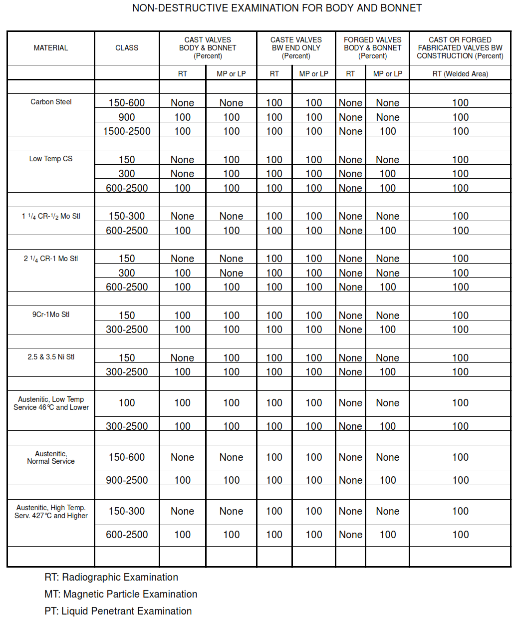
Non-destructive examination shall be per Table 1.
TABLE I
NON-DESTRUCTIVE EXAMINATION FOR BODY AND BONNET
1.1.1.2 Surfaces to be examined shall be clean and free from surface conditions that may mask
unacceptable conditions. Surface of casting shall be cleaned by
sandblasting, shotblasting, acid pickling or Seller’s standard treatment materials.
1.1.1.3 Personnel performing or evaluating examinations, other than visual examination and hardness
testing, shall be qualified in accordance with the ASNT Recommended Practice SNT-TC-1A. Only Level II
or III personnel shall be authorized to interpret results for radiographic and ultrasonic examinations.
a. Valve castings shall meet the visual acceptance standards of MSS SP-55.
(i) The visual inspection of castings shall be performed using the Reference Photographs in MSS
SP-55.
(ii) Machined surfaces shall be free of injurious dent, burr and unevenness in finished conditions. The
seating surfaces shall be free of blow holes and cracks. Appropriate chamfer or rounding shall be
provided to corners and edges for which no dimensions are specified. Fluid passage section shall be
cleaned and prepared with utmost care.
b. If radiographic examination is specified or performed, examination and acceptance criteria shall
follow MSS SP-54. If casting quality factor of 1.00 is specified in the Item Description, the additional
requirements of Paragraph 2.5.3 shall apply.
c. If magnetic particle examination is specified or performed, examination and acceptance criteria
shall follow MSS SP-53.
(i) If magnetic particle examination has been specified, liquid penetrant examination may be applied
only to surfaces not accessible for magnetic particle examination.
(ii) If casting quality factor of 1.00 is specified in the Item Description, the additional requirements of
Paragraph 2.5.3 shall apply.
d. If liquid penetrant examination is specified or performed, examination and acceptance criteria shall
follow MSS SP-93.
If casting quality factor of 1.00 is specified in the Item Description, the additional requirements of
Paragraph 2.5.3 shall apply.
e. If ultrasonic examination is specified or performed, examination and acceptance criteria shall follow
MSS SP-94.
f. Impact tests, if required by the material specification or if required by the Item Description, shall be in
accordance with the applicable Piping Code, i.e. ASME B31.1, ASME B31.3, ASME B31.4, etc.
1.1.3 Additional Examination Requirements
Wherever Casting Quality Factor of 1.00, Critical Service, or Category M Service is specified in the Item
Description or the Purchase Order, castings in all materials shall have a casting quality factor E(C) of 1.00
according to ASME B31.3, Chapter II -” Increased Casting Quality Factor E” Table consisting of either
2.5.3.1 or 2.5.3.2, following:
1.1.3.1 Carbon Steel and Chrome-moly Alloy
a. All accessible exterior and interior surfaces of each casting in carbon steel and chrome-moly alloy
materials shall have dry powder magnetic particle examination in accordance with MSS SP-53 with
acceptance criteria in accordance with MSS SP-53, using reference photographs in ASTM-E125.
b. Fully radiograph all critical areas as defined by the manufacturer and agreed upon by Contractor
Piping Materials Engineer. Radiography shall be in accordance with MSS SP-54 with acceptance
criteria in accordance with ASME/ B31.3, Chapter II – “Acceptance Levels For Castings” Table and
reference radiographs in ASTM-E446, E186, or E280 as applicable.
1.1.3.2 Austenitic Stainless Steel and Nickel Alloys
a. All accessible exterior and interior surfaces of each casting in austenitic stainless steel or nickel
alloy castings shall have liquid dye penetrant examination in accordance with ASTM-E165 with acceptance criteria in accordance with Table 1 of MSS SP-53, using ASTM-E125 as a reference for
surface flaws.
b. Fully radiograph all critical areas as defined by the manufacturer and agreed upon by Contractor
Piping Materials Engineer. Radiography shall be in accordance with MSS SP-54 with acceptance
criteria in accordance with ASME/ B31.3, Chapter II – “Acceptance Levels For Castings” Table and
reference radiographs in ASTM-E446, E186, or E280 as applicable.
1.1.4 Dimensional Measurement
One valve shall be measured by sampling per ten valves (minimum one valve) for each kind. Here, each
kind means that the type, material, pressure rating and dimensions are the same. Dimensions of joint ends
such as flange, welding joint and screw end shall be observed to meet the pertinent standard pecifications.
Tolerances of center-to-face dimension of flanged or butt welding end valves shall be in accordance with
para. 6.0 of ASME B16.10.
1.1.5 Operation Test
By operation of the handle (handwheel or gear handle), it shall be observed that the opening and closing
operations of the valve are carried out smoothly. When the handle (hand wheel or gear handle) is turned
clockwise, the valve shall be closed. When the valve is fully closed or opened, no galling or sticking shall
be observed in each moving part. Operation test is required for each valve.
1.1.6 Alloy Verification Examination
Applicable parts: Valve body, valve bonnet, end-flange if welded into valve body. This examination shall be
performed by the valve manufacturer only when specifically required by the valve order Requisition,
Specification or Data sheets. When not performed by the manufacturer, the alloy verification will be
performed at the site. Materials found to be not as specified or incorrectly identified shall be subject to
rejection
1.1.7 Steam Test
If specified in the individual specification, the valve shall be heated up for at least one hour with steam
available in shop facility. After cool down, valve seat leakage test to API 598 and operation test shall again
be applied. One test shall be performed per size, type, rating and material.
1.1.8 Dismantling Inspection
Valves shall be dismantled with sampling one out of same specification valves (i.e. each valve type, each
material, each size and each rating) following operation and pressure test and shall be observed to see if
internal components such as stem, seat ring, disc and bonnet gasket have the specified materials and that
there are no harmful defects inside the valves. After this inspection the dismantled parts shall be
appropriately re-assembled.
2.6 Identification and Tagging
2.6.1 Marking
Each valve shall be marked in strict accordance with the standards referenced for manufacture. The
minimum requirements of MSS-SP-25 shall be satisfied.
2.6.2 Tagging
2.6.2.1 Each valve shall be fitted with a rust resistant metal tag securely attached with no fewer than 6
twists of stainless steel wire. Paper or plastic tags are unacceptable.
2.6.2.2 Tags shall normally be attached to the gland bolting. Tags on valves that do not have gland bolting
may be attached to the handwheel or other appropriate location. Attachment of tags through bolt holes of
end flanges is not permitted.
2.6.2.3 Each tag shall be clearly stamped with the Item Code Number and the PO Number. Ink or paint is
not acceptable for marking. The Item Code Number is the number appearing directly above the first line of
each Item Description on the Bills of Material.
2.6.2.4 Where the Item Description specifies that the valve is for a specific service, Supplier shall attach an
additional tag spelling out this requirement.
Example: FOR CHLORINE SERVICE
2.6.2.5 The minimum dimensions for tags and wire shall be in accordance with the following:
a. Size of tag:
(i) Round 1-
/2 inch (40 mm) diameter
(ii) Rectangular
1
/4 inches (12 by 70 mm)
b. Thickness of tag: 16 B&S Gage 0.051 inch (1.2 mm) minimum
c. Lettering height:
1
/2 of an inch by 2-
3
/4 of an inch (6 mm) minimum
d. Wire diameter: 16 B&S Gage 0.051 inch (1.2 mm) minimum Proper tagging is essential in the
Contractor material management system. Supplier must comply with this requirement.
1
2.7 Preparation For Shipment
2.7.1 Ball and plug valves shall be in the open position for shipment. Butterfly valves shall be in the closed
position for shipment.
2.7.2 Valves shall be shipped with the correct stem packing installed and with the gland follower ufficiently
tightened to prevent loss of packing gland bolting during shipment.
2.7.3 Valves shall be prepared in such a manner as to avoid damage or atmospheric corrosion to inside or
outside surfaces or parts during storage or while in transit. Use API 600 as a minimum standard of
cceptance.
2.7.4 Unmachined exterior surfaces of the shell of ferritic valves shall be painted. Austenitic stainless steel
valves shall not be painted.
2.7.5 Austenitic stainless steel valves shall be protected from chlorine attack such as might occur from
exposure to saltwater spray or atmosphere during shipment, cleaning, fabrication, testing, and storage.
Protection shall also be provided if shipping by truck in areas where road salt is used. Consideration shall
be given to enclosing or wrapping in a vaporproof barrier material.
2.7.6 Unless export packaging is specified, valves may be shipped loose or packed in a box or crate.
2.7.7 If export packaging is specified, valves shall be shipped in wooden boxes or crates, individually or
collectively, in a manner to prevent shifting within the container.
2.7.8 Threaded and socket-welding openings shall be closed with plastic or metal protectors to exclude dirt
and other foreign matter from the interior of the valves.
2.7.9 Flange facings and butt welding ends shall be protected over the entire gasket seating surface or
weld end with high-impact plastic covers and secured with lock plugs (integral or separate) or steel
strapping. Plastic end protectors of at least
1/2 of an inch (12 mm) thickness, secured with at least 4 bolts or
with steel strapping, are also acceptable. Cardboard or pressboard end protectors are not acceptable.
2.7.10 Carbon steel and ferritic alloy steel flanged and butt weld end valves shall have end flange facing
and bevels coated with a peelable or solvent-removable rust preventative coating before the end protectors
are applied.