1. SCOPE
………………………………………………………………………….
2. REFERENCES
3. DEFINITIONS
4. GENERAL
………………………………………………………………………
4.1
Plant Drainage and Sewer Systems
4.2
System Description
5. DESIGN CONSIDERATIONS ……………………………………………5.1
System Design Principles
5.2 Design Basis
5.3
Pipe Sizing ………………………………………………………………..
5.4
Ditch Sizing
5.5 Impoundment
Sizing
5.6
Infiltration …………………………………………………………………..
5.7
Tie-Ins to Existing Systems
6. DRAINAGE AND SEWER SYSTEM COMPONENTS
6.1 Drainage
Area
Layout
………………………………………………..
6.2
Drains 15
6.3
Catch Basins
6.4 Manholes
………………………………………………………………….
6.5
Lift Stations (Pumping Stations)
6.6
Fire Seals
6.7 Cleanouts
…………………………………………………………………
6.8 Vents
6.9 Drainage
Ditches
7. SAFETY
…………………………………………………………………………
7.1 Existing
documentation
7.2
Excavation and trenching
8. MATERIALS SELECTION ………………………………………………..8.1 General
8.2
Piping Materials
9. INSTALLATION
……………………………………………………………….
9.1 General
9.2 Cover
9.3
Line Protection …………………………………………………………..
9.4 Laying
Pipe
9.5
Jointing and Finishing
9.6
Culverts …………………………………………………………………….
FIGURE
1. Nomograph for Determination of Overland Flow Time
2.
Rainfall Intensity – Duration Curve
3.
Equipment and Process Area Drainage Arrangement ………….
4.
Fire Seal Configuration – Offsite Sewers or Main Sewer Lines
5.
Sewer System Details
1. Scope
1.1 This Specification covers the basic requirements for the design, selection of materials, installation, and
testing of open stormwater and wastewater sewer systems. This Specification does not apply to
chemical-resistant drains and sewer systems.
1.2 Closed process drains and collection systems for oils and specialty waste streams shall be regarded as
process plant pipework and shall be designed in accordance with Specifications P01 E01 (Design
Conditions and Design Basis for Pressure Piping) and P01 E09 (Piping Layout, Spacing, and Clearances.)
2. References
The Project Specifications listed below form part of this specification. Each specification shall be the latest
revision and addendum in effect on the date this specification is issued for construction unless noted
otherwise.
SABIC Engineering Standards
P01 E01 Design Conditions and Design Basis for Pressure Piping
P01 E09 Piping Lay-out, Spacing and Clearances
P01 E14 Requirements of Pipeline Crossing Under Roads and Pavements
P01 E21 Fire Water System Layout and Design
P01 E28 Design Requirements for FRP Piping Systems
P01 E36 Design of Plumbing Piping Systems
P12 S04 Color Coding Criterion
P13 C01 Construction, Installation and Back filling Procedures
P13 C02 Field Fabrication and Erection
P13 C05 Construction requirements for FRP Piping Systems
P14 T01 Inspection requirements and Procedures per API 570
P14 T02 Quality Assurance of FRP Piping
P04 S01 Piping Material Standard Specification Part III
3. Definitions
Catch Basin. An open device used at a single point to collect surface drainage with an outlet liquid seal
and sediment trap.
Combined Sewer. Common sewer system collecting both wastewater and stormwater.
Contact Stormwater. Stormwater that has come into contact with any raw material, intermediate product,
finished product, byproduct, or waste product. Contact stormwater is likely to contain petroleum
hydrocarbons and should be considered contaminated.
Cleanout. A piping connection in a sewer system that is located at grade level for inspecting and/or
cleaning the system.
Closed Sewer Systems. A drainage and sewer system that is equipped with a closed vent system and not
open to the atmosphere.
Drain Hub (also called bell or tundish) . An open pipe connection located above grade level to collect
drips or discharges from pump bases, piping, sample draw-off points, and equipment drains. Sublaterals
connect drain hubs to sealed connections in manholes.
Drainage Area (also called catchment and watershed areas) .The area served by a sewer system
receiving stormwater.
Ditch (also called trench). A two or three sided trough located in the ground.
Dry Box . Dry boxes are located at the low point of drainage areas containing fired equipment.
Invert Elevation. The elevation of the inside bottom of the sewer line.
Laterals. Drain lines collecting wastewater from two or more sublaterals and discharging into a sewer
main.
Lift Station. An underground structure (e.g., a sump) with a pump used to pump wastewater to a higher
elevation.
Oily Water. Wastewater generated during the industrial process that contains oil, emulsified oil, or other
hydrocarbons.
Open Gravity Systems. Sloped piping network and auxiliary equipment used to collect liquids received in
catch basins and drains.
Manholes (also called Junction Boxes).An access or collection point in a sewer system line.
Noncontact Stormwater. Stormwater that has not come into contact with any raw material, intermediate
product, finished product, byproduct, or waste product. Noncontact stormwater should not contain
petroleum hydrocarbons and should not be contaminated.
Noncontact Cooling Water . Cooling water which does not come into contact with hydrocarbons or oily
water and which is not recirculated through a cooling tower.
Rainfall Intensity.The amount of rainfall per unit of time [for example, mm/h].
Return Period. The average time interval between the occurrence of an event of a stated magnitude and
an equal or more serious event.
Sanitary Sewage. Wastewater from domestic sanitary sources.
Seals. A device used to isolate the potential spread of fire from one area of a plant to another within a
sewer system.
Sewer Main. A system of primary drain lines that collects wastewater from sublaterals and laterals and
conveys it to a point of treatment/discharge.
Stormwater. Consists of rainwater runoff and non-hazardous drainage.
Sublaterals (also called branches). Lines collecting drains and catch basins that tie into laterals or sewer
mains.
Sumps. An open or covered basin that serves as a collection point for wastewaters.
Time of Concentration (TOC) . The time required for a raindrop to flow from the most remote point of the
drainage area to the so-called design point in a sewer. TOC consists of two components _ The time
required to flow overland to the inlet to the sewer and the time of flow in the sewer to the point under
consideration. The point under consideration is the design point, that is, the sewer line exiting a certain
manhole or catch basin.
Wastewater. Drainage that contains oily water, other hydrocarbons, contact stormwater, or hazardous
chemicals.
4. General
4.1 Plant Drainage and Sewer Systems
All plant stormwater and wastewater drainage systems shall be designed to meet this specification. Items
to be considered in the design include the following: incompatibility of wastewaters, wastewater volumes
and flows, fire protection and loss prevention, area topography, depth of excavation, pumping
requirements, and final disposition. The basis of design for all drainage and sewer projects shall be well
documented for local authority review. Items to be considered in the system design include segregation of
wastes, oil recovery, sludge disposal, chemical wastes, and other disposal problems.
4.2 System Description
Stormwater and wastewater sewer systems shall be designed to be free flowing, to collect and convey all
wastewaters to their final disposition, and to prevent fire hazards from spreading from one area to another.
Different types of wastewaters should be segregated in order to reduce the size, complexity, and costs of
any treatment facility which must be required for managing these wastewaters before final discharge from
the site.
Stormwater and wastewater sewer systems may include the following separate systems, as required.
4.2.1 Stormwater Sewers
Discharges to these systems include noncontact stormwater, noncontact cooling water
(where permitted by the regulations), roadways and access area drainage, parking lot and roof drainage,
and possibly firewater. Diked tank farm areas that have accumulated stormwater are routed to a clean
water sewer unless they are contaminated by spilled material. This system is composed of area drains,
catch basins, ditches, and piping. The treatment and disposition of clean water must conform to Royal
Commission Environmental Regulations.
4.2.2 Wastewater Sewers
Discharges to these systems include contact stormwater, washdown water, tank water drawoffs, pump
gland cooling water in hydrocarbon service, equipment drips and drains, drawoffs from sample
connections, instruments, drain cocks and similar equipment fittings, laboratories, other routinely
contaminated wastewater streams, and possibly firewater. This system is composed of drain hubs, catch
basins, sumps, lift stations, manholes, and piping. Wastewaters are collected in sewer mains and conveyed
to a central treatment facility.
5. Design Considerations
5.1 System Design Principles
5.1.1 Stormwater and wastewater sewer systems shall be able to convey the volumes of wastewater, dike
drainage, stormwater, and firewater that are expected during the operation of the facility. The quality of
each stream shall be determined, and each stream shall be segregated.
5.1.2 Wastewater sewer systems receiving wastewater only shall be sized based on the maximum design
flowrate.
5.1.3 For wastewater sewer systems receiving wastewater, stormwater, and firewater, the size of the
wastewater sewers shall be based upon the maximum flow of wastewater plus stormwater, or the maximum
flow of wastewater plus firewater, whichever quantity is greater.
5.1.4 Sewer systems shall not be designed to operate in flood conditions. Stormwater and wastewater
sewer systems shall be designed to operate principally by gravity. Pipes shall be at levels and gradients
that ensure liquids are not retained in any part of the drain system other than in various traps.
5.1.5 Allowances shall be made for future expansion in sewer designs where expansions can be foreseen
and justified.
5.1.6 Engineer shall examine and evaluate tie-ins to existing plant or other new systems to determine
extent of modifications required.
5.2 Design Basis
5.2.1 Stormwater Flow
5.2.1.1 Method _ The method used in the design of stormwater sewer systems is commonly referred to as
the Rational Method. This method should be limited to areas less than 81 hectares. The Rational Formula
used to determine the design flow is as follows:
Q = 0.00278 CiA (SI units)
Where Q = The peak flowrate at the particular point in the sewer under consideration, m3/s
C = The runoff coefficient for the drainage area. This coefficient is the ratio of the amount of
runoff flowing from the drainage area to the total amount of rainfall that falls on the
drainage area, dimensionless.
Q = 0.00278 CiA (SI units)
Where Q = The peak flowrate at the particular point in the sewer under consideration, m
3/s
i = The design rainfall intensity for the calculated time of concentration, mm/h
A = The size of the drainage area contributing runoff to the sewer, hectares.
5.2.1.2 Design Rainfall Intensity _ A typical storm is characterized by an initial rapid increase in rainfall
intensity, followed by a gradual reduction. When the intensity is at its highest, only areas immediately
adjacent to the sewer contribute flow to the sewer. As the storm continues, more areas contribute tothe
flow, but at a reduced intensity. To account for this phenomenon, the concept of “time of concentration”
(TOC) is used in conjunction with historical rainfall intensity data to develop the design rainfall intensity.
TOC shall be estimated by calculating the time required to flow overland to the inlet to the sewer and the
time of flow in the sewer to end design point. Overland flow time should be determined by using Seelye’s
nomograph (see Figure 1). Sewer flow time should be determined by using the Manning formula in
Paragraph 5.3.1. If sewer data is not available, sewer flow time should be calculated using a sewer velocity
of 1.5 m/s. TOC is equal to the inlet concentration time from Figure 1 plus the time in the sewer to the end
design point. The TOC value should not be less than 10 minutes for developed areas and 20 minutes for
undeveloped areas. These values should be used as default values if the calculated TOC value is smaller.
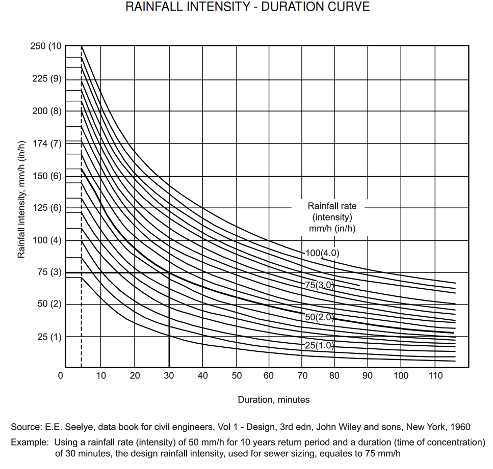
5.2.1.3 Designs shall be based on the rainfall intensity for the length of time required to reach maximum
flow at the point under consideration (15 min). Historical rainfall intensity data can be obtained from
Specification P01 E01.
5.2.1.4 Once this historical rainfall rate (intensity) for a given return period is chosen, Seelye’s
ntensity-duration curve (see Figure 2) can be used to find the appropriate design rainfall intensity for a
corresponding duration based on the time of concentration.
5.2.1.5 For major projects in areas where unusually heavy rainfalls occur, site-specific meteorological data
should be obtained so that the storm sewer system is designed to convey the optimum flow of stromwater
that might occur. In determining this flow, the risks associated with flooding various plant areas should be
weighed accordingly in order to establish a reasonable basis for a design storm
FIGURE 1
NOMOGRAPH FOR DETERMINATION OF OVERLAND FLOW TIME
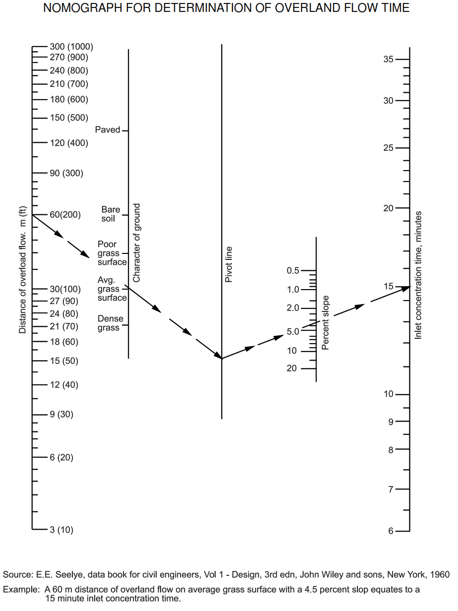
FIGURE 2
RAINFALL INTENSITY – DURATION CURVE
5.2.1.6 Runoff Coefficient – Runoff coefficients vary from 0.3 to 0.95, depending upon the following factors:
slope and irregularity of the drainage area, type and permeability of the drainage area soils or materials of
construction, degree of soil saturation, and type and extent of vegetation present in the drainage area.
Typical values for runoff coefficients are listed below:
Asphalt or concrete paving, roofs 0.90
Macadamized (sprayed) roadways 0.70
Stone 0.40
Bare offsite areas or tank farm:
Clay soils 0.70
Sandy soils 0.60
Grassy areas:
Clay Soils
0.50
Sandy soils 0.30
Compacted Crushed Stone or Gravel Surface 0.70
Uncompacted Gravel Surface Area 0.50
Future plot plan developments that increase the amount of paved area should be accounted for in the initial
design.
5.2.1.7 Computations -Computations should be set up in tabular form with values of drainage areas, unoff
coefficients, overland and sewer TOCs, and design rainfall intensity shown for each area. Care should be
taken to ensure that the correct combination of areas is chosen to yield the maximum flow at the time of
concentration.
5.2.1.8 Detention -Any detention method that will reduce the flowrate into the sewer system will reduce
sewer size. Runoff discharge into sewers can be reduced by impounding the runoff in tank arms,
mpoundments, or tanks.
For steeply sloping offsite areas, terracing can be used to increase overland flow time.
5.2.2 Firewater Flow
The flow of firewater for each process unit drainage system shall take into account the fixed water spray
system and fixed monitor protection. Firewater requirements are stated in Project Specification 00-F-0001.
Firewater flow is assumed to occur only on one process unit at a time. The design firewater flowrate within
the drainage area to a catch basin shall not exceed 115 m3/h.
5.2.3 Wastewater Flow
5.2.3.1 The design wastewater flow should include all continuous and intermittent (once a day or less)
process flows. These flows shall be based on maximum design flow and must assume all intermittent
process flows occurring at the same time.
5.2.3.2 Hydrostatic test water and turnaround drainage should not be included in the design flow calculation
for sizing process sewers. Exceptions to this rule are large process vessels or tanks, which shall be sized to
empty the vessel filled with hydrostatic test water within an eight-hour maximum period. Hydrostatic test
water and turnaround release rate shall be controlled within the hydraulic capacity of the sewer and
wastewater treating system.
5.2.4 Tank Dike Flow
In tank farms, runoff from diked areas is normally impounded therein because the diked area outlet valve is
normally closed. The valve is opened after a storm has subsided or as water level in the diked area
dictates. The design flow of the tank dike drainage system should be based on the greater of (1) drainage
of all accumulated rainwater within the dike in less than 4 hours, or (2) continuous drainage of firewater
without submerging the tank base.
5.2.5 Loading Rack Flow
Loading rack drainage systems shall be designed to drain a hydrocarbon spill quickly from the loading area
into a remotely located wastewater collection and recovery system. Sizing of spill drains at tank car or tank
truck loading racks shall be based on a maximum flowrate from one product arm over a period of several
minutes. This time period, based on the length of time required to shut off the flow from another location,
shall be determined for each installation. In order to minimize wastewater collection and storage, a canopy
or roof should be installed to minimize rainwater collection.
5.3 Pipe Sizing
5.3.1 Method
5.3.1.1 To determine the size of sewers required, the Manning experimental formula and the continuity
equation shall be used as follows:

5.3.1.2 Other recognized formulas require Owner’s approval.
5.3.1.3 Sewers shall be sized to run at 70 percent depth of flow in pipe (i.e., depth of
flow/inside diameter) at design flow. This safety factor provides additional capacity for instantaneous flow
surges and allowances for silt accumulation. The 70 percent depth of flow in pipe shall be calculated by
dividing the design flowrate by 0.837. This new flowrate value is then used in the Manning formula to size
the sewer at flowing full conditions.
5.3.1.4 This depth of flow in pipe requirement may be relaxed with Owner’s approval.
The risks associated with area flooding and surcharging the sewer lines in question should be assessed to
determine if these risks are acceptable. Areas subject to review include large sewer mains, end of sewer
collection system at tie-in to wastewater treatment plant, and sewer laterals and mains draining into a lift
station.
5.3.1.5 For use in the Manning formula, the following hydraulic characteristics of circular pipe shall be used:
HYDRAULIC CHARACTERISTICS OF A CIRCULAR PIPE

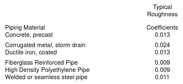
5.3.2 Roughness Coefficients
Roughness coefficients for pipes vary considerably. They depend on the type and condition of sewer
surface material in contact with the flow, as well as on the depth of flow. For use in the Manning formula,
roughness coefficients shall be as follows:
5.3.3 Minimum Line Sizes
The minimum line size for any single sublateral is NPS 4 (NPS = nominal pipe size, inches) for ease of
cleaning. For any lateral sewer containing flow from two or more sublaterals, the minimum line size is NPS
6 for ease of cleaning. The minimum line size for sewer mains is NPS 8 for ease of cleaning.
5.3.4 Velocities
5.3.4.1 Sewers shall be sized to operate within its minimum self-cleansing and its maximum velocities at
design flows. The available slope should be the determining factor in selecting pipe size. If grades will
permit, the maximum velocity should govern. Maximum velocities shall not exceed 2.1 m/s. The following
are acceptable minimum self-cleansing velocities.
Condition Minimum Velocity m/s
General, such as stormwater, and Wastewater 0.9
Moderate amounts of sand or other 0.9
particles present (for example, from
unpaved areas)
Heavy amounts of sand or other particles Present 1.2
5.3.4.2 For sewers in flat areas where minimum velocities cannot be achieved, provision should be made to
clean out settled solids during dry weather periods.
5.3.5 Head Losses
Head losses through culverts and at all entrances, exits, and bends shall be included in system head loss
calculations. These losses will be dependent upon the detail design using standard industry values. Friction
head loss at manholes or catch basins shall be less than 0.03 m for each. In certain cases, the hydraulic
profile should be plotted to determine if a backwater, drawdown, or hydraulic jump condition will result.
5.4 Ditch Sizing
5.4.1 The Manning Formula shall be used for the determination of ditch size. Drainage ditch size shall be
calculated on the basis of flowing full plus 150 mm of free board.
5.4.2 The minimum slope of the ditch shall not be less than .001 m/m.
5.4.3 In order to minimize excessive erosion, maximum velocities shall be limited to 0.6 m/s for unlined
earthen ditches and 1.2 m/s for coarse gravel ditches.
5.4.4 Roughness coefficients for open ditches shall be as follows:
Typical Roughness Coefficients
Ditch Material Typical Coefficients Roughness
Canals and ditches, smooth earth 0.020
Concrete ditch, troweled 0.013
Concrete ditch, unfinished 0.017
Ditches, course grave 0.030
Cast Iron, Concrete, Vitrified Clay 0.013
and Steel Pipe 0.013
5.5 Impoundment Sizing
5.5.1 Site layout and sewer flow volumes may make treatment of design stormwater/firewater flowrates
impractical. In these cases, a stormwater/firewater diversion system shall be provided at the inlet to the
central wastewater treatment plant to restrict the flow into the treatment plant to its design limits. All
wastewater flow in excess of the design flow shall be diverted to a stormwater/firewater impounding basin
or tank. The wastewater in this basin shall be returned to the central treatment plant after the rain or fire
event has subsided. The impounding basin or tank shall have sufficient capacity to retain the design volume
of stormwater or the design volume of firewater, whichever quantity is greater. For design purposes, it
should be assumed that these are independent events.
5.5.2 The design stormwater volume shall be calculated using the following equation:
5.5.3 The design firewater volume shall be based on the single largest firewater volume for a given event
duration.
V = 10 CIA (SI units)
Where: V =
The 24 hour stormwater volume, m3
C = The runoff coefficient for the drainage area. This coefficient is the ratio of the
amount of runoff flowing from the drainage area to the total amount of rainfall
that falls on the drainage area, dimensionless.
I = The design 24 hours rainfall intensity, mm.
A = The size of the drainage area contributing runoff to the impoundment, hectares.
5.6 Infiltration
Sewer joints shall be designed to minimize infiltration/exfiltration. The leakage outward or inward
(exfiltration or infiltration) shall not exceed 0.2 m 3 per cm of NPS per km per day for any section of the
system.
5.7 Tie-Ins to Existing Systems
5.7.1 Tie-ins to existing drainage systems shall be made with caution. The existing downstream drainage
and sewer system shall be analyzed to ensure that it is properly sized to convey additional flows that would
be created by the tie-in. Owner approved computer programs shall be used in this analysis.
5.7.2 Lift stations may be required to tie new systems into existing systems if there is not sufficient elevation
to gravity flow to existing unit.
6. Drainage and Sewer System Components
6.1 Drainage Area Layout
6.1.1 Drainage systems shall be arranged to prevent the spread of fire from one area to another. (See
Figure 3 for a typical drainage area arrangement.) The slope of paving or grade shall be arranged to drain
water away from process equipment, vessels, and furnaces and from under pipeways. Grading shall be
used so as to segregate adjacent processing areas from each other. Low curbing may be used to
segregate drainage areas only if sloping is not practical. Drainage from various areas shall flow separately
to catch basins with fire seals before joining the sewer system.
FIGURE 3
EQUIPMENT AND PROCESS AREA DRAINAGE ARRANGEMENT

6.1.2 Paved process units shall be subdivided into smaller drainage areas. Catch basins should be located
near the center of the drainage area wherever possible. Each catch basin shall be sized to accommodate a
maximum flow of 115 m 3 /h. The drainage area shall be a maximum of 300 m 2 for one catch basin. The
maximum travel of liquid to a catch basin shall be 20 m. The paving of each area shall slope to a catch
basin located at the low point of each drainage area. Minimum slope shall be 10 mm/m. Maximum slope
shall be 40 mm/m. The catch basin shall be 150 mm below high point of finished surface.
6.1.3 The paving shall be designed for high points of grade down the center line of the pipeways so that
liquids do not collect beneath the pipeways. Drainage shall be directed away from the pipeways to area
catch basins.
6.1.4 For nonprocess units, catch basin drainage areas shall be a maximum of 510 m 2 for paved areas
and a maximum of 325 m 2 for unpaved areas.
6.1.5 In areas required to contain spillage, the paved area shall be curbed at grade level. The area inside
the curb shall drain to a catch basin with a valve box and lateral to the sewer main. Curbs shall have a
minimum height of 150 mm.
6.1.6 Design of plant drainage and sewer systems shall be subject to Owner’s approval for compliance with
the requirements of this specification.
6.2 Drains
6.2.1 Equipment Drains
6.2.1.1 Sewer connections with open hubs shall be provided for all equipment drains.
Hubs shall be one standard size larger than the equipment drain with a minimum of NPS 6”. Hubs shall
project about 50 mm above pavement and 150 mm above soil or gravel grades. Each sewer hub shall be
connected directly to a manhole and shall be sealed at the manhole by submerging the inlet pipe a
minimum of 150 mm below the water level in the manhole. The distance between the manhole and the
drain hub shall not exceed 15 m, except in tank farms. In the tank farm areas the distance between drain
hubs and manholes shall be minimum outside of dike.
6.2.1.2 Closely grouped equipment at grade may be drained with multiple hubs to a
header. There shall be a maximum of four hubs in series. Greater than four hubs may be used in cases of
high equipment density where the hubs are kept local to each other.
6.2.1.3 Each drain from elevated equipment shall be provided with an open break at the hub unless
otherwise shown on the P&ID and shall be visible from the drain valve. The hub shall be sealed in a
manhole at grade.
6.2.1.4 Floor drains in buildings housing pumps and compressors or in shop areas shall be used only for
wastewater and shall be equipped with U-trap seals and strainer plates. The drainage area shall be a
maximum of 185 m 2 for each floor drain.
6.2.2 Drains from Pumps
Drip-type bases shall be provided under hydrocarbon-service pumps to facilitate good housekeeping and
drainage. Drainage from pump bases and glands shall enter an equipment drain hub. The drain line from a
single drain hub shall be sealed at the inlet of the downstream manhole. A maximum of four individually
sealed hubs may be joined into one drain line before entering a manhole. Greater than four hubs may be
used in cases of high equipment density where the hubs are kept local to each other. Individual seals shall
include P- or U-traps.
6.2.3 Drains from Heaters
Drainage areas around heaters shall be arranged to provide dry boxes (dry catch basins) adjacent to the
heaters. Dry boxes shall not be located directly under fired heaters. For conventional horizontal heaters,
four dry boxes should be provided. For smaller vertical heaters, two dry boxes should be provided. The
lines from dry boxes shall be individually sealed at the inlet to a downstream manhole at least 10 m from
the heater.
6.2.4 Drains from Diked Areas
Where provision is made for draining water from diked areas, drainage shall be provided at a uniform slope
of not less than one percent away from the tanks toward a sump or catch basin located at the farthest
practical distance from the tanks. The catch basin shall be sealed on the outlet. The outlet piping from the
sump should be provided with a means of isolation (e.g., sluice gate, knife gate valve) that is kept in a
normally closed position. The valve box shall be located outside of the tank dike wall accessible to an
operator. The discharge may be to the clean water sewer system (noncontact tormwater only) or to the
wastewater sewer system.
6.2.5 Drains from Storage Tankage
Water drawoffs from storage tanks shall be piped to an open sump located under each drawoff valve. A
drain line shall be provided from the sump to a manhole located outside the tank dike wall. The inlet to the
manhole shall be sealed. The sump wall elevations shall be designed to prevent impounded stormwater
from entering the sump during the designed 10-year 24 hour rainfall event.
6.2.6 Miscellaneous Drains
Drains to the wastewater sewer shall not be installed in control rooms, electric substations, analyzer
houses, or switch rooms. These drain connections shall be restricted to sanitary systems. Floor drains from
buildings where oil and chemical releases are possible, such as warehouses and shops, shall be
connected to a sump with a valve box to contain the spilled materials prior to their release into the
wastewater sewer. The drain line shall be sealed at the inlet to the downstream manhole. Laboratory
operations shall drain into a sealed inlet connection to an wastewater sewer manhole.
6.3 Catch Basins
6.3.1 Catch basins shall be designed to collect and convey the full drainage area design flow without
flooding of the pavement area. Catch basins shall be kept open to collect spills and storm or firewater.
Openings must allow maximum flow of 115 m 3 /h without restriction. The lines from stormwater catch
basins shall be individually sealed at downstream manholes when discharging into the wastewater sewer
system. Removable gratings shall also be provided flush to grade and designed to carry a minimum load of
414 kPa. The minimum outlet pipe size shall be 6”.
6.3.2 In process units, no more than four catch basins shall be arranged to flow in series before discharging
into a manhole. Fire seals shall be provided on all inlet lines to any catch basin that may contain flammable
liquids. Grating-covered catch basins shall not be located beneath process equipment or pipeways. They
should be spaced horizontally at least 0.8 m away from pumps and 1.5 m from compressors and
uninsulated vessels containing hydrocarbons. Catch basins shall not be located closer than 10 m to fired
heaters or similar constant ignition sources. Wastewater shall not be routed through a downstream catch
basin.
6.4 Manholes
6.4.1 Manholes shall be provided as follows:
a. Immediately outside a process unit area.
b. Where sewer mains NPS 8 and larger change direction more than 15 degrees.
c. Where laterals connect to a sewer main.
d. Where sewer size changes.
e. Where there are abrupt changes in elevation.
f. For cleaning and inspection of long straight runs of sewer pipe.
g. All intersections and junctions of sewer mains.
h. At sewer main dead ends.
6.4.2 Manholes shall be spaced a maximum of 100 m apart for sewers with line sizes up to and including
NPS 20, and a maximum of 150 m apart for sewers with line sizes of NPS 24 and larger.
6.4.3 The minimum diameter of manholes shall be 1.22 m.
6.4.4 Manholes shall be of the pre-cast concrete or poured-in-place concrete type. Manholes shall be
waterproofed on the exterior. Inlet and outlet pipes shall be joined to the manhole with a flexible watertight
connection arrangement.
6.4.5 Fire seals shall be provided on all inlet lines to any manhole that may contain flammable fluids.
Exception to this fire seal requirement occurs in offsite areas of process units, such as in a sewer main
leading to a impoundment basin or oil-water separator. Offsite manholes with single inlets shall be provided
with fire seals at intervals of 250 m. To meet the 150 m maximum spacing limitation for manholes,
intermediate manholes should be located between the ones that contain fire seals (see Figure 4). Offsite
manholes with two or more inlets shall be fire sealed on the inlet lines or by an isolation baffle.
6.4.6 Removable solid cast iron type manhole covers and frames are required and shall be designed to
carry the traffic loads. In paved areas, manhole covers shall be set flush with grade. In unpaved areas,
manhole covers shall be a minimum of 50 mm abovegrade.
6.4.7 Manholes shall be equipped with a vent not to exceed NPS 4 in line size to prevent the accumulation
of flammable gases. The vent pipe shall run to a safe location in accordance with Paragraph 6.8.
FIGURE 4
FIRE SEAL CONFIGURATION – OFFSITE SEWERS OR MAIN SEWER LINES

6.5 Lift Stations (Pumping Stations)
Lift stations shall be provided where complete routing of gravity sewer systems is not possible. The Lift
station shall consist of a concrete sump and either vertical or submersible pumps. These pumps shall be
sized for the maximum design flow. A minimum of two pumps shall be provided. If only two pumps are
provided, the pumps shall have the same capacity. The sump shall be readily accessible for maintenance
and removal of accumulated grit and separated oil. The sump shall be covered and include tight seals
around the pump entry points. The sump shall be vented with a NPS 4 minimum line size to prevent the
accumulation of flammable gases. The vent pipe shall run to a safe location in accordance with Paragraph
6.8.
6.6 Fire Seals
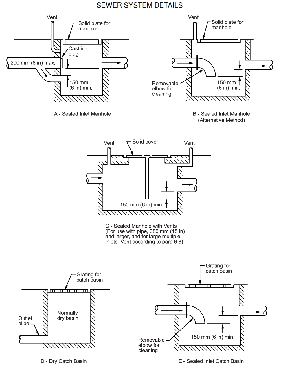
6.6.1 Fire seals shall be individually installed on each drain to prevent spread of fire in wastewater and
stormwater sewer systems. The preferred method is to seal the inlet pipe in the downstream manhole (see
Figure 5). This method permits displacement of accumulated oil into the sewer system. The seal shall
provide a minimum of 150 mm submergence below the lowest liquid level. P- or U-traps shall be used at the
drain hub where two or more equipment and pump drains are connected to the same sublateral, or where
the sublateral is tied into a lateral or main without a manhole with a water seal.
6.6.2 On sewer mains between process units, fire sealed cleanout manholes shall be provided to prevent
flame fronts from moving through partially filled sewers.
6.6.3 Seals shall be provided at strategic points along stormwater ditches and at tie-in connections to the
wastewater sewer to prevent spread of fire into other areas .
FIGRE 5
SEWER SYSTEM DETAILS
6.7 Cleanouts
Requirements for cleanouts are as follows:
a. Cleanouts shall be provided when the sewer turns through 90 degrees. They shall also be provided
when the sewer turns through 45 degrees and is preceded by a straight run of 15 m or more.
b. Cleanouts shall be installed to facilitate cleaning in the direction of flow.
c. Drain hubs may be considered as cleanouts if the run to the drain header is less than 6 m and total
turns do not exceed 135 degrees. This includes the 90 degree turn from vertical to horizontal.
d. In the absence of a manhole or catch basin, a cleanout shall be provided in every 60 m of straight
sewer run in lines NPS 12 and smaller.
e. Cleanouts shall be the same as the line size but shall not exceed NPS 6.
6.8 Vents
6.8.1 Manholes and sumps shall be provided with sealed covers and shall be vented to a safe location in
order to avoid hazards to personnel. The vent shall not be less than NPS 2” and shall not exceed NPS 4 in
line size. For wastewater sewers where flammable vapors may be present, the vent pipe shall terminate:
a. At least 3 m above any adjacent service platform.
b. A minimum of 6 m abovegrade.
c. At least 15 m measured horizontally from any fired heater or other source of ignition.
d. A minimum of 5 m from building air intakes or windows.
6.8.2 For stormwater and sanitary sewers and sumps, the vent line shall not be smaller than NPS 2 and it
shall terminate a minimum of 1 m abovegrade.
6.8.3 Vent pipes shall be designed to drain condensation back to the manhole or sump. Pressure/vacuum
vents may be installed to control odors from manhole vents in wastewater service.
6.9 Drainage Ditches
Drainage ditches may be used to collect stormwater and firewater, subject to the following limitations:
a. Drainage ditches shall not receive wastewater.
b. Drainage ditches shall not be used within process unit battery limits.
c. The location and design of drainage ditches relative to process equipment and piping should be
carefully considered to prevent the spread of fire. Fire stops shall be provided where deemed
applicable. Each fire stop shall consist of a sewer pipe with access sumps at each end for cleaning
and removal of silt and debris. The pipe shall be at least 10 m in length. A fire seal shall be provided at
the upper end sump. A flooded closed pipe under a road or rail crossing may also be used as a fire
stop.
d. Drainage ditches shall be separated from pipeways by a minimum horizontal distance of 3 m and
from process equipment by 10 m minimum. Where overhead and abovegrade hydrocarbon, firewater,
or utility lines cross over or are within 5 m of open drainage ditches, the overhead lines shall be
continuous pipe or welded joints. Pipe flanges or threaded connections or fittings are prohibited.
Pipeways crossing or within 5 m of drainage ditches shall be protected from fire by a concrete slab,
culvert, or by fireproofing the pipe rack or piping. Fireproofing shall consist of 50 mm of concrete or
other fireproofing material with a 1-hour, high-rise hydrocarbon fire rating.
e. For ditches constructed of reinforced concrete, the minimum size shall be 0.6 m wide and 0.5 m
deep. The depth shall not exceed the width.
f. Unlined earthen ditches shall have side slopes no steeper than 1.5 horizontal to 1.0 vertical, or
steeper than the angle of repose of the soil when wet. Where seepage is likely because of the varying
water level in ditches, side slopes of unlined earthen ditches shall not be steeper than 3.3 horizontal to 1 vertical. For concrete-lined ditches, side slopes shall be stable without the lining unless the lining is
designed to withstand resulting soil pressures. Requirements for sidewall surface treatment or other
special features shall be subject to Owner’s approval.
7. Safety
7.1 Existing documentation
7.1.1 Owner is responsible to provide and to assist with retrieval of all documentation required to identify all
existing underground obstructions, i.e. underground piping and sewers, electrical ductbanks, cables,
conduits, foundations, etc.
7.1.2 Exploratory trenching is to be performed where existing information is not available.
7.1.3 In the event that any obstructions are encountered during excavation, the Contractor shall stop work
in the area and notify Owner for identification of the obstruction and obtain directions before proceeding
further in that area.
7.2 Excavation and trenching
7.2.1 The stability of all excavated faces is to be maintained in compliance with specified excavation safety
standards through final acceptance of the Work.
7.2.2 Safety barricades shall be provided around all excavated areas until the Work is completed.
8. Materials Selection
8.1 General
Selection of materials for underground sewers and drainage pipes shall take into account such factors as
the temperature, chemical composition, physical properties of the wastewater, soil conditions, seismic
potential, pipe joint integrity, durability, cost, and availability. Piping materials shall be limited carbon steel,
corrugated steel, high density polyethylene, fiberglass reinforced epoxy, and reinforced concrete pipe.
These materials and their associated components, are specified in line classification Specification
SES P04-S01.
8.2 Piping Materials
8.2.1 Carbon Steel Pipe
Carbon steel pipe is recommended for use within battery limits of process units. Such pipe shall be
externally coated/wrapped and cathodically protected in accordance with 00-E-0043, 00-E-0045, and
00-E-0046. Depending upon the specific service conditions, the pipe may also require an internal
liner/coating. Carbon steel pipe shall also be used inside buildings, under asphalt and concrete pavements,
under foundation slabs. It shall extend a minimum of 2 m beyond the edges of buildings or foundations.
Carbon steel pipe shall not be used for corrosive chemical sewers.
8.2.2 Corrugated Steel Pipe
Corrugated steel pipe may be used for surface drainage culverts.
8.2.3 Ductile Iron Pipe
Ductile iron pipe may be used within or outside the battery limits with owner’s approval where corrosion or
temperature requires it.
8.2.4 Polyvinyl Chloride Pipe (PVC)
PVC may be used within or outside the battery limits with owner’s approval where corrosion requires it.
8.2.5 High Density Polyethylene (HDPE) Pipe
HDPE pipe may be used within battery limits of process units. HDPE pipe shall not be used in systems
where temperatures may reach in excess of 70°C.
8.2.6 Reinforced Thermosetting Pipe (RTR)
RTR pipe may be used within battery limits of process units, subject to Owner’s
approval. FRE pipe shall not be used in systems where temperatures may exceed 120°C.
8.2.7 Reinforced Concrete Pipe (RCP)
RCP is recommended for stormwater drainage and wastewater sewers outside battery limits; however,
alternative piping materials may be used with Owner’s approval. RCP shall be per Class IV, ASTM C76M.
9. Installation
9.1 General
9.1.1 Installation of underground piping for sewer systems should address the following:
a. Bedding/support for pipe in its trench.
b. Required depth of cover (especially under roadways).
c. Backfill material and compaction (if required).
9.1.2 Carbon steel piping shall be installed in accordance with SES P02-S01.
9.1.3 Joining methods used for installing HDPE and FRE piping shall be approved by Owner. Personnel
involved in the installation of HDPE and FRE piping shall be tested and qualified according to
manufacturer’s requirements to confirm their capability to install a leak-tight joint.
NOTE: Due to various grades of HDPE and FRE available, testing/qualifying should be
done using the specific product being installed.
9.2 Cover
Sewer lines shall have a minimum depth of 0.5 m within process unit battery limits. The cover shall be
measured from the finished surface to the outside top of pipe. For offsite areas, sewer lines shall be at or
below a minimum of 1 m. These requirements apply to process and utility lines also.
9.3 Line Protection
Under roadways and vehicle-traveled areas, sewer lines requiring protection shall be encased in a concrete
envelope or in a sleeve providing a 75 mm minimum total clearance. Alternatively, these lines shall be
covered with a load-bearing steel plate or concrete slab. These requirements apply to process and utility
lines also.
9.4 Laying Pipe
9.4.1 Pipe shall be protected during handling against impact shocks and free fall. Proper facilities shall be
provided for lowering the sections of pipe to prevent disturbances of the bed and sides of the trench.
9.4.2 The pipe shall be carefully laid, starting at the downstream end, with the tongue or spigot end pointing
in the direction of flow. Pipe shall be kept clean at all times.
9.4.3 Pipe shall be set firmly according to line and grade. Prior to making joints, all surfaces shall be
thoroughly cleaned and prepared as required for the type of joint to be made. Pipe shall be carefully
centered so that the completed sewer will have a smooth uniform invert.
9.4.4 The barrel of the pipe shall be in contact with the quadrant shaped bedding throughout its full length,
exclusive of the bell.
9.4.5 To prevent shear failure the branches of all fittings shall be supported by granular material backfilled
in the trench to provide support equal to that furnished the barrel of the pipe.
9.4.6 A minimum 300 mm shall be kept clear shell to shell of lines parallel and lines crossing each other.
9.5 Jointing and Finishing
9.5.1 Joints shall be made tight to prevent excessive infiltration or exfiltration. Testing shall be as specified
on the project drawings and specifications and as described herein.
9.5.2 At all joints not using a flexible gasketed joint (push-on), the inside surface of the pipe shall be
cleaned after the joint is made and each section shall be swabbed to prevent the joint material from
projecting into the pipe. When pipe laying is suspended for any cause, the ends of the pipe shall be kept
closed to keep out dirt, mud and foreign substances. Adequate provision shall be made to prevent floating
of pipe in the event the trench is flooded.
9.6 Culverts
9.6.1 Multiple installation of pipes shall be laid with the center line of individual barrels parallel. Unless
otherwise indicated in the design drawings, the clear distances between outer faces of adjacent pipes shall
be as follows:
Nominal Inside Diameter of Pipe Clear Distance Between Pipes
18” and under 230 mm
2” and 24” 280 mm
27” and 30” 330 mm
33” and 36” 380 mm
36” and 42” 430 mm
9.6.2 Corrugated metal pipe shall be laid with the separate sections joined firmly together and without side
laps or circumferential joints pointing upstream and with longitudinal laps on the sides.
9.6.3 If paving of inverts, or bituminous coating, or bituminous lining is specified for corrugated metal pipe,
it shall be in accordance with the provisions of AASHO Designation M190, “Standard Specifications for
Bituminous Coated Corrugated metal Culvert Pipe and Pipe Arches.”
9.6.4 If headwalls or flared end sections are not required for corrugated metal pipe, the ends of all 14- and
16-gage installations shall be reinforced. Reinforcement shall consist of a galvanized steel rod not less than
11 mm diameter rolled in the sheet, or by a galvanized metal bond equivalent in cross-section to 9.5 mm
thick by 38 mm wide, or by increasing the outer one foot of 16-gage or 14-gage pipe to at least 12-gage
material. Bands shall be fastened to the pipe at maximum intervals of 250 mm on each edge of the band.
9.6.5 Culverts without headwalls or flared end sections, and located so that the culvert invert is at the toe of
a slope, shall be installed so that the end of the culvert will extend at least one foot beyond the toe of slope.
Culverts located so that the invert of the culvert is above the toe of a slope at the discharge end, shall be
protected against erosion by headwalls, flared end sections, rip-rap or similar methods, as shown on the
drawings or as approved by Engineer.
9.6.6 All backfill for culverts shall be selected fine compressible material, such as silty clay or loam, and
shall not contain stones or lumps or earth over 76 mm in largest dimensions. Backfill material shall be
compacted in maximum 150 mm layers to the density specified for the surrounding embankment or fill.
Water tamping of backfill will not be permitted. A granular backfill may be used for all but the outer 915 mm
at both ends of the culvert. The ends shall be backfilled with selected fine compressible material.
9.7 Testing
9.7.1 General
9.7.1.1 All sewer systems shall be water tested before and after backfilling for water tightness. Water tests
before backfilling reveal cracked or porous pipes and faulty joints. The water tests also show whether or not
the finished work meets the specified water tightness requirements. Water tests applied after backfilling
reveal faults in the bedding or the support of the pipe, inadequacies in design or accidental damage during,or subsequent to, backfilling, and may show whether or not the finished work meets the specified
watertightness requirements. Any piping that fails shall be uncovered and replaced or repaired.
9.7.1.2 Wherever possible, testing should be carried out from manhole to manhole. Short branch drains
connected to a main sewer between manholes should be tested as one system with the main sewer. Long
branches should be tested separately from manholes.
9.7.2 Water Test
9.7.2.1 Drains and sewers shall be subjected to an internal pressure test with a head of water at least 1.5 m
above the crown of the pipe at the high end, but not more than 6 m at the low end. Steeply graded sewers
shall be tested in stages if the 6 m maximum head limitation would be exceeded should the whole section
be tested at the same time. A standpipe shall be employed to ascertain that the specified head is obtained.
9.7.2.2 Since some piping materials absorb more water than others, and some piping configurations trap
more air at the joints than others, an allowance can be made by adding water to maintain the test head for
appropriate periods. The test should be started approximately one hour after filling the pipe with water.
9.7.2.3 The loss of water over a period of 30 minutes shall be measured by adding water from a measuring
vessel at 10-minute intervals and noting the quantity required to maintain the original water level. For this
test, the average quantity added shall not exceed 1.0 liter per hour per 100 meters linear distance per
centimeter of nominal internal sewer diameter. However, if local codes are more stringent, they shall be
followed.
9.7.2.4 Pipe leakage that causes a drop in the test water level will be apparent by the change in the water
level in the standpipe. Any leaks visible during water testing shall be corrected. Defective parts of the sewer
system being tested shall be removed, replaced, and retested.