1. SCOPE ………………………………………………………………1.1
Potential Services
2. REFERENCES
3. DEFINITIONS ……………………………………………………..4. GENERAL REQUIREMENTS
4.1 Design Conditions
4.2
Service Considerations ……………………………………
4.3
Properties Required for System Design
4.4
Allowable Axial Stress
5. PIPING SYSTEM DESIGN
5.1 General
Design
Considerations
5.2
Underground Pipe Analysis
6. DESIGN REPORT REQUIREMENTS …………………….6.1
Summary of Design Conditions and Assumptions
6.2 Qualification of Pipe and Components
6.3
Calculation Package ……………………………………….
6.4
Drawings
6.5
Data
APPENDIX
A Design Condition Summary …………………………………..
1. Scope
This standard is for design of underground fiberglass reinforced plastic (FRP) piping systems and
components for use in SABIC facilities.
The requirements described herein apply to a variety of commodity and custom pipe systems utilizing
glass fiber reinforced composite laminates in typical services, as detailed below. Services, design
conditions, and pipe materials or manufacturing methods not described herein are considered outside the
scope of this standard.
1.1 Potential Services
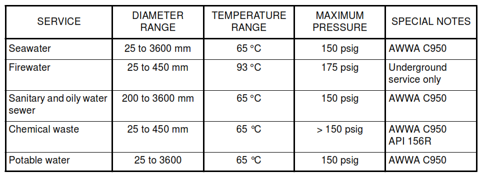
The requirements of this standard are intended for use in the design, manufacture and installation of FRP
piping used in the following services. Typical services are summarized in the following table.
2. References
Reference is made in this standard to the following documents. The latest issue, amendments and
supplements to these documents shall apply unless otherwise indicated.
SABIC Engineering Standards (SES)
P01-E04 Flexibility Requirements and Stress Analysis of Above Ground and Plant Piping Systems
P13-C05 Installation Requirements for FRP Piping Systems
P14-T01 Quality Assurance of FRP Piping
Z05-S01 General Procurement Guidelines
American Society for Testing and Materials (ASTM)
C 581 Chemical Resistance of Thermosetting Resins used in Glass Fiber Reinforced Structures
D 638 Test Method for Tensile Properties of Plastics
D 695 Test Method for Compressive Properties of Rigid Plastics
D 696 Test Method for Coefficient of Linear Thermal Expansion of Plastics Between -30 °C and 30 °C
D 698 Standard Test Methods for Moisture-Density Relations of Soils and Soil-Aggregate Mixtures
Using 5.5 lb (2.49 kg) Rammer and 12 in (305 mm) Drop
D 790 Standard Test Methods for Flexural Properties of Unreinforced and Reinforced Plastics and
Electrical Insulating Materials
D 792 Standard Test Methods for Density and Specific Gravity (Relative Density) of Plastics by
Displacement
D 883 Standard Terminology Relating to Plastics
D 1559 Standard Test Method for Short-Time Hydraulic Failure Pressure of Plastic Pipe, Tubing,
and Fittings
D 2105 Standard Test Method for Longitudinal Tensile Properties of “Fiberglass” (Glass-Fiber-Reinforced
Thermosetting-Resin) Pipe and Tube
D 2143 Standard Test Method for Cyclic Pressure Strength of Reinforced, Thermosetting Plastic Pipe
D 2412 Standard Test Method for Determination of External Loading Characteristics of Plastic Pipe by
Parallel-Plate Loading
D 2487 Standard Test Method for Classification of Soils for Engineering Purposes
D 2584 Standard Test Method for Ignition Loss of Cured Reinforced Resins
D 2924 Standard Test Method for External Pressure Resistance of Reinforced Thermosetting-Resin Pipe
D 2925 Standard Test Method for Beam Deflection of “Fiberglass” (Glass-Fiber-Reinforced
Thermosetting-Resin) Pipe Under Full Bore Flow
D 2992 Standard Practice for Obtaining Hydrostatic or Pressure Design Basis for “Fiberglass”
(Glass-Fiber -Reinforced Thermosetting-Resin) Pipe and Fittings
D 3517 Standard Specification for “Fiberglass” (Glass-Fiber-Reinforced Thermosetting-Resin) Pressure
Pipe
D 4161 Standard Specification for “Fiberglass” (Glass-Fiber-Reinforced Thermosetting-Resin) Pipe Joints
Using Flexible Elastomeric Seals
D 4255 Standard Guide for Testing In-plane Shear Properties of Composite Laminates
American Society of Mechanical Engineers (ASME)
B31.3 Chemical Plant and Petroleum Refinery Piping
RTP-1 Reinforced Thermoset Plastic Corrosion Resistant Equipment
American Water Works Association (AWWA)
C950 AWWA Standard for Fiberglass Pressure Pipe
M45 Manual of Water Supply Practices Fiberglass Pipe Design
Other References
BS 7159 British Standard Code of Practice for Design and Construction of Glass Reinforced Plastic (GRP)
Piping Systems for Individual Plants or Sites
UKOOA UK Offshore Operators Association Specification and Recommended Practice for the use of
GRP Piping Offshore
3. Definitions
For the purpose of understanding this standard, the following definitions apply.
Axial. The longitudinal axis of the pipe.
Bi-axial Pressure. Pressure which is restrained by the pipe and exerts both hoop and axial stress in the
pipe wall.
Commodity Pipe. FRP pipe manufactured in standard sizes and classes for general use.
Contractor. The party responsible for all or part of the design, engineering, procurement, construction and
commissioning for a project.
Corrosion Liner. The thickness of the non-structural layer(s) on the interior of the pipe wall laminate
intended to resist degradation by the service fluid, thereby protecting the structural laminate. The pipe wall
laminate typically consists of the corrosion liner plus the structural wall.
Custom Pipe. FRP pipe manufactured for project specific requirements.
Designer. General term referring to the party employed or contracted by the Contractor for design of the
piping system.
Fixed Pipe Region. That portion of underground piping which is restrained from axial movement by soil
friction.
Flexibility Factor. Constant used in piping flexibility analysis to define the relative flexibility of a bend or
tee to that of the pipe.
HDB. Hydrostatic Design Basis, determined by testing in accordance with ASTM D 2992.
HDS. Hydrostatic Design Stress, maximum allowable hoop stress determined by the limits of this standard.
Hoop. Circumferential direction in the pipe.
Lamination Theory. Mathematical procedure for determining stress and strain in individual layers, as well
as estimating material properties, of a composite laminate.
Manufacturer. The party which manufactures FRP pipe and components and is responsible for the
qualification testing of the product.
Material Manufacturer. The supplier of the raw materials used for manufacturing of the FRP pipe and
components.
Moving Pipe Region. That portion of underground piping which is near bends or tees and is not
completely restrained from axial movement by soil friction.
Native Soil. The soil which exists in the area of the underground pipe installation.
Orthotropic. Term used to characterize the directional behavior of most composite pipe laminates.
Pipe Stiffness. A specific value relating to the hoop stiffness of a given pipe design or product, per
ASTM D 2412.
Ring Bending Strain. Strain induced in the underground pipe by soil overburden and live loads.
Shear Collar. An FRP laminate applied to the exterior of the pipe adjacent to anchors or other pipe
supports for the purpose of transferring axial pipe loads into the supporting structure.
SIF. Stress Intensification Factor, a constant used in flexibility analysis defining the relative stress in a
bend or tee to that of the pipe.
STHS. Short Term Hydrostatic Strength, hoop stress determined by testing per ASTM D 1599.
Structural Wall. The thickness of the pipe wall laminate which is reinforced and provides load bearing
capability, but does not include the corrosion liner thickness. The pipe wall laminate typically consists of
the corrosion liner plus the structural wall.
STUS. Short Term Ultimate Strength, the ultimate strength of a composite laminate determined by coupon
testing per ASTM D 638.
Tied Length. That length of underground pipe near corners where joints are designed to carry the axial
pipe load; approximately equal to the length of the Moving Pipe Region.
Virtual Anchor. The theoretical point in underground pipe between the Moving Pipe Region and the Fixed
Pipe Region. The virtual anchor point is some distance away from a bend or tee, where soil friction
overcomes axial pipe loads and the pipe becomes locked in the soil.
4. General Requirements
These requirements apply to the selection, qualification and manufacture of all FRP pipe and components,
and design of the piping system.
4.1 Design Conditions
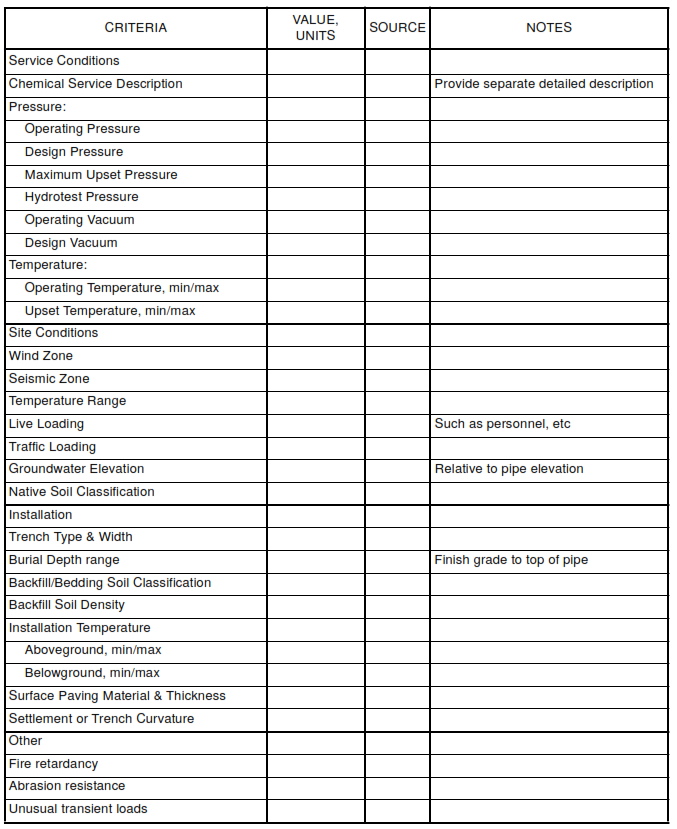
All design conditions shall be documented and summarized for use by the project, using the Design
Condition Summary form included in the Appendix, or similar format. It is the Contractor’s responsibility to
identify all conditions that could potentially affect the selection of materials or design of the piping system.
As a minimum, the following conditions shall be considered.
4.1.1 Pressure
a. Operating Pressure. The normal operating pressure range anticipated on a continuous basis
over the long term.
b. Design Pressure. The pressure agreed to be used for selection and qualification of the pipe and
components. Design pressure is typically higher than the operating pressure in order to include surge
pressure or other common events anticipated routinely over the life of the system. Rare or unlikely
conditions of short duration are considered transient and are not required to be included in the design
pressure.
c. Maximum Upset Pressure. The maximum pressure that the piping system could experience
infrequently and for short duration, under any combination of conditions, including rare or unlikely
transient conditions.
d. Hydrotest Pressure. The pressure used for static hydrotesting of the system after installation.
Hydrotest pressure shall not exceed 150% of the design pressure.
4.1.2 Vacuum
a. Operating vacuum. The normal operating vacuum pressure range anticipated frequently in the
system.
b. Design vacuum. The vacuum pressure agreed to be used for selection and design of piping and
components. Must include the highest vacuum pressure anticipated due to any combination of
conditions, including valve closure or other event in any part of the system.
4.1.3 Temperature
a. Operating temperature. The normal temperature range anticipated on a continuous basis over
the long term.
b. Upset temperature. The maximum and minimum temperature that the piping system could
experience infrequently and for short durations, under any combination of conditions.
c. Ambient temperature. The range of climatic conditions under which the system is expected to
operate.
d.
Installation temperature. The range of ambient temperatures anticipated during the piping system
installation period.
4.1.4 Wind and Earthquake Loads
Any wind or seismic load conditions specified for the project or required by local authorities.
4.1.5 Burial Conditions
Due to the interactive nature of burial conditions and the underground pipe design, it may prove beneficial
to change various aspects of the installation to reduce overall installed pipe cost. Commonly available
backfill materials and routine procedures may be specified initially, but the underground pipe design should
be an iterative process which considers the combined effect of installation costs vs. pipe manufacturing
cost.
a. Depth of burial. Minimum and maximum distance from finished grade to the top of the pipe.
b. Trench type and width. Identify whether trenches will be cut through native soil, or whether pipe
will be placed and then buried embankment style. For cut trenches, total trench width shall be
identified for each diameter of pipe.
c. Native soil classification. Determine native soil type in accordance with the Uniform Soil
Classification system per ASTM D 2487, and in the format required for use by AWWA M45.
d. Backfill and bedding material. Identify type of material and compaction level to be used for
bedding and backfill of the pipe, in accordance with the Uniform Soil Classification system and in the
format required by AWWA M45.
e. Backfill density. Unit weight of backfill material.
f. Ground water elevation. Determine maximum height of the water table in the area of the piping
system, relative to piping elevation.
g. Surface paving. Identify type and thickness of surface paving to be installed at grade over the
piping system.
h. Settlement or trench curvature. Identify the anticipated settlement of structures connected to the
piping system or located over or adjacent to the pipe. Identify any anticipated differential settlement of
the soil foundation under the pipe, and the trench length over which the settlement would occur.
4.1.6 Live Loads
Identify non-continuous loads applied to the piping system as a result of personnel, vehicular traffic,
construction loads, railroad crossings, temporary storage over the pipe, etc. Live loads may vary for
specific areas of the piping system.
4.1.7 Other Conditions
Identify any unusual loads which the equipment must sustain. These might include excessive vibration or
cyclic loads, surge pressures, etc.
4.2 Service Considerations
Selection of materials, manufacturing methods and design features must consider the specific service
requirements of the system. Special materials, additives or increased corrosion liner thickness may be
required to properly address these issues and provide for protection of the structural laminates over the
service life of the system. The Design Report shall include information as required to provide the basis for
how these issues are addressed.
4.2.1 Chemical Resistance
Although liner construction, cure, and fabrication method can influence chemical resistance, the chemical
resistance of FRP pipe depends primarily on the particular resin used. Resins are available that provide
chemical resistance to a wide range of specific chemical services.
Stress, aging, and temperature effects in the chemical environment should be considered as part of the
FRP pipe qualification and design procedures. In general, chemical resistance is reduced at higher
temperature and stress levels.
The FRP pipe manufacturer should provide performance documentation in the form of case histories and
recommendations based on ASTM C 581 testing from resin manufacturers for each application.
4.2.2 Temperature Resistance
The temperature resistance of FRP pipe also depends largely upon the resin used. The chemical
environment and the level of stress influence the upper limit of service temperature in the piping system.
In general, the properties of FRP pipe are reduced with increasing temperature. Each resin will perform
differently at elevated temperature. Information is readily available from resin manufacturers that will allow
pipe properties to be derated during design.
4.2.3 Abrasion Resistance
FRP pipe generally has good abrasion resistance and can be custom made for extreme services by
adding very hard particulate fillers to the resin, using carbon fibers and veils on the inner surface of the
corrosion liner, or by incorporating resilient liner materials such as polyurethane.
The abrasiveness of the service should be evaluated during design and any special lining material that is
used should exceed the hardness of the contents being transported through the pipe or provide a very
high level of toughness and resilience.
4.2.4 Fire Resistance
All resins used in manufacturing FRP pipe will burn when exposed to fire. For many years flame retardant
compounds have been added to resins or protective coatings have been applied to improve fire resistance
and reduce flame spread rates. More recently the issue of fire resistance has evolved into fire endurance.
The fire endurance of a piping system is the capability to maintain its strength and integrity for some
predetermined period of time while exposed to fire and its ability perform its intended function after the fire.
Levels of endurance considering the severity and consequences resulting from the loss of system integrity
for various applications have been employed to specify fire resistance for FRP piping systems.
One of the most commonly used requirements for FRP pipe is IMO (International Maritime Organization)
Level 3 fire endurance rating. A Level 3 endurance rating requires that the pipe survive a local fire of short
duration and that its function is capable of being restored after the fire has been extinguished.
When fire resistance, including flame spread, level of endurance, smoke generation and toxicity for a
piping system is required, the piping manufacturer should be consulted and documentation provided
regarding their specific products fire resistance.
4.3 Properties Required For System Design
The following information for each component shall be provided for use in design of the piping system.
Some properties will result from the qualification testing but additional testing or approved analysis will be
required to determine all necessary properties.
Laminate analysis programs which utilize lamination theory may be used to predict modulus values and
Poisson ratios for use in system analysis. The basis for the properties must be provided and must include
verification by testing of input values. If requested, full testing as discussed below shall be performed.
Strength values must be determined by testing.
The coefficient of linear thermal expansion is non-linear and must be determined by testing for the
temperature range of interest.
Adjustments to the strength and modulus properties for temperature retention may be performed
analytically.
4.3.1 Coefficient of Linear Thermal Expansion
The Coefficient of Linear Thermal Expansion (CLTE) may be obtained by testing the final product in
accordance with ASTM D 696. Alternate methods of determining the CLTE may be employed if shown to
be applicable and approved. CLTE should be determined for the axial and hoop direction, at temperatures
representative of the design and operating temperatures of the specific system.
4.3.2 Axial Tensile Modulus of Elasticity, Strength and Poisson Ratio
The Axial Tensile Modulus of Elasticity may be obtained by testing the final product in accordance with
ASTM D 2105 or by coupon testing in accordance with ASTM D 638. Poisson ratio shall determined during
this testing by applying strain gages and measuring the hoop reaction to the applied axial tensile load.
4.3.3 Axial Flexural Modulus of Elasticity
The Axial Flexural Modulus of Elasticity may be obtained by testing the final product similar to the
procedures in ASTM D 2925. The testing may be performed at ambient temperature and without water as
these conditions are considered elsewhere in the piping system design. Coupon testing in accordance with
ASTM D 790 may be substituted if shown to be applicable and representative of the whole pipe.
4.3.4 Axial Compressive Modulus of Elasticity
The Axial Compressive Modulus may be obtained by testing the final product in accordance with
ASTM D 695.
4.3.5 Hoop Tensile Modulus of Elasticity and Poisson Ratio
The Hoop Modulus of Elasticity and Poisson ratio shall be determined by methods which apply only a hoop
tensile stress and allow axial contraction due to the Poisson effect. In this way, hoop tensile modulus and
Poisson ratio can be correctly determined. Procedures for testing in this manner are described in UKOOA,
Annex B.
4.3.6 Hoop Flexural Modulus of Elasticity
The hoop flexural modulus may be determined from the ASTM D 2412 testing used to qualify the pipe or by
coupon testing according to ASTM D 790. This value is required only for underground pipe analysis.
4.3.7 Density
The density may be obtained by testing the final product in accordance with ASTM D 792 or by analysis
based on published values for the component materials.
4.3.8 In-Plane Shear Modulus of Elasticity
The In-Plane Shear Modulus of Elasticity may be obtained by testing the final product in accordance with
ASTM D 4255 or by analysis based on published values for the component materials.
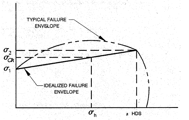
4.4 Allowable Axial Stress
The allowable axial stress at any point in the system will vary with the ratio of hoop to axial loading. The
following sections identify the procedure to be used for determining the allowable axial stress under
combined loading conditions.
4.4.1 For all aboveground and underground pressure pipe, determine the allowable axial stress under 2:1
bi-axial pressure loading:
σ2 = (HDS) / 2 ————————– equation 1
Where:
σ2 = allowable axial stress under 2:1 bi-axial loading
HDS = hydrostatic design stress
4.4.2 For all pipe, determine allowable axial stress when no pressure exists:
σ1 = σult /5 ——- Equation 2
Where:
σ1 = allowable axial stress at pressure = 0
σult = ultimate axial stress (see SES P01-E28-01)
4.4.3 For pressure piping, determine allowable axial stress under combined loading conditions:
σax = σ1 + (σ2 – σ1 )σh / (HDS ) Equation 3
Where:
σax = allowable axial stress under combined loading conditions
σ1 = allowable axial stress at pressure = 0, (per 4.4.2)
σ2 = allowable axial stress under 2:1 bi-axial loading, (per 4.4.1)
σh = hoop stress under applied design loads, (see SES P01-E28-01)
HDS = hydrostatic design stress, (see SES P01-E28-01)
For non-pressure piping, σax is equal to σ1 from 4.4.2, as other hoop loads are ignored.
The allowable axial stress is represented under various loading combinations by the following graph:
5. Piping System Design
The design of FRP piping systems shall provide for the most severe coincident condition of temperature,
pressure and other loads. Where two or more distinct conditions occur, they must be separately evaluated
using the applicable temperatures, pressures and loadings for each case. The most severe conditions for
pressure containment may differ from those for system flexibility.
5.1 General Design Considerations
5.1.1 Properties and Allowables
Properties and allowable stresses used in analysis of the piping system shall be as developed and
documented during qualification of the product being used. In addition, adjustments shall be made as
necessary to properly represent the system, including the following as a minimum.
a. Properties shall be adjusted to account for operation at elevated temperature. Since it is not
practical for qualification testing to be performed at the operating temperatures of many systems,
adjustments may be made to the modulus and allowable strength values based on other data.
Applicable test data is available from material manufacturers for retention of properties of standard
hand layup laminates, which can be used to estimate design values.
b. Allowable stresses may be increased for short term transient loads, including seismic, wind,
hydrotest pressure, and other rare or unlikely events. Allowable stresses may be increased by 30% for
these loads.
c.
If corrosion or abrasion due to contact with the service liquid is anticipated, the loss of thickness
and potential strength degradation must be anticipated in the design of the system. Typically, the
corrosion liner thickness is increased to extend the time before the structural laminates are
compromised. In this case, the corrosion liner thickness exceeding that present during the
qualification of the piping components shall be considered sacrificial and not included for structural
contribution. For the system stress analysis, it may be necessary to include the additional thickness
for its weight and stiffness contribution only.
d. An appropriate thickness shall be used for fittings, based on the specific manufacturing method.
Fittings often have localized thickness differences due to manufacturing procedures which must be
recognized and utilized in a conservative manner.
5.1.2 Layout Considerations
a. General
Layout of FRP piping systems is similar to that of other piping materials. However, the nature of FRP
requires that certain issues be resolved during the design. Differences required in layout design
originate from two basic issues.
(i) FRP piping has roughly twice the expansion rate of steel, and this additional growth/contraction
must be anticipated.
(ii) The joining systems for FRP piping systems require more distance between fittings, joints and
supports to allow for butt and strap joint overlays, socket type joints, etc.
b. Where practical, piping layout should be a flexible system that allows thermal
expansion/contraction and does not constrain the pipe between anchors. This will avoid high anchor
loads and prevent axial buckling problems in compressed pipe runs.
c. Proximity to other Pipes and Structures
The designer shall consider any potential detriment to FRP pipe due to leakage or thermal effects
from other nearby pipes. Allow clearance for expansion and contraction of the pipe. Underground,
allow for minimum bedding and clearances to adjacent structures, in accordance with P13-C05.
d. Pipeline Slope
Pipelines carrying gravity flows must be sloped sufficiently to drain while accounting for deflection
between supports. Piping with varying elevations shall be designed to accommodate the pressure
increase due to hydrostatic head.
e. Anchors and Thrust Blocks
The piping system must be designed with sufficient means to transmit accumulated loads to the
ground or support system. Thrust forces develop at changes in direction of the pipe due to internal
pressure. Anchor loads develop when thermal expansion of a pipe is prevented. Anchors and thrust
blocks must be designed to mechanically restrain the pipe as intended and have sufficient mass to
prevent movement.
f. Field Joints
Placement of field joint locations shall consider handling, maximum shipping lengths, field adjustment
needs, and accessibility.
5.1.3 Loads Cases and Combinations
The following minimum load combinations shall be analyzed for the piping system. These are basic
guidelines and may not include all of the appropriate or the most severe load combinations possible in any
specific system. It is the responsibility of the Contractor to identify and resolve all of the loads and
appropriate combinations.
a. Thermal displacement
Pipe displacement due to positive or negative changes in temperature, when considered in
combination with internal pressure, is typically the most severe loading condition. Two thermal
displacement cases shall be considered, combined with other loads as required to determine
maximum stress:
(i) Hot case. Maximum thermal expansion due to the change from the minimum installation
temperature to the maximum operating temperature.
(ii) Cold case. Maximum thermal contraction due to the change from the maximum installation
temperature to the minimum operating temperature.
b.
Internal pressure
The design pressure shall be considered in combination with both the Hot and Cold cases.
Since internal pressure may enhance the axial allowable stress, the zero pressure case must also be
considered in combination with both the Hot and Cold cases.
c. Transient loads
Wind and seismic loads are considered transient and are permitted an increased allowable stress.
Apply these loads in principal directions and in combination with the most severe combination of other
loads.
Excursions beyond the operating temperatures are considered transient, with an increased allowable
stress. If excursions are significantly above operating temperatures, the maximum displacements
should be checked to assure there is no interference with adjacent equipment or structures.
Hydrotesting at increased pressure is also considered transient, and should be analyzed in
combination with an appropriate temperature.
5.1.4 Other Considerations
a. Vibration Prevention
Vibration at any amplitude has the potential to cause serious damage to FRP piping systems and
must be addressed by the designer. Vibration at low amplitude may become significant if the natural
frequency of the piping system is such that resonance with the source of the vibration occurs. Damage
can be caused by overstressing of the pipe, contact with adjacent equipment, or abrasion at supports.
Vibration can be resolved by isolation of the source with flexible connections, or by adjustments to the
support types and positions.
b. Loads on Equipment Nozzles
Where FRP components are connected to process equipment nozzles, the designer must consider
the effect of the pipe on the equipment as well as the effect of the equipment on the pipe. Nozzles
must be reinforced as necessary to accommodate the forces rendered by the pipeline being
connected. Most equipment suppliers can provide allowable nozzle loads for use in the analysis.
c. Pipelines Crossing under Roads
Where the pipeline cannot be installed with adequate cover to withstand the anticipated live loads,
consideration shall be given to installing the pipe within a casing. The casing may be steel or other
suitable material. Piping shall be checked for axial buckling between support skids inside of casings
per P01-E28-02.
5.2 Underground Pipe Analysis
5.2.1 General
FRP pipe is heavily dependent upon the surrounding soil to provide the support necessary to resist the
applied loads from overburden and external pressure. In designing an FRP underground piping system it is
important to design and specify the installation and the supporting soils in conjunction with the pipe design
to achieve satisfactory long-term performance. It may prove beneficial to change various aspects of the
installation to reduce overall installed pipe cost. The design of the underground pipe should be an iterative
process which considers the combined effect of installation costs vs. pipe manufacturing cost.
The design approach is semi-empirical in which the influence of loading and pipe-soil interaction is
determined by the proper selection of several simplified parameters. High confidence is maintained only
when actual conditions are similar to those incorporated in the design.
The design of underground FRP pipe requires the use of both rigorous and empirical methods utilizing
manual and computer analysis techniques. In the process of designing the pipe, the evaluation of the
native soil and site conditions, key parameters that determine installation methods, and embedment of the
pipe are selected.
The design methods discussed apply to pipe with uniform walls that do not employ stiffening ribs as a
means of achieving pipe stiffness and controlling hoop deflection and stresses. For design of pipe with
ribbed walls some of the equations must be modified to account for the ribbed cross-section and additional
calculations are necessary.
In determining the applied loads and the response of the pipe to underground conditions AWWA M45
should be used in conjunction with the guidelines discussed in this standard.
5.2.2 Additional underground loads and parameters
In addition to loads resulting from the operating conditions of pressure and temperature there are several
installation parameters associated with underground pipe that result in loads and determine it’s long-term
performance. Since these parameters reflect the conditions at the site and the intended installation
methods, selecting these parameters is the initial step in the design process.
The following defines these parameters and gives reference to the applicable sections of AWWA M45.
a. Trench Width
Trench width determines the influence of the native soil. In narrow trenches where the trench width is
less than 3 x Diameters the supporting soil envelope can be either be strengthened or weakened
depending on the relative stiffness of the native soil and the compacted backfill material. (Reference
AWWA M45, Section 5.7.3.8 and 6.61)
b. Native Soil Classification
To determine its contribution of support for the pipe, the native soil must be defined. Typically, the
native soil can be described as either granular or cohesive material and the blow count from standard
penetration tests or the unconfined compressive strength are required as a minimum to estimate the
properties required for analysis. (Reference AWWA M45, Table 5-6 and Section 6.4)
c. Groundwater
The maximum groundwater elevation expected in the pipe zone is required to determine external
hydrostatic pressure used in buckling analysis of the pipe. In some installations the presence of
groundwater can require the use of a geotextile filter fabric to prevent migration native soils into select
backfill in the pipe zone. (Reference AWWA M45, Section 5.7.5)
d. Burial Depth
The depth at which the pipe is buried determines loads from soil overburden and the magnitude of
live loads transferred to the pipe from vehicular traffic at the surface. The minimum and maximum
depths should be used in the analysis to bound the range of combined live and soil overburden loads.
The pipe elevation can be compared to boring logs from geotechnical investigations showing the
strata and stiffness of the native soils at various depths aiding in determination of the degree of
support provided by the native soil. Resistance to buckling from external hydrostatic pressure and to
uplift from buoyant forces are also influenced by the burial depth. (AWWA M45, Sections 5.7.3.5,
5.7.3.6, and 5.7.5)
e. Settlement
Settlement of structures connected to or in the vicinity of the pipe require special attention and some
means to allow settlement without over-stressing the pipe must be provided. In some situations
additional reinforcing of the pipe is a solution. In many cases, particularly with large diameter pipe
(D>24”), flexible connections or backpacking the pipe with a cushion material are required.
f. Trench Curvature
Curvature of the trench bottom causes bending of the pipe and an axial load that must be considered
in the analysis. With small diameter pipe horizontal curvature from laying the pipe can be a concern.
The most common approach used to avoid additional axial stress is to ensure that directional
changes occur at joints during installation of the pipe, (AWWA M45, Section 5.8).
g. Live Loads
Live loading from vehicular surface traffic including loads from constructions equipment such as
cranes and from railroads are additive to soil overburden loads in the analysis of underground pipe.
Construction traffic is normally a transient condition and may not need to be combined with other
operational loads. In areas with frequent and large traffic loads the pipe is generally installed in a
casing to protect the pipe. The loads transferred to the pipe from construction traffic are relieved by
construction haul roads or by using protective matting to prevent short-term damage to the pipe,
(AWWA M45, section 5.7.3.6).
h. Backfill and Bedding Material
Several materials a suitable for bedding and backfilling FRP pipe. Pipe performance is critically
dependent upon the proper selection, placement, and compaction of these materials. Generally,
coarse grained materials containing few fines (passing 200 sieve) are preferred and require less
compactive effort to achieve the compaction density and stiffness required for support of the pipe. The
impact of bedding and backfill material selection on installation procedures, effort and pipe cost should
be considered in the initial stages of design. (AWWA M45, Sections 5.7.3.8 and 6.5)
5.2.3 Manual Techniques
a. General
FRP underground piping systems shall be analyzed to verify that the maximum stresses and strains
due to combined loading are within the allowable values derived in SES P01-E28-01 and 4.4. In
addition to the maximum combined axial stress the combined hoop stress from pressurization and
burial of the pipe must be determined.
The methodology in AWWA M45 should be used to determine the maximum combined hoop stress in
the pipe and the result compared to the allowable values as defined by this standard. The combined
axial stress should be determined by the manual calculations discussed below or by computer
modeling.
b. Assumptions
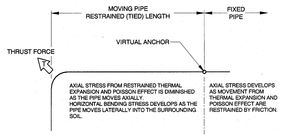
The underground piping system can be divided into two basic categories, fixed and moving pipe. The
axial movement of fixed pipe is completely restrained by friction between the pipe and soil. Fixed pipe
will typically comprise most of piping system between bends. Moving pipe is pipe near bends where
axial movement is not completely restrained by friction. The intersection of fixed and moving pipe is
the virtual anchor. The distance between the virtual anchor and bend is often called the restrained or
tied length in which joints allowing axial movement are not permitted without some means of thrust
restraint at the bend. See Section 7.5 in AWWA M45 and the following diagram.
Manual calculations are sufficient to determine hoop stresses in both areas of the piping system.
Axial stresses in fixed pipe regions of the piping system are also easily calculated by manual
techniques but, due to the complexity of soil restraining horizontal movement, the axial stresses in
moving pipe regions are best resolved using computer analysis. For the same reason, in areas where
settlement is expected, computer analysis is appropriate.
Pipe movement is considered to be completely restrained by friction so that thermal expansion and
contraction from the Poisson effect do not occur and axial stresses are developed. A common
assumption that is made in underground pipe design is that by using bell and spigot or coupling joints,
axial movement is permitted and axial stresses do not exist. However, field tests have shown that this
assumption is not valid for the entire length between pipe joints.
The degree that the pipe is restrained will depend upon pipe construction, operating conditions, burial
depth, groundwater elevation, and the coefficient of friction for various soils and compaction
densities.
For purposes of design the pipe beyond the virtual anchor position shall be assumed to be fully
restrained by friction and the pipe designed for the maximum tensile and compressive stress that
develop.
c. Calculation of Circumferential Stress
(i) Calculation of Deflection and Hoop Stress/Strain
Deflection and hoop strain shall be determined using the methodology given in AWWA M45. Soil
parameters, loadings, and explanatory discussions in this manual are appropriate for design of FRP
underground pipe.
Further definition and requirements are given below. Most significantly are that M45 shall be used for
calculation of pipe deflection and hoop strains only. Computation of combined strains and comparison
to allowable limits shall be per this standard. Different procedures are used for underground pressure
and gravity sewer pipes.
Deflection calculations are required to ensure that the allowable design stress or strain is not
exceeded. The modified Iowa formula is used to estimate short-term and long-term deflection that
can be anticipated in the field and is sufficiently accurate to produce estimates of load induced
deflection levels. See M45 for a more complete discussion.
Calculate vertical deflection:
∆y = D (DL WC + WL )KX / 0.149 PS+0.061E’ —————————————————— Equation 4
Where:
∆y = Vertical deflection. The maximum vertical deflection for any underground application
shall not exceed 2.5% of the mean diameter of the pipe.
D = pipe diameter
DL = Deflection lag factor. Sound engineering judgment shall be used in selecting this value,
(see M45). A minimum value of 1.5 shall be used in all designs.
E’ = composite modulus of soil reaction as determined by M45
PS = Pipe stiffness as determined in M45. The minimum pipe stiffness class allowed for any
underground application shall be 18 psi (124 kPa).
WC = Soil column load, calculated per M45
WL = Live load, calculated per M45
Kx = bedding coefficient selected from the following table
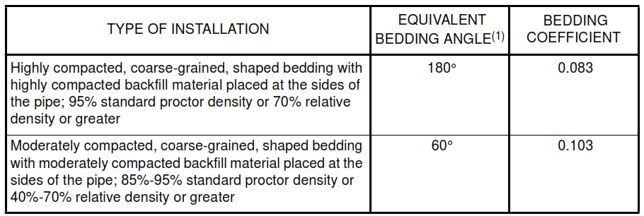
The bedding angle is an estimate of the degree of support provided by the soil at the bottom and
haunch area of the pipe. The equivalent bedding angle may be achieved without special bottom
shaping provided that the backfill is placed and compacted at the sides of the pipe in several lifts
below the springline. For small diameter pipe at least one compacted lift is required below the
springline.
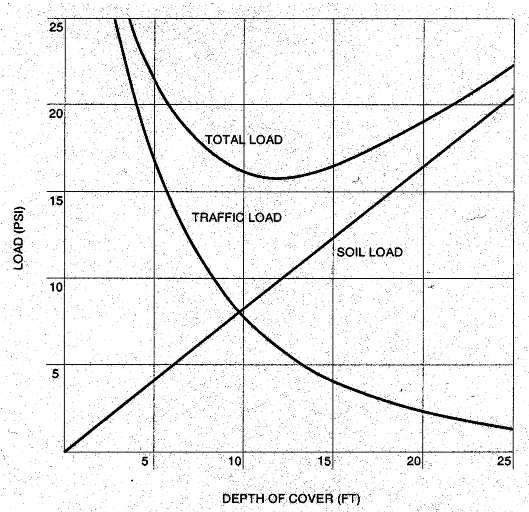
Note: The following charts are examples of the relationship between soil and live loads and their effect
on total load on the pipe.
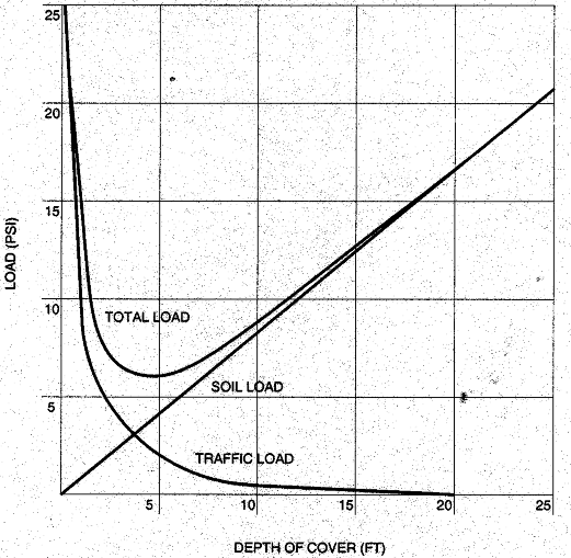
The chart above generally depicts standard highway loading, while the chart below is based on a
typical railroad loading. Charts are for demonstration purposes only and are not suitable for
determination of loads for use in design.
(ii) Hoop Stress / Strain
For design of underground pressure pipe, the components of stress from internal pressure and ring
bending shall be combined and compared to qualified hoop stress (HDS) in SES P01-E28-01.
Calculate the combined hoop stress:
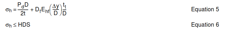
For underground pressure piping, in determining the axial allowable stress in 4.4, the combined hoop
stress (σh) above shall be used in the equation in SES P01-E28-01 as the hoop stress under applied
loads.
For design of gravity pipe where internal pressures are negligible, the strain from ring bending shall
be calculated and compared to the allowable ring bending strain in SES P01-E28-01.
Calculate the Ring Bending Strain:

Where:
σh = combined hoop stress
εb = ring bending strain
Pd = design pressure
D = pipe diameter
Ehf = hoop flexural (ring bending) modulus of elasticity
t = structural wall thickness
tt =
total wall thickness
Df = shape factor per M45
∆y = vertical deflection
HDS = hydrostatic design stress
In determining the axial allowable stress for non-pressure underground pipe, the value σ1 from
SES P01-E28-01 shall be used.
d. Buckling Resistance
Buckling resistance of underground pipe shall be calculated in accordance with AWWA M45, Section 5.7.5,
except as noted below. Pipe must be adequate to withstand the Design Vacuum in combination with the
peak external pressure resulting from burial loads and groundwater elevation.
External pressure due to groundwater shall be calculated based on the elevation of the maximum potential
groundwater elevation relative to the invert of the pipe.
e. Calculation of axial stress in Fixed Pipe Region
1. Minimum axial strength
All pipe and restrained joints in the underground piping system must have sufficient strength to carry the
most severe combination of loads resulting from temperature change, Poisson effect, and trench curvature.
The combined stress from these effects must not exceed the allowable stress determined in P01-E28-01.
Pipe near changes in direction or where settlement is expected will have additional axial bending stress.
Typically, the addition of bending stresses in local areas is offset by diminishing stresses from temperature
change and Poisson effect. Computer analysis is the only effective means of calculating combined axial
stress in these areas and will determine if pipe with increased axial capability is required.
Loads that produce axial tension in the pipe are of primary concern. Compressive stresses can usually be
ignored.
The use of bell and spigot joints, couplings, or other joints that allow axial motion shall not be considered to
relieve axial tensile stresses.
2. Axial stress from temperature change
Restrained thermal contraction produces axial tensile stress in the pipe. This condition exists whenever the
operating temperature of the fluid in the pipe is lower than the installation temperature of the pipe.

Calculate axial stress due to restrained thermal contraction:
σt = αEat(∆T)
Equation 8
Where:
σt = axial stress from restrained thermal contraction
α = axial coefficient of linear thermal expansion
Eat = axial tensile modulus of elasticity
∆T =
installation temperature minus minimum operating temperature
3. Axial stress from Poisson effect
Hoop expansion due to internal pressure tends to cause the pipe to contract in the axial direction. The
axial movement is prevented by soil friction and axial tensile stress is developed.
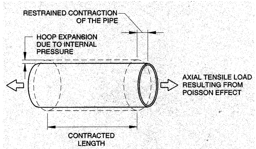
Calculate axial stress due to restrained Poisson effect:

Where:
σµ = axial stress from restrained Poisson effect
µha = Poisson ratio (axial response to an applied hoop load)
Pd = design pressure
R = radius of pipe
Eat = axial tensile modulus of elasticity
Eht = hoop tensile modulus of elasticity
t
= structural wall thickness
4. Axial stress from bending curvature
Beam bending inducing axial stress in the pipe can result from an uneven bedding, differential settlement
and subsidence of the soil. The pipe design shall allow for trench irregularities that cannot be resolved at
joints and for potential settlement and subsidence by applying an appropriate bending model to calculate
the resulting stress. The general equation based on a uniform radius of curvature of the pipe, as well as
one additional example are given below.
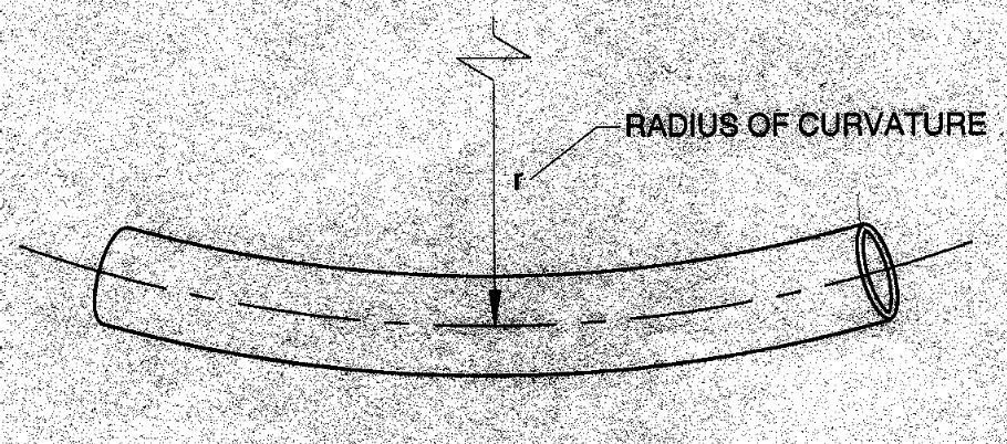
Calculate axial stress due to a uniform radius of curvature:

The following example is based on the assumption that the pipe is fixed on both ends, with displacement
forced at one end.
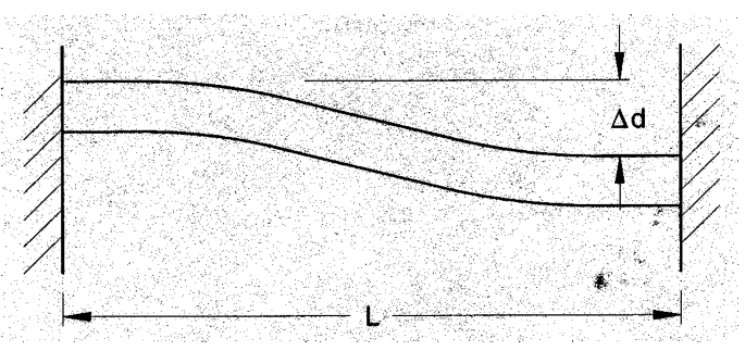

Where:
σc = axial stress from curvature
Eaf = axial flexural modulus of elasticity
R = radius of pipe
r
= radius of curvature of deflected pipe
M = bending moment from the selected beam bending model
∆d = expected displacement from trench irregularities or settlement
L = assumed length over which displacement occurs
It is the responsibility of the designer to select an appropriate beam bending model to represent the
anticipated displacement of the pipe in the specific system.
5. Combined axial stress in Fixed Pipe Regions
The allowable axial stress used for design is determined SES P01-E28-01 and shall be compared to the
combined axial stresses as follows:
σax > σt + σµ + σc
Equation 12
Where:
σax = allowable axial stress under combined loading conditions, per SES P01-E28-01
σt = axial stress from restrained thermal contraction
σµ = axial stress from restrained Poisson effect
σc = axial stress from curvature
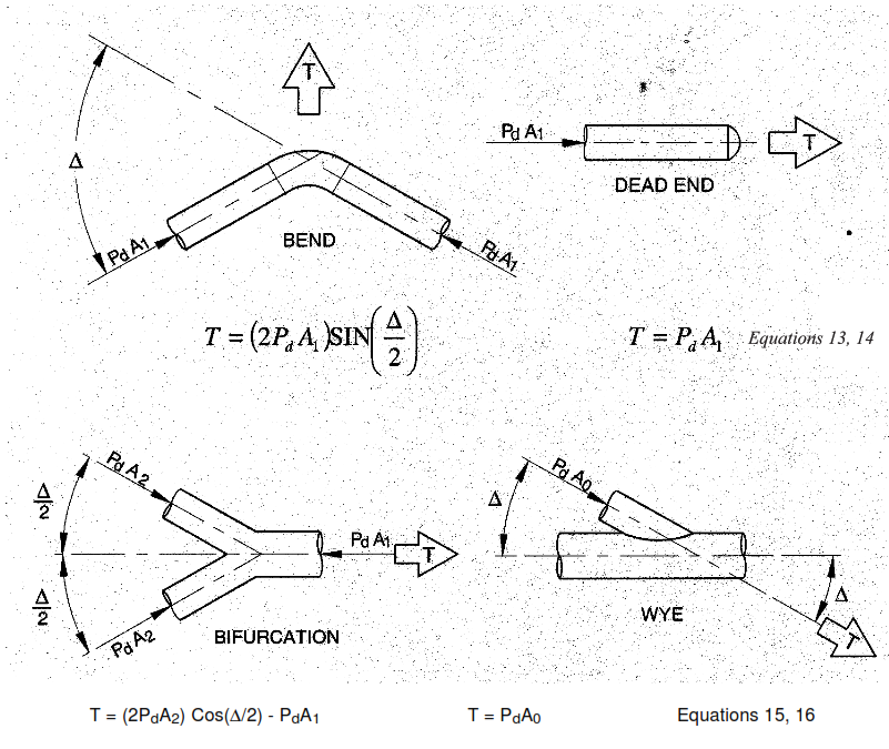
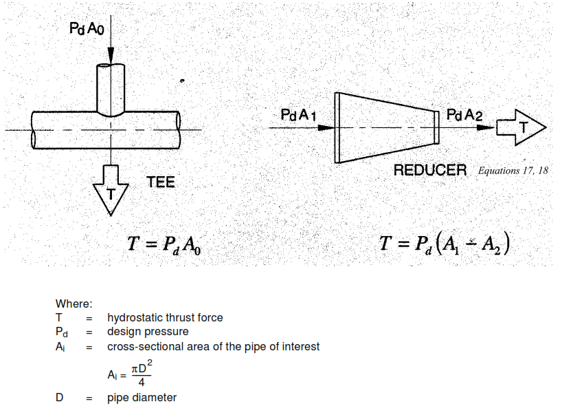
f. Thrust restraint
1. Thrust Forces
All thrust forces occur at changes in direction, changes in cross-sectional area, and at pipeline
terminations. Thrust forces develop as a result of the static internal pressure in the pipe and dynamic
thrust due to changes in momentum of a flowing fluid. Since pipelines generally operate at low fluid
velocities, dynamic forces are usually very small when compared to the static pressure force and can be
ignored. Forces from thermal expansion of the pipe are additive to thrust forces from internal pressure but
displacements are usually small as movement is resisted by pipe-soil friction. Thermal forces are usually
ignored when computing thrust forces.
Typical examples of hydrostatic thrust are shown in the following Figures. Calculate hydrostatic thrust
force T as noted below for the specific configuration:
2. Restrained (Tied) Joints
Thrust forces may be resisted by tying adjacent pipes to the fitting to increase the frictional drag of the
connected pipe. The thrust force diminishes from a maximum value at the fitting to zero some distance
from the fitting. At this location, the virtual anchor, friction forces are in equilibrium with thrust forces. Pipe
between the virtual anchor and the fitting is moving axially as the passive soil resistance against opposing
leg of the pipe and fitting is usually not sufficient to prevent movement. In order to generate the frictional
drag necessary to resist thrust forces, all joints within this moving length must be capable of transmitting
the axial forces.
To determine the length of pipe, the needed frictional resistance and the virtual anchor position, the
following procedures may be used:
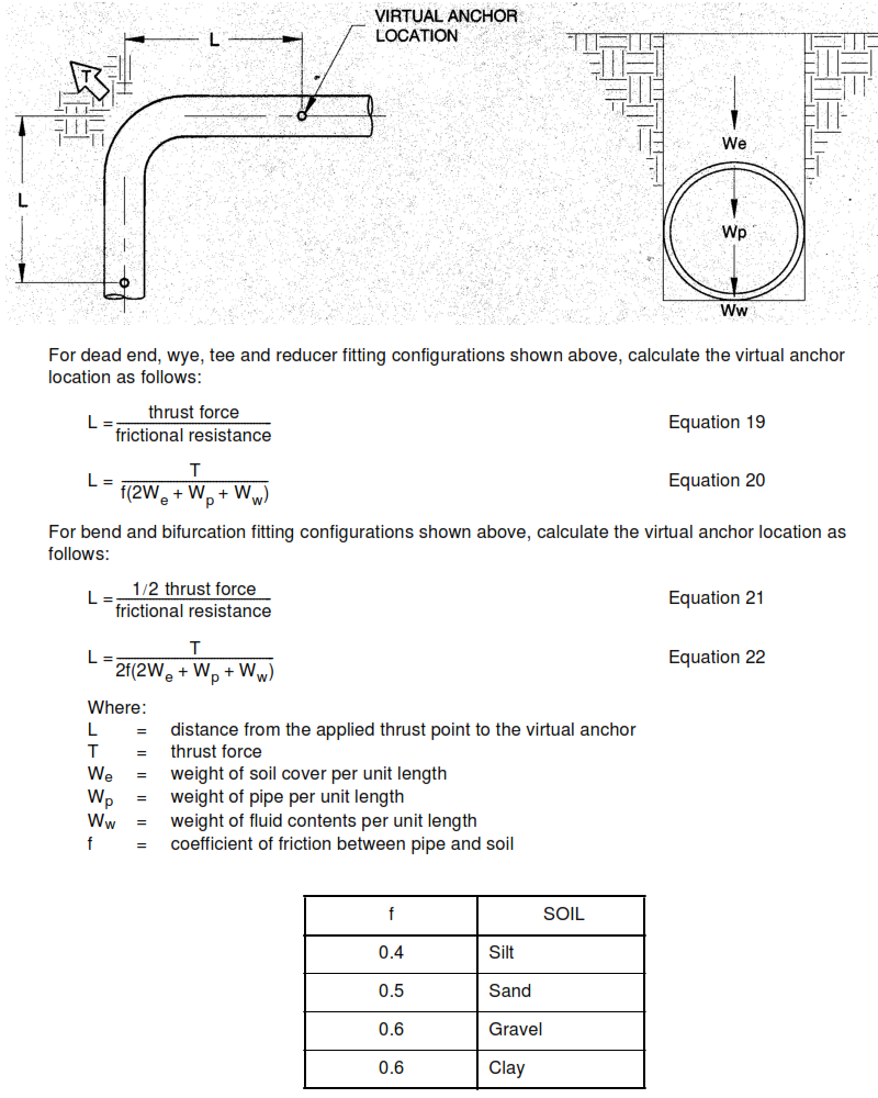
3. Horizontal Fittings
For horizontal fittings, the length of pipe to the virtual anchor location of any pipe leg is determined by
dividing the thrust force in that pipe leg by the frictional resistance per unit length. Depending on the
configuration of fitting and the pipe leg of interest, the thrust load varies.
The following Figure shows the configuration for a 90° bend. The two general equations for determining the
virtual anchor location for various types of fittings are also shown.
Note: These values are appropriate for soils compacted to 95% of the maximum dry density as determined
by the Standard Proctor method, ASTM D 698
4. Vertical Bends
Uplift forces caused by vertical bends shall be resisted by dead weight alone, without the benefit of
frictional forces. The mass of the length of pipe tied to each leg of the bend provides the necessary
balancing forces. Joints within this tied length must be capable of transmitting axial forces.
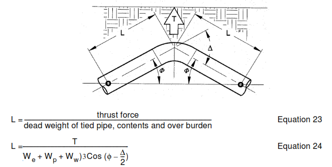
Where:
L =
tied length
T = thrust force
We = weight of soil cover per unit length
Wp = weight of pipe per unit length
Ww = weight of fluid contents per unit length
φ = angle of pipe per above Figure
∆ = angle of pipe per above Figure
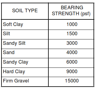
5. Thrust Blocks
Concrete thrust blocks increase the ability of fittings to resist movement by increasing the bearing area and
dead weight of the fitting.
Thrust blocks should be shaped with the ‘bearing area’ against undisturbed native soil of the trench wall
and perpendicular to the direction of the thrust.
The ‘bearing area’ of the thrust block is determined by:
Ab = TN / s Equation 25
Where:
Ab = bearing area of thrust block
T = thrust force
N = 1.5, minimum safety factor
s = bearing strength of soil
Knowledge of local native soil conditions is necessary for proper sizing of thrust blocks. The designer must
select the proper bearing strength of a particular soil type. Typical values for bearing strength are given in
the following table:
This procedure for sizing thrust blocks is typically valid when the depth to the bottom of the block is twice
the height of the block. For shallower thrust blocks shear resistance of the passive soil wedge behind the
block rather than bearing strength may govern. In this case special design consideration is required.
The dimensions of the thrust block should be large enough so that the pipe is encapsulated. At the
junction of the pipe and thrust block excessive bending stresses can develop between the pipe and rigid
concrete. The pipe should be wrapped in rubber at the interface to cushion the pipe and distribute
stresses.
g. Combined Axial Stress in Moving Pipe Regions
For pipe in moving regions near changes in direction, stresses from restrained temperature change and
Poisson effect decrease from maximum at the virtual anchor position to nearly zero at the fitting. However,
axial bending stresses resulting from movement into the soil reach maximum near the fitting. In many
installations the changing stresses in the moving pipe regions tend to be self-balancing and pipe designed
for fixed pipe regions is adequate. This tendency is heavily dependent on operating conditions and soil
parameters and for most applications, computer analysis should be used to accurately determine
combined axial stresses.
Generally, when thrust blocks are used or if all of the following criteria are met, computer analysis is not
required.
1. + temperature change < 20 °C, between installation temperature and operating temperature
2. operating pressure < 3.5 bar
3. compact granular native soil as defined in AWWA M45
4. granular backfill with compaction density > 90% Standard Proctor as defined in AWWA M45
5. Settlement of fitting or pipeline terminations is not expected or is otherwise relieved.
As a minimum, pipe in moving regions shall be designed for the same axial stresses as pipe in fixed
regions or for hydrostatic pressure thrust as defined below, whichever is greater.
Calculate pressure thrust:
Fp = PdAi
Equation 26
Calculate the axial stress due to pressure thrust:
σp = Pd R / 2t Equation 27
Where:
Fp = pressure thrust
σp = axial stress due to pressure thrust
Pd = design pressure
Ai = cross-sectional area of the pipe of interest
2
Ai = πD² / 4
R = average radius
t
= structural wall thickness
D = pipe diameter
The allowable axial stress used for design is determined in SES P01-E28-01 and shall be compared to the
axial stress due to pressure thrust as follows:
σa ≥ σp
Equation 28
Where:
σax = allowable axial stress under combined loading conditions, per SES P01-E28-01
σp = axial stress due to pressure thrust
5.2.4 Computer techniques
a. General
Many computer programs that model aboveground piping systems include an option for analysis of
underground piping systems. This analysis technique should be used in determining combined axial
stresses in the “moving pipe” regions where bending stresses are encountered and in areas where
settlement is anticipated.
Computer analysis is not intended to replace the traditional manual calculations in 5.2.3 of this standard.
Computer analysis should be used to augment manual calculations where the manual procedures do not
provide sufficient resolution.
b. Computer Analysis Requirements
Program requirements for computer analysis of underground piping systems are the same as those for
aboveground systems with the additional ability to model pipe-soil interaction.
The backfill and native soils provide resistance to movement of an underground pipe and the magnitude of
displacements is dependent upon the stiffness of this surrounding soil envelope. Because of this
dependency, it is critical that the soil properties input in the computer analysis accurately represent the
intended installation. The geotechnical factors required as input by computer programs includes:
6. Soil density
7. Coefficient of friction between pipe and soil
8. Friction angle between pipe and soil
9. Coefficient of horizontal stress (coefficient of horizontal subgrade reaction)
10. Undrained shear strength
From this simplified input many other geotechnical factors, soil stiffnesses and strengths, and ultimate
loads are computed to fully characterize pipe-soil interaction. The designer must have a thorough
understanding of how this input is used in internal program computations and of how pipe behavior and
axial stresses are affected. Since the geotechnical input is seldom available with a high degree of certainty
it is advisable to bound the analysis fixing the limits of potential soil properties.
The buried pipe will displace laterally in areas adjacent to bends and tees, and in areas far removed from
bends and tees, the displacement is primarily axial. Vertical displacements occur at vertical changes in
direction and where settlement is input directly. Properly modeled, the analysis will show fixed and moving
regions of pipe with maximum bending stresses at bends and tees, diminishing to zero at the virtual
anchor position.
The results of the computer analysis can be verified by manual calculations of the virtual anchor position
and combined axial stress in “fixed pipe” regions of the system in 5.2.3.e of this standard.
a. Combined Stresses
The stress analysis results should be compared to the appropriate sections of this standard as follows:
11. The hoop stress at maximum design pressure must be combined with hoop bending stresses
determined in 5.2.3.c and be less than the allowable hoop stress (HDS) or ring bending strain determined
in SES P01-E28-01 as appropriate.
12. The combined sum of axial bending and direct tension must be less than the allowable stress
determined in SES P01-E28-01.
6. Design Report Requirements
Contractor shall provide a complete report covering the design of the piping system in sufficient detail to
allow verification of all aspects of design, qualification and system analysis. The Design Report shall also
include additional data as required to support other project areas, including but not necessarily limited to
the information listed below.
6.1 Summary of Design Conditions and Assumptions
All project design conditions, service considerations, installation requirements, design assumptions and
other criteria used as a basis for the design and analysis of the piping shall be summarized for use by the
project and documented in the Design Report. The Design Condition Summary form included in
Appendix A or a similar format is preferred for quick reference, but additional explanation may be needed
for completeness.
The following general categories shall be included; refer to the applicable sections of this standard for
additional clarification:
6.1.1 Operating and Upset Design Conditions
Include the full range of positive and negative pressures and temperatures potentially experienced in the
system.
6.1.2 Wind and Earthquake Conditions.
6.1.3 Burial Conditions
Include any available information used as a basis for classification of native soils or other site conditions.
Include all underground pipe installation conditions to fully describe the excavation and backfill methods to
be used as a basis for the associated design parameters. Include manufacturer’s installation specification.
Include groundwater, surface conditions, anticipated settlement, or any other unusual sources of load on
the pipe.
Include the range of installation temperatures anticipated or used as the basis for the analysis.
6.1.4 Live Loads
Define all loads resulting from personnel, traffic, construction or other potential sources.
6.1.5 Service Considerations
Describe the service fluids and other special conditions which may affect material selection or
serviceability of the piping.
6.2 Qualification of Pipe and Components
All data developed by the pipe manufacturer as the basis for the qualification of the pipe and components
shall be included in the Design Report. As a minimum, this shall include the following:
6.2.1 Complete description of the construction of each of the components qualified, including but not
necessarily limited to the following:
a. All materials used, including resin, catalyst system, additives, reinforcement types.
b. Corrosion liner thickness and type.
c. Structural wall thickness, reinforcement types and sequence, glass orientation and glass content.
6.2.2 Complete description of the qualification processes used, with a listing of the components qualified
under each separate qualification process.
6.2.3 Description of the basis for materials selection, including data from materials manufacturers
supporting the use of the materials in the specific service.
6.2.4 For services considered more corrosive or abrasive than the testing medium, include verification of
the corrosion or abrasion resistance of the materials used and the basis for the use of any additional
corrosion liner thickness.
6.2.5 Include the basis used for adjustment to pipe pressure rating or properties, as required to
compensate for operational temperatures exceeding test temperatures.
6.2.6 Listing of all tests performed and used as a basis for the qualification, including:
a. Number and size of samples for each test.
b. Verification of construction of samples, compared to 6.2.1.
c. Dates of testing.
d. Description of test apparatus.
e. Complete presentation of data from tests.
f. Complete statistical analysis of data.
g. For standardized tests, the reporting requirements of the test procedure documents shall be satisfied in
addition to those listed above.
h. Summary of properties obtained from the testing required for use in the analysis, including development
of allowable stresses.
6.2.7 A listing of all construction data and test values, including minimum values and tolerances, as
required to provide a basis for quality control and verification that production pipe and components satisfy
the requirements of the qualification procedure.
6.2.8 Manufacturer’s recommended installation requirements.
6.3 Calculation Package
6.3.1 All manual calculations as required by this standard
6.3.2 For computer flexibility analysis or other computerized calculations, provide the following:
a. Program name and version.
b. All input data and basis for the data.
c. Program global settings and parameters.
d. Summary of all load cases and combinations considered, whether or not included in the analysis.
e. Model data in electronic form, if requested.
6.3.3 Code compliance report, if required by the project.
6.4 Drawings
6.4.1 Identify support types and locations, shear collar locations.
6.4.2 Location of any special requirements.
6.4.3 Fabrication details of any special requirements.
6.5 Data
6.5.1 Provide a method to correlate the analysis data to specific locations on the drawings and analysis
model.
6.5.2 Summary of maximum stresses and strains, compared to the appropriate allowable values.
6.5.3 Support Loads.
6.5.4 Loads on equipment nozzles
6.5.5 Displacements
APPENDIX A
Design Condition Summary