Following contents to be discussed in this article
- SCOPE
- REFERENCES
- GENERAL
- COATING PROCESSES
- Plasma,
- Jet-Kote
- Detonation (D-gun)
- Flame Spraying
- COATING MATERIALS AND APPLICATIONS
- General
- Typical metals and alloys
- Refractory oxides of metals
- Hardness values
- DESIGN CONSIDERATIONS
- General
- FINISHING
- General
- Metal coatings
- Oxide and carbide coatings
- APPROVAL OF VENDORS FOR APPLICATION OF THERMAL SPRAY COATINGS
FIGURE
- Plasma Spray
- Jet Kote Gun
- Detonation Gun (D-Gun)
- Flame Spray
TABLE
- Plasma Coating Properties
- Jet-Kote Coating Properties
- Detonation gun coating properties
- Flame spray coating properties
Thermal Spray Coatings Guide to Selection of Processes and Materials
1. Scope
This article provides characteristics and selection guide for Plasma, Detonation, Jet-Kote and Flame-Spraying Process. Thermal Spray Coatings are applied to enhance mechanical and for corrosion surface properties.
As an alternative, hard facing metals also can be deposited on workpieces using standard welding methods as described in SES W15-F01, which produce a metallurgical bond versus the mechanical bond of thermal spray processes.
2. References
Reference is made in this article to the following documents.
3. General
3.1 Thermal spraying is the application of a coating material to a workpiece, The material is partially or completely melted in an application gun, then propelled at high velocity by a gas to the workpiece where it mechanically bonds. These processes need not raise the temperature of the workpiece more than 300°F; therefore, they do not cause significant distortion or metallurgical changes.
3.2 Some uses of these coatings are:
a. Wear resistance
b. Corrosion resistance-galvanically, not as a barrier
c. Surface texture – (1) to smooth or roughen, (2) to anchor plastic coatings
d. Surface restoration or part rebuilding
e. Weight reduction (With lightweight substrate material)
f. Cost reduction (with low-cost substrate material)
g. Electrical and thermal insulation
3.3 Investment in spray equipment noise and contamination contaminant facilities and training needed to infrequently apply spray coatings is not justified. Many vendors are trained and equipped to satisfactorily apply coatings of this type.
4. Coating Processes
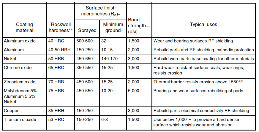
4.1 Plasma
This process uses a confined high-current electric arc and an inert gas such as argon to produce a high -pressure stream of hot ionized gas called plasma. In operation, as shown in Figure 1 the gas is directed through the nozzle and an arc is struck between the electrode and the nozzle. In passing through the arc the gas is ionized and forms a stream of plasma with temperatures as high as 30,000°F.
Powder fed into the plasma stream melts and is propelled to the workpiece at approximately 400 feet per second. Coatings applied by this method are more dense and more costly then those applied by flame spraying. Bonding to the workpiece is mechanical with strengths varying between 430 and 10.000 pis with porosity of 5 percent or less Thickness of applied coatings can be from 0.002 in. to over 0.100 in. and depends upon the material sprayed and shape of the workpiece.
Figure 1. Plasma Spray

4.2 Jet-Kote
The combustion chamber of a Jet-Kote hypervelocity gun continuously burns gaseous fuels [propane, propylene, methylacetylenepropadiene (MAP), or hydrogen] in oxygen. Fuel gas pressure can be varied from 60 psi to 90 psi which controls deposit density and hardness by its effect on velocity. Hot gases from the combustion chamber, as shown in Figure 2, feed into a nozzle to melt metal powder injected into the center of the gas stream. Slightly fuel rich, the gases protect and propel droplets from the nozzle to the workpiece at supersonic speed – typically around 300 ft/s. This process is continuous and competitive, hence is closer in coating cost to plasma then to the detonation gun process. The coating bond strength is between that of plasma and the detonation gun.
Deposit hardness and density (porosity content) can be made to equal or slightly exceed that of the detonation gun process. Coating thicknesses for this process range from 0.002 in. to 0.100 in. depending upon the application.
Figure 2. Jet Kote Gun

4.3 Detonation (D-gun)
In this process, acetylene, oxygen, and the powder to be sprayed are fed to one end of a long barrel-type torch, as shown in Figure 3. Ignition of the gas is by spark plug firing at 8 times per second.The resulting explosions heat and accelerate the powders down the barrel and on to the workpiece at speed of 2,500 feet per second the powders impact on the surface in a molten or semimolten state and achieve bond strengths of up to 25,000 psi with approximately 0.5 percent porosity. Coatings applied by this process are considered the standard by which others are judged. Thickness of applied coating can be form 0.002 in. to 0.010 in. and depends upon the material sprayed and shape of workpiece.
Figure 3. Detonation Gun (D-Gun)
")
4.4 Flame Spraying
This method is generally the least costly of the four spraying processes described in this standard. As shown in Figure 4, coating materials in the form of powder, wire, or rod are fed to a torch fueled by a gas such as acetylene. Combustion with air or oxygen heats, melts, and propels the material to the workpiece at approximately 300 feet per second. Flame temperatures are approximately 6,000°F and bonding to the workpiece is mechanical. Thickness of applied coatings can be from 0.002 in to over 0.100 in. depending upon the material sprayed and shape of the wood piece. Bond strength can vary between 600 and 1,000 psi and porosity vary between 10 and 20 percent. In a variation of flame spraying, a thin coating is sprayed upon the work-piece and subsequently fused in place by a secondary heat application.
Figure 4. Flame Spray

5. Coating Materials and Applications
5.1 General
Materials that do not decompose, vaporize, or separate on heating can be thermal sprayed. Refer to Tables 1, 2,3 and 4 for selection of processes and Materials.
5.2 Typical Metals and Alloys
Typical metals and alloys that can be sprayed are zinc, titanium, tungsten, nickel, chromium, tantalum, aluminum, zirconium, iridium, nichrome, stainless steel, babbitt, and bronze. Generally, metals are used to repair and build up worn parts such as bearing shafts. Nickel, titanium, and molybdenum are used as undercoats to obtain better bond strengths for subsequent ceramic coatings. Zinc and aluminum are applied for cathodic corrosion protection. Spray coatings are too porous to provide barrier corrosion protection.
A binder such as cobalt or nickel proportionally mixed with coating material for wear and abrasion resistance where mechanical shock is involved. Knife blades, sliding valves, saw teeth, and piston rods are typical parts coated.
5.3 Refractory Oxides Of Metals
Such as aluminum, chromium, titanium, and zirconium are used for wear resistance. Chromium oxide has a low coefficient of friction. Zirconium oxide has good heat and thermal shock resistance and is used for high-temperature work. Aluminum oxide is a low cost general-purpose coating.
5.4 Hardness Values
Hardness values of the coated materials in the tables are from manufacturers’ data and are relative values to use in design selection.Hardness and other physical properties vary due to vaporization, oxidation and contamination during application. Coatings are usually thin and deflect into substrate during hardness testing and therefore require special hardness tests such as Vickers which are available at the Engineering Test Center.
6. Design Considerations
6.1 General
Thermal sprayed coatings do not have the same properties as the identical bulk materials. Passage of the coating particles through the flame or arc causes preferential vaporization and oxidation. Particles from an over heated nozzle can contaminate the coating. Coating variables such as structure and porosity affect both strength and modulus. Oxide coatings usually exhibit extremely large deviations in bond strength, therefore de-signers must specify a bond strength for each design (see tables for guidance). Workpiece surfaces must be prepared carefully to ensure proper bonding of the coating. Metal undercoats frequently are recommended for some plasma and flame-spray processes to improve bond strength. How ever, self-bonding one-step powder coatings are available which eliminate this additional step. Coatings can only be applied to workpieces with hardness less than 50 HRC.
6.2 Several further design considerations pertain to sprayed coating thickness. Adherence of the coating is much superior at the minimum thickness end of the range. As the coating thickness increases, adhesion decreased to the point where spalling becomes a major concern. On textile rolls and other applications where periodic respraying is necessary, a word of caution is in order when successive undercutting may weaken the roll and affect its stability.
7. Finishing
7.1 General
The “as deposited” thermal-spray coatings have a wide range of roughness and some type of finishing operation usually is required. This operation is normally performed by the coating vendor.
7.2 Metal Coatings
Metal coatings can be finished using standard grinding and polishing procedures common to the metal working field. In cutting coated material, cutter rotation must be such that the coating is pushed down against the substrate.
7.3 Oxide and Carbide Coatings
Oxide and carbide coatings, because of their hardness, required diamond tooling for precision finishing and silicon carbide for other noncritical finishing. These coatings are also sensitive to cutter rotation direction.
8. Approval of Vendors for Application of Thermal Spray Coatings
8.1 Substrate preparation, cleanliness, spray materials, and spray technique determine the quality of the coating and its adherence to the sub-strate. It is difficult to nondestructively judge coating quality and adherence after application. Therefore, it is important that vendors with substantial histories of good reputation be utilized since their higher prices reflect better preparation, materials, and techniques.
TABLE I – Plasma Coating Properties*
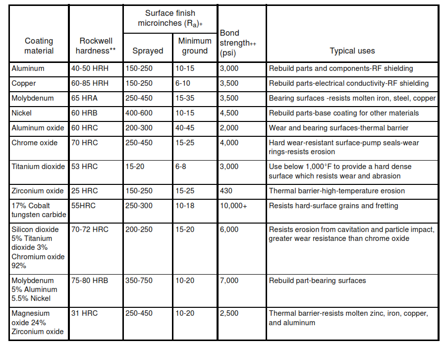
TABLE II -Jet-Kote Coating Properties
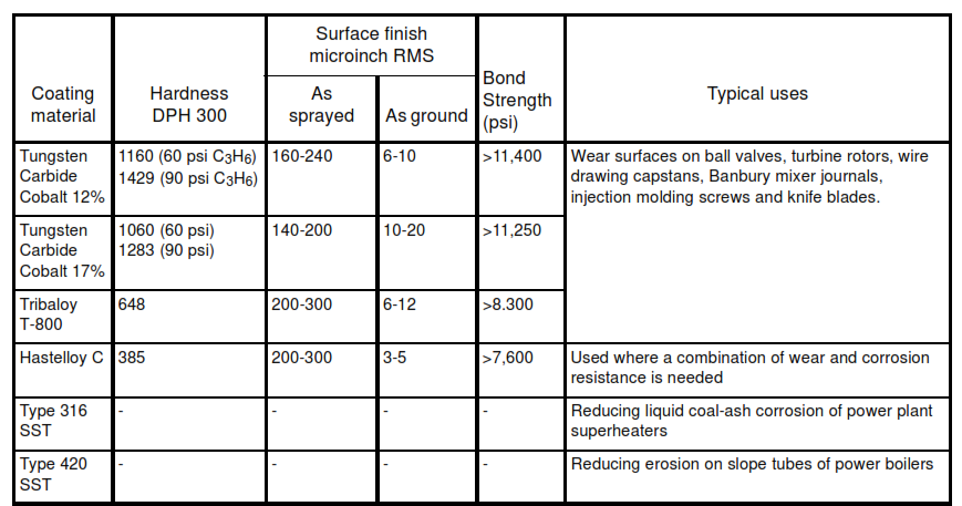
TABLE III – Detonation gun coating properties*
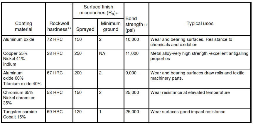
TABLE IV -Flame spray coating properties