This article is about underground installation requirements, under ground duct bank design requirements as per NEC, underground Trenches, Cable installed in Concrete Trenches as per NEC and International code and standards.

Electrical Underground System Applications.
- Underground installations of electrical conduit, cable, conductors or duct bank systems must be approved by company.
- The following underground installation types are acceptable.
- a. Direct buried cable.
- b. Direct buried conduit.
- c. Duct bank (concrete encased conduit).
- d. Cable in concrete trenches.
- Direct buried cable or conduit shall be installed in prepared trenches as defined in this technical specification. Plowing of cable or conduit directly into the earth is not permitted.
- Conduit and/or cable for direct burial shall be selected per the requirements of this document.
- Duct banks shall be constructed with the use of concrete forms or by the use of precast duct banks.
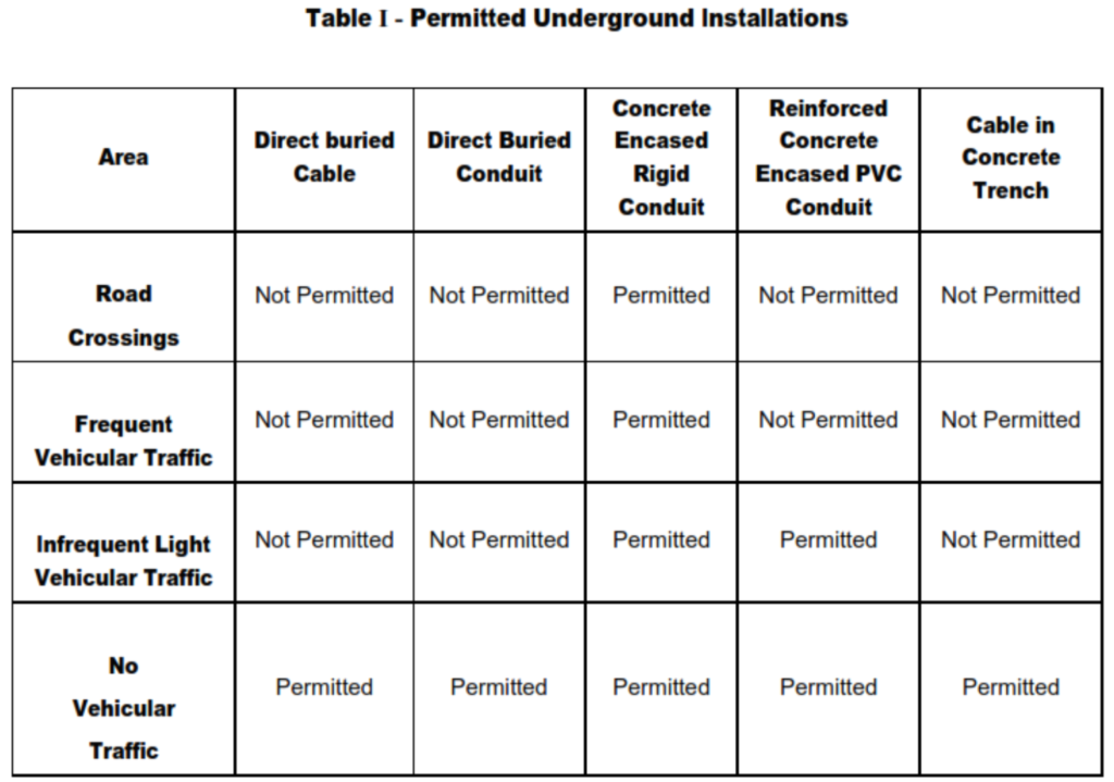
- Conduit material (RGS or PVC) for use in duct bank applications shall be selected per the requirements of this document. Refer to Table 1 for permitted U.G. installations.
Underground Installation Requirements.
Underground Routing.
a. The location of all underground runs shall be selected with consideration for future structural installations in the area.
b. In general, underground conduits and duct banks shall be installed below sewer lines and other piping.
c. Do not install any portion of the duct bank in the 45° cone of deflection from the low point of foundations.
d. The top of the concrete envelope shall be located a minimum of 610 mm (24 inches) below grade. Where the conduit stubs up, the concrete envelope shall extend at least 150 mm (6 inches) above grade and shall be sloped.
e. In general, the depth of a conduit duct bank shall be established by the bending radius of the largest conduit in the duct bank. The minimum bending radius shall be 10 times the conduit diameter.
f. Conduit that runs under building slabs or roadways shall extend 1.5 meters beyond the building slab or edge of road.
g. General Conduit Requirements.
a. Rigid metal conduit shall be used for underground installations whenever an extra high-strength installation is required such as in equipment foundations.
b. All direct buried conduit shall be rigid hot dipped galvanized steel.
c. Unless marked for a higher temperature, nonmetallic (plastic) conduit (Schedule 40 and Schedule 80) is intended for use with wires rated 75°C or less.
d. When encased in concrete in trenches outside of buildings, it is suitable for use with wires rated 90°C or less.
e. Direct-buried conduit is suitable for cables rated over 600 volts when it is buried to a depth in accordance with Table 1 in Direct Buried Cable Installation Trench Requirements.
f. For separation of control, instrument and communication circuits, refer to article.
g. To facilitate maintenance, an adequate horizontal and vertical separation shall be provided between underground conduits or duct banks and foreign structures, such as water mains, sewers and gas lines. A minimum separation of 305 mm (12 in) shall be maintained where possible.
h. 34.5 kV and 13.8 kV cables shall be installed in one or two horizontal layers with separation as determined by ampacity derating studies and as required for future access for repair.
i. All underground conduits shall be concrete encased unless approved otherwise by the company.
Underground Duct Bank Design Requirements.
- Duct banks shall be constructed of either hot dipped galvanized rigid steel conduit encased in concrete or PVC conduit encased in reinforced concrete.
- Spacers to provide a minimum separation between conduits of 1 inch (25mm) for conduits 1.5 inches (38mm) or smaller and 2 inches (51mm) for conduits of 2 inches (51mm) or larger. The spacers shall be placed at intervals of approximately 8 ft.
- Conduit runs in duct banks shall be made continuous by the use of couplings.
- Duct banks shall be provided with a minimum of 20 percent spare conduits of each size required.
- In duct banks constructed with rigid steel conduit, unreinforced non-structural concrete may be used.
- Concrete encasement shall extend a minimum of 76mm (3 inches) from any conduit in the bank to the outside surface.
- The top layer of concrete on the duct bank shall be red concrete. From grade to the top of duct bank shall be a minimum of 610 mm (24 inches).
- Conduit stub ups shall be rigid steel. Where PVC conduit is used, a transition to rigid steel conduit shall be made below grade using rigid steel bends.
- Manholes or handholes required for the duct bank system shall be located in non-hazardous classified areas. Manholes shall be provided with cable pulling irons embedded in the concrete side walls of the duct bank.
- Below grade duct bank locations shall be indicated by red concrete warning markers placed at 50m (164 ft.) intervals along the banks and at bends where no manhole is present.
General Requirements for Concrete encased Conduit.
- a. Minimum size of conduit for underground installation shall be 25mm (1 inch). Conduits 38mm (1 1/2inch) and smaller shall be rigid steel.
- b. Conduits 51mm (2 inch) and larger may be rigid nonmetallic PVC conduit.
Specific requirements for concrete encased Rigid Galvanized Steel (RGS) conduit.
a. RGS conduit in duct banks shall be installed, generally, as defined in Paragraph below.
b. The minimum size of RGS conduit shall be 1 inch (25mm).
c. When the U/G System includes manholes the conduit will pitch to a drain point in the manhole or junction box with drain.
d. If it is necessary to change directions with a group of conduit in a duct bank, the bends should be formed with the concentric system to maintain cross-section placement. The bends shall be long sweep configuration with 1.067m (42 inch) radius as a minimum.
e. All stub-outs, both vertical and horizontal, from the duct bank shall be installed with RGS conduit, including the elbows. PVC to RGS adapters shall be used when transitioning between types of conduit.
f. Conduit stub-outs in manholes or pull boxes shall be fitted with grounding bushings. Grounding jumper cable shall be installed from the grounding bushings on the entrance wall to the grounding bushings on the outlet wall to insure conduit continuity.
g. All underground conduits shall be concrete encased unless approved otherwise by the company.
Specific requirements for concrete encased PVC Conduit.
a. The minimum size of PVC conduit shall be 2 inch (51mm), schedule 40.
b. PVC connections shall be made using “welded”/glued socket type connector.
c. The PVC conduit shall be individually tied to their support and additionally tied to the reinforcing steel for the duct bank to prevent conduit float during concrete pour.
d. Non metallic conduit runs shall have rigid galvanized steel conduit elbows at stub-ups and for all 90° bends.
Duct Bank Layout as Per NEC.
a. Duct bank configurations shall contain sufficient conduits required for the present installation, 20% spare conduits required for probable future use and supernumerary conduits. Supernumerary conduits are those required for completing a layer of a standard duct configuration.
b. Consideration shall be given to a duct configuration that provides effective heat transfer where the duct bank contains power cables for mains and major feeders.
c. Consideration shall be given to the duct configurations and entry locations that provide the best racking conditions at manholes.
d. The minimum separation maintained between outside surfaces of conduits in duct banks shall be 38 mm (1.5 in) for conduits with diameters of 2 inches or less and 51 mm (2 in) for conduits greater than 51 mm (2 in) in diameter as shown in assembly drawings.
e. A green insulated, tin-plated copper 70 mm2 (2/0 AWG)minimum ground wire shall be installed within the duct bank and shall be connected to the ground grid at each end.
f. Cable pulling calculations shall be done on all underground duct banks to insure cables will not be damaged during installation.
Manhole Requirements.
a. The maximum straight run spacing of manholes shall be based on the maximum cable pull length for minimum cable size installed in the duct bank based on pulling calculations for the cables.
b. Manholes shall have a minimum inside dimensions of 2500 mm (98inches) square by 2000 mm (79-inches) deep.
c. Adequate space shall be allowed for: making splices; supporting splices, supporting cables; clearance between low voltage control, power and medium voltage cables; bending and training cables for offsets and changes in horizontal and vertical direction; providing adequate working clearance as required per NEC Article 210, for pulling, terminating and splicing cables.
d. Manholes shall be provided with a minimum of one (1) 760 mm (30-inch) manway cast into the top cover.
e. Accessories – Manholes shall be provided with the following accessories:
(i) A 250 mm (10-inch) square by 305 mm (12-inch) deep sump located in one corner of the manhole. A cover grating shall be required if the sump is located in a working area. The floor shall be sloped to the sump.
(ii) Pulling iron and cable racks.
(iii) Access ladders.
- Above Ground Splice Pull box requirements.
a. For all conduits feeding an A/G box, the first fitting above grade will be a seal fitting when any portion of the conduit run is through (or below) a hazardous area.
Handhole Requirements.
a. Where access is required for pulling cables, a shallower form of manhole, known as a handhole, may suffice where smaller chambers than those usually associated with manholes will provide sufficient and suitable space for cables and any associated equipment to be installed therein.
b. Handhole design and construction is similar to that for manhole construction as covered article manhole for construction details and guidelines.
c. No handholds should be installed in roadways or other areas which are subject to vehicular traffic. This requirement is a safety measure intended to protect workmen.
d. Frames and covers for handholes (service pits, boxes, etc) should provide the maximum working space for the personnel with the covers large enough to permit working from above the opening. Metallic covers and frames which form the entire roof of the handhole should be used.
e. Metallic covers and frames which form the handhole roof must be grounded in accordance with NEC Article 250 when enclosed circuits exceed 150 volts.
f. Precast concrete-type construction is allowable for handholes. They may be cast as one unit, or consist of a separate pipe or caisson with poured in-place concrete floor.
g. Poured-in-place concrete walls and bottoms for handholes up to 914mm (3 ft) in depth shall be 102 mm (4-in.) thick, reinforced with No. 3 bars at 304 mm (12 inch) center-to-center spacing each way. For handholes from 3 ft (914 mm) to 1828 mm (6 ft) in depth, concrete wall and bottom thickness shall be 152 mm (6 in.) and reinforced with No. 3 bars at 203 mm (8 in.) center-to-center spacing each way. All reinforcing is placed on center of walls and center of bottom slab.
Concrete
a. The concrete envelope surrounding the structure of rigid conduits shall have a minimum thickness of 76 mm (3 in) on the top, bottom and sides.
b. Where reinforced duct sections are required, the thickness of the concrete envelope shall be increased accordingly and reinforcing bar added.
c. The concrete shall be red, pigmented containing a minimum of 6 kg of red oxide per cubic yard. Concrete mixture shall have pea gravel aggregate not exceeding 19mm (¾ inch) in size.
Direct Buried Conduit.
General requirements of Non-Concrete Encased/Direct Buried Rigid Metal Conduit.
a. Generally the installation of below grade direct buried conduit should be avoided, except in buildings where conduit may be installed in concrete floors.
b. Below grade conduit shall be rigid hot dipped galvanized steel with a 40 mil (1.02 mm) PVC coating on the exterior surface and an epoxy coating on the interior surface.
c. Minimum size for below grade conduit shall be 25mm (1 inch). Below grade conduits shall be sized one size larger than required by NEC maximum wire fill.
e. Reductions in conduit size shall be done above grade.
f. Below grade bends shall be of the large radius type.
g. Minimum depth for conduit installations shall be per Table 1 in this article.
h. Below grade direct buried conduits shall have red tiles or red concrete cover.
i. Spare conduits shall be provided with pull cords, terminated with plugged couplings and installed flush with the finished floor in buildings or 25mm (1inch) above the finished surface in other areas.
Direct Buried Cable Installation.
Underground Trenches.
a. Cables suitable for direct burial outdoors in underground trenches shall be metal clad with an overall PVC jacket and listed for direct burial application.
b. Cables routed under buildings and stubbing up into electrical equipment shall be installed in conduit sleeves extending 1.5 m (60 inches) beyond building exterior buried edge of concrete foundation.
c. Cables passing through walls or other masonry structures shall be protected by conduit sleeves. These sleeves shall be packed and sealed after cable installation.
d. Below grade cable trenches should generally have earth side walls and bottoms unless otherwise noted.
e. Trenches shall be provided with space for 20 percent future cable additions. The future space shall be allocated in the top tier in trenches and conduit routed under roadways.
Cable installed in Concrete Trenches.
a. Cable trenches shall have load-bearing concrete sidewalls, concrete or metal covers, and an earth bottom. Bottom cross-members shall be installed at sufficient intervals to brace the trench walls. Trenches shall be designed to withstand the maximum loading established for the area in which they are to be installed.
b. Trench covers shall be removable, fitted with a means of attachment for a lifting device.
c. Trench covers shall be supported by the concrete trench sidewalls, the tops of the trench covers shall be flush with the adjacent paving.
Trench Configuration for Low Voltage Cables.
a. The bottom tier of cables in trenches shall be installed on a 75 mm (3in.) minimum layer of sand or selected screened fill material. For tiered power cable trenches a 150 mm (6in.)minimum layer of fill shall be provided between cable tiers. The top tier of cables shall be 200 mm (8in.) below the bottom of the protective red concrete covering slab. The space between the top tier of cable and the protective covering slab shall be completely filled with sand or selected screened fill. The maximum thermal resistivity of the fill sand for power cables shall be 120°C·cm/w.
b. The red concrete slabs installed over the cables shall be a minimum of 50 mm thick and fitted with lifting eyes. These protective slabs shall be laid end to end across the length of the trench at a depth of 360 mm (14 inches.) from finished grade.
c. After the red concrete slabs have been set in place across the trench, it shall be back filled within 150 mm (6 inches) of grade native soil to the level of finished grade.
d. Yellow warning tape with black letters (in Arabic and English) shall be provided 150mm above the red concrete slabs.
e. Trench location shall be indicated by red concrete warning markers placed at 30 m (100 ft.) intervals along the trench and at changes of direction.
f. Where trenches have concrete side walls, the top tier of cables shall be a minimum of 150 mm below the bottom of the trench cover. This space shall be completely filled with sand or selected screened fill.
g. In common trenches, low voltage branch circuits may be installed in up to a maximum 3 tier trench. Horizontal separation between cables shall be a minimum of 100 mm. Motor control cables shall be located in trenches with their associated power cables.
h. Thermal sand is not required for fill in trenches with only instrument and/or control cables or portions of trenches with only those cables.
GOOD EXPLANATION