The Dielectric Discharge test (DD) is a relatively recent method developed by EdF (Électricité de France), the national power utility of France, after extensive research. Unlike traditional insulation resistance tests that measure currents during the charging process, the DD test evaluates the current that flows when the test sample discharges. While it’s not a pure insulation resistance test, it provides valuable insights as an adjunct to traditional insulation tests.
Understanding the Dielectric Discharge Test:
Objective of the Test:
- Identifying Increased Aging: Electrical insulation in high-voltage equipment is designed to withstand various stresses for decades. However, abnormal stresses, like moisture or contamination, can accelerate the natural aging process of insulation. The Dielectric Discharge test aims to identify if this increased aging is occurring.
- Determining the Cause: If signs of increased aging are detected, the test helps pinpoint the underlying cause, such as moisture ingress, contamination, or other issues affecting the insulation.
- Prescribing Corrective Actions: Based on the test results and the identified cause, maintenance professionals can recommend appropriate actions to rectify the situation. This could include drying, cleaning, or even replacement of the insulation.
Spot Test vs. Diagnostic Testing:
- A standard “spot test” typically involves applying a voltage to insulation and measuring the resulting resistance. It provides basic information, such as whether the insulation is “good” or “bad.” However, it doesn’t offer insights into the cause of any issues or what actions should be taken.
- Diagnostic insulation testing, like the Dielectric Discharge test, goes beyond a simple pass/fail result. It provides a more comprehensive assessment of the insulation’s condition, helps identify the cause of problems, and suggests appropriate remedies.
Components of Test Current:
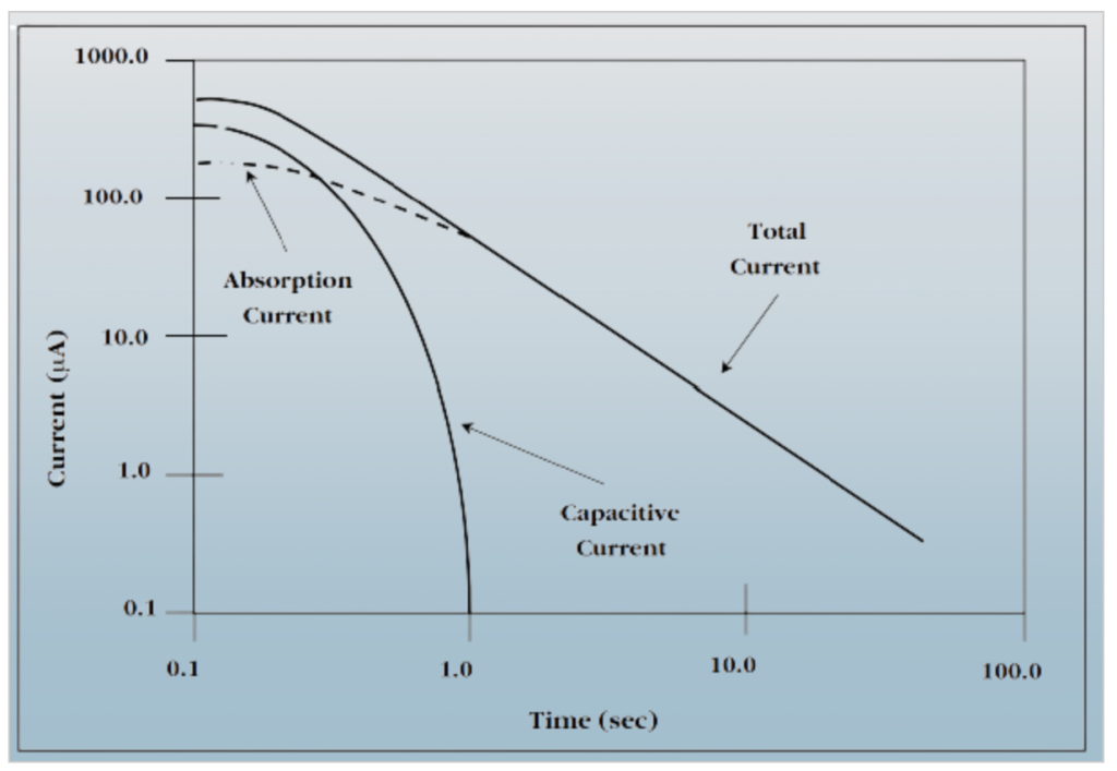
- During an insulation test, various currents flow, making the analysis more complex. These currents include:
- Capacitive Charging Current: This current initially surges as it charges the insulation’s capacitance but drops to near zero quickly.
- Absorption or Polarization Current: It has up to three components and decays more slowly over several minutes. It’s associated with the realignment of molecules and polarization effects in the insulation.
- Surface Leakage Current: This constant current is caused by moisture or contaminants on the insulation’s surface and depends on temperature.
- Conduction Current: It flows steadily through the insulation and is represented as a high-value resistor in parallel with capacitance.
Dielectric Discharge Test Process:
The Dielectric Discharge test involves a specific sequence of charging and discharging the insulation to assess its condition accurately. Here’s a detailed breakdown of this process:
1. Charging the Insulation:
- The test item, which contains the insulation being evaluated, is subjected to a high voltage for a specific duration, typically ranging from 10 to 30 minutes. Some advanced Megger insulation testers automate this test and charge the insulation for a standardized 30-minute duration.
- During this charging phase, the insulation’s capacitance becomes fully charged. Capacitance refers to the ability of the insulation to store an electrical charge.
2. Full Absorption:
- As the insulation is charged, it undergoes a process called “absorption.” This phase involves the realignment of molecules and polarization effects within the insulation.
- The absorption process continues until it reaches its peak or is essentially complete. This means that the insulation has absorbed as much electrical energy as it can during this time.
3. Leakage Current:
- While the absorption process is ongoing, the only current that continues to flow through the insulation is the “leakage current.” Leakage current typically persists as long as the insulation is under the influence of the high voltage.
4. Removing the Test Voltage:
- After the absorption phase is complete and the insulation is fully charged, the high test voltage is removed. This step marks the transition from the charging phase to the discharging phase of the test.
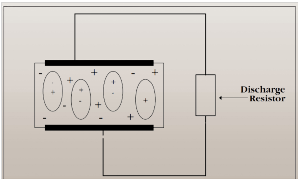
5. Discharging the Capacitive Charge:
- To rapidly discharge the capacitance stored in the insulation, the insulation tester activates its internal discharge resistors. These resistors provide a low-impedance path for the stored electrical energy in the insulation to dissipate.
- This quick discharge process ensures that the voltage across the insulation collapses rapidly.
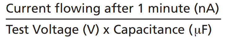
6. Measuring Remaining Current:
- After 60 seconds of discharging the capacitance, the insulation tester measures the current that continues to flow through the insulation.
- This measured current reflects the remaining effects of absorption (reabsorption) and any other leakage currents. By analyzing this current, valuable information about the insulation’s condition can be obtained.
The Dielectric Discharge test is particularly useful because it isolates the reabsorption current, allowing for a more accurate assessment of the insulation’s polarization and moisture content. This test method provides insights into the long-term behavior of the insulation and its ability to maintain electrical integrity.
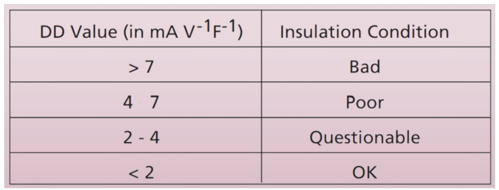
Interpreting DD Value:
- The Dielectric Discharge test results in a calculated index value. A low DD value indicates that reabsorption current is decaying quickly, suggesting that all layers of insulation have similar time constants. A high DD value implies that reabsorption exhibits long relaxation times, which may indicate issues in specific layers.
Layered Insulation:
- In high-voltage equipment, insulation often comprises multiple layers, each with its capacitance and leakage resistance. During the DD test, equal voltage stress is expected across these layers. Any discrepancies in the rate of decay of reabsorption current can reveal faults in specific layers.
Practical Application:
- The Dielectric Discharge test was initially developed for high-voltage generators but is applicable to any multi-layered insulation systems. It provides valuable insights into insulation conditions, particularly in complex layered setups where traditional tests might not reveal underlying issues.
In summary, the Dielectric Discharge test is a powerful diagnostic tool for assessing the condition of insulation in high-voltage equipment. It not only identifies issues but also helps determine their causes and recommends appropriate actions for maintenance and reliability. This method enhances the reliability and safety of critical electrical systems, preventing unexpected failures and downtime.
Related Articles:
What is Good insulation?
What Makes Insulation Go Bad?
How Insulation Resistance is Measured.
How to Interpret Resistance Readings.
Factors Affecting Insulation Resistance Readings.
Types of Insulation Resistance Tests.
Test Voltage vs. Equipment Rating.
AC Testing vs. DC.
Use of DC Dielectric Test Set.
Tests During Drying out of Equipment.
Effect of Temperature on insulation Resistance.
Effects of humidity.
Preparation of Apparatus to test.
Safety Precautions.
Connections for testing insulation resistance of electrical equipment.
Additional Notes About using A Megger Insulation Tester.
Interpretation-Minimum Values.
Minimum Values for Insulation Resistance.
Tests Using Multi-Voltage Megger Insulation Testers.
Step-Voltage Method.
Use of a Guard Terminal.