When classifying pumps used in smaller water systems, we generally place them into two predominant categories: dynamic pumps and displacement (or positive displacement) pumps. Each type has distinctive operational characteristics and applications, particularly reacting differently to alterations in discharge pressure.
Dynamic pumps are particularly suited to conditions where the necessity is for high volumes, and where alterations in flow don’t pose significant problems. These pumps exhibit a varying flow, meaning, when the discharge pressure is increased, the quantity of water pumped is subsequently decreased. A commonly recognized example of a dynamic pump is the centrifugal pump, which is extensively employed in various water systems due to its capability to manage high flow rates. Despite their versatility, dynamic pumps do experience fluctuations in pressure and flow, and their operation with a closed discharge valve can be sustained for only short durations to prevent damage, as pressure within the pump can escalate rapidly.
Conversely, displacement pumps, also termed positive displacement pumps, are integral where the need is for relatively small but exact volumes. These pumps have a capability to maintain a constant volume, indicating that variations in discharge pressure don’t alter the volume of water pumped. This consistent performance makes displacement pumps highly efficient and crucial in applications like chemical dosing, where precision is paramount. Diaphragm pumps, common types of displacement pumps, are frequently used to pump solutions of chlorine and fluoride due to their precision and reliability. However, the operation of displacement pumps with closed discharge valves is highly detrimental, and it’s imperative to avoid such operational conditions as the constant volume characteristic can lead to excessive pressure build-up, causing damage to pump components.

Centrifugal Pump is one of famous dynamic pumps.
Centrifugal Pumps:
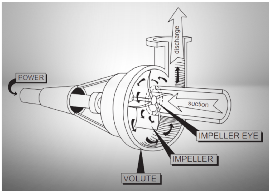
So, a pump is like a tool that gives energy to water, making it move faster or with more pressure.
Imagine you cut a hole in a pipe and use a paddle to stir the water; this is a simple form of a pump; you’re giving energy to the water. If you change the paddle to a more efficient shape, like an impeller, you can put more energy into the water, making it move faster. But, because of the spinning, water would go everywhere.
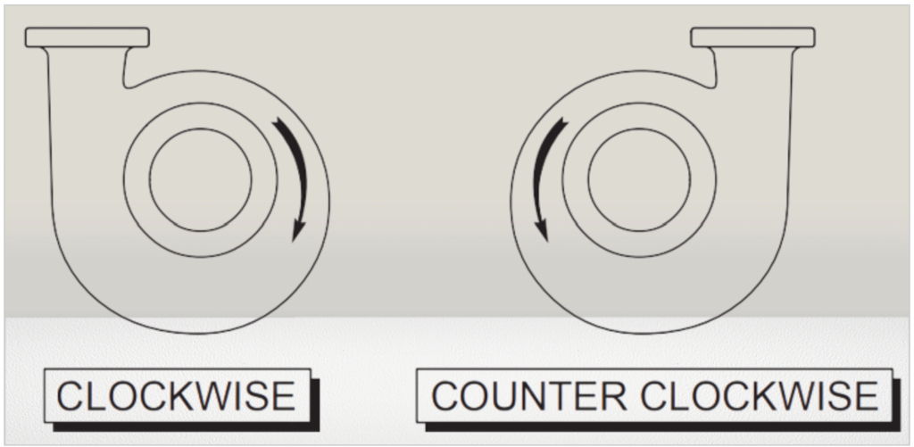
The Pump Case:
To prevent water from splashing everywhere, you’d put a case around the impeller. The case is usually spiral-shaped, like a snail shell, and it helps control the direction in which the pump spins.
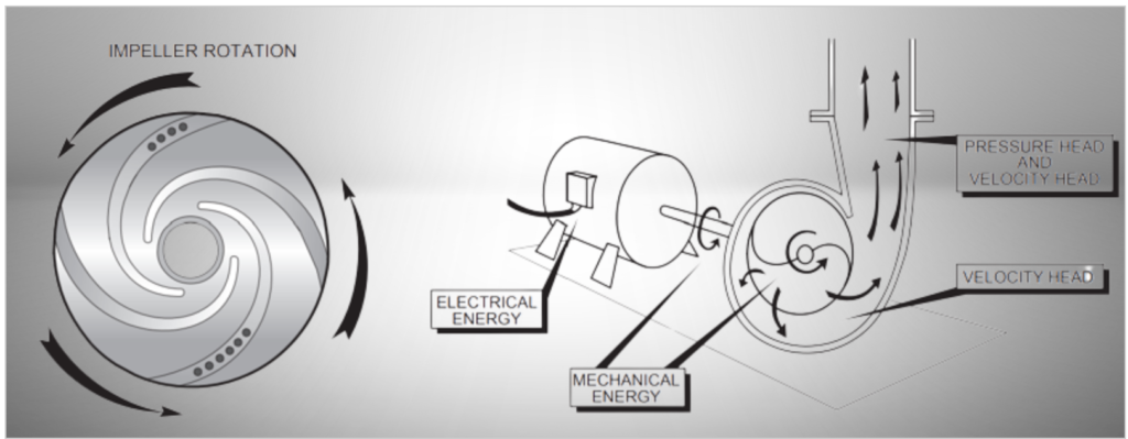
Pump Rotation:
So, in short, centrifugal pumps work based on two ideas:
- They transfer energy from the impeller to the water.
- They use spinning force to push the water out of the impeller.
Centrifugal Pumps Configuration:
Centrifugal pumps come in three main configurations, each serving different purposes.
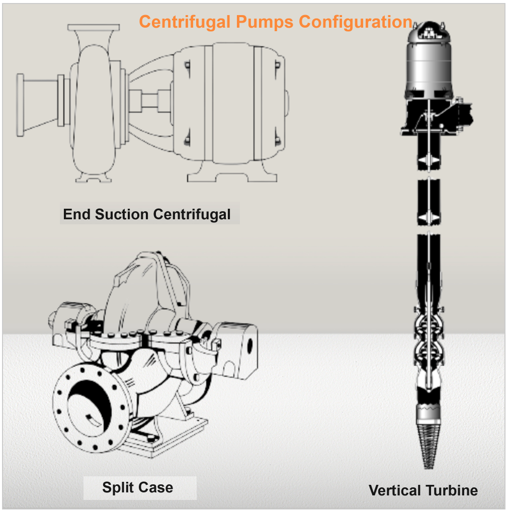
1. End Suction Centrifugal Pumps
These are the typical centrifugal pumps that most people are familiar with. They come in two types:
- Close-Coupled: These pumps are compact, with the pump impeller placed directly onto the motor shaft. They are less expensive and save space, having one shaft and one set of bearings, those of the motor.

- Frame-Mounted: These have a separate shaft and bearings from the motor, necessitating a coupling to transfer energy from the motor to the pump. They are more spacious compared to close-coupled pumps.
2. Split Case Pumps
These pumps are distinct due to their design allowing half of the case to be removed, giving full access to the rotating assembly. This feature makes them suitable as fire service pumps and circulation pumps in medium-to-large communities, for instance, the circulation pumps in Nome and Fairbanks.
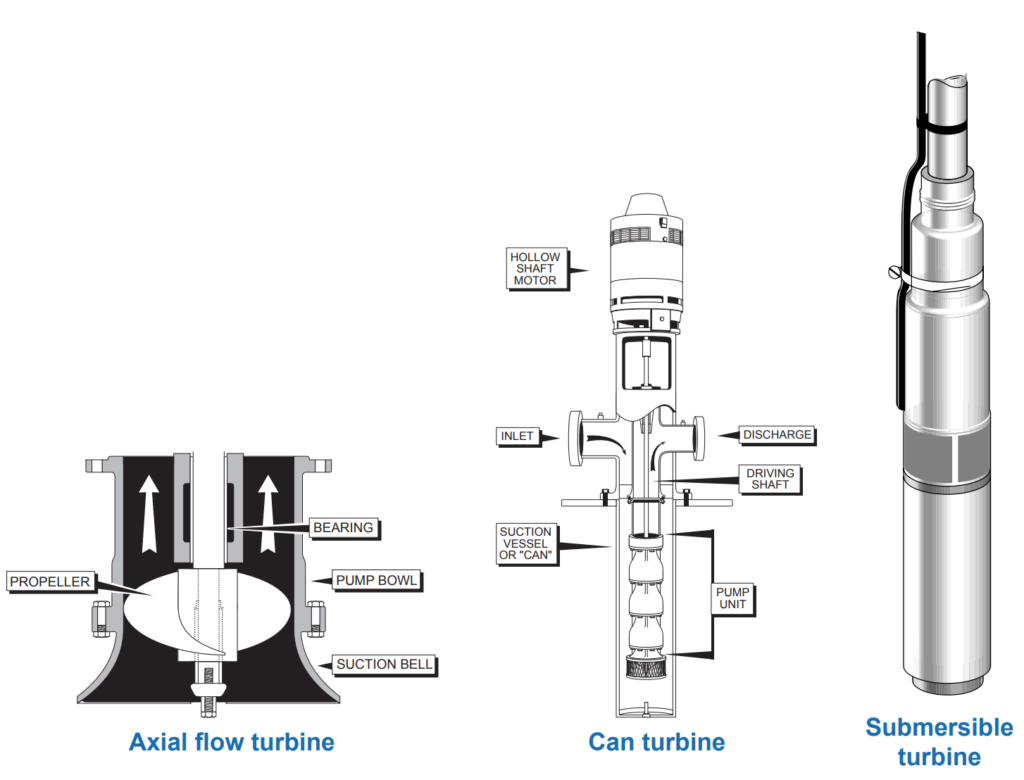
3. Vertical Turbines
These come in four styles: line shaft, axial flow, can turbine, and submersible turbine. The primary distinction between vertical and submersible turbines is the motor’s placement, while the pumping assembly remains consistent. They are prevalent in rural communities in Alaska, and the submersible ones can range from 5 gpm to 100 gpm or more.
In conclusion, the configuration of centrifugal pumps—whether it’s end suction, split case, or vertical turbines—is determined by their application and the specific requirements of the system they are integrated into.
Components of End suction Centrifugal and Split Case:
Certainly, let’s break down the components of end suction centrifugal and split case pumps:
Components Common to End Suction Centrifugal and Split Case Pumps:
1. Shaft and Bearings:
- The shaft transfers energy from the motor to the impeller.
- Common shaft materials are high carbon steel and stainless steel.
- Bearings support the shaft, handling thrust loads (along the shaft) and radial loads (at right angles to the shaft). These bearings may or may not be part of the motor.
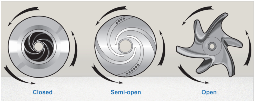
2. Impellers:
Impellers play a crucial role in transferring energy from the shaft to the water. Impellers can have different configurations:
- Closed Impeller: Has shrouds both in the front and back.
- Semi-Open Impeller: Features a shroud only in the back.
- Open Impeller: Lacks shrouds.
The choice of impeller type depends on specific pump conditions and is determined by the manufacturer.
3. Wear Rings:
- Closed impellers are positioned very closely to the case, leading to wear on the case as materials move from the high-pressure side to the low-pressure side of the impeller.
- To protect the case, wear rings made of brass or stainless steel are inserted into the case.
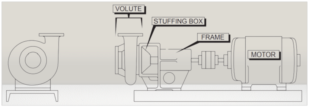
4. Volute Case:
Surrounding the impeller, the volute case collects the water thrown from the impeller and directs it in a single direction.
5. Backing Plate:
- Positioned behind the volute case, the backing plate seals the back of the volute case area.
Components Specific to End Suction Centrifugal Pumps:
6. Stuffing Box:
Attached to, and sometimes part of, the backing plate, the stuffing box is where material is placed to control the leakage of water from around the shaft. The material used in the stuffing box can be either packing or a mechanical seal.

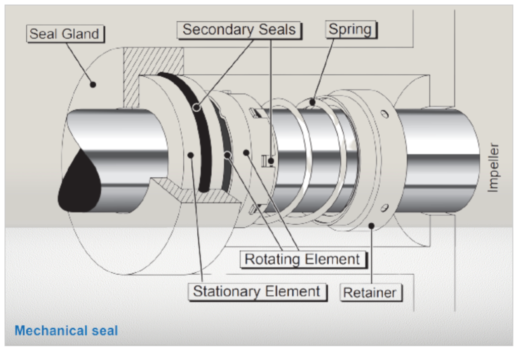
7. Packing/Mechanical Seals:
Both packing and mechanical seals serve the same purpose of controlling leakage through the stuffing box. Packing is typically composed of fiber materials, such as cotton, along with lubricants like graphite or TeflonTM. Mechanical seals consist of two finely machined surfaces, one hard and one soft, to prevent water from leaking.

8. Packing Gland:
- To apply pressure on the packing and control leakage, a packing gland is used. It consists of two metal pieces located at the back of the stuffing box.
9. Lantern Ring:
Sometimes, it’s necessary to lubricate and cool the packing with external water or oil, referred to as seal water or flush water. Seal water is introduced into the stuffing box through the lantern ring, often made of brass with holes to allow the easy passage of water.
10. Shaft Sleeve:
A shaft sleeve, made of brass or stainless steel, is installed to protect the shaft from damage due to the packing.

In summary, these components work together to enable the efficient operation of both end suction centrifugal and split case pumps, allowing for the transfer of energy from the motor to the impeller and ultimately into the water.
How to do Piping of End suction Centrifugal and Split Case?
Following are essential components and considerations in piping systems associated with end suction and split case pumps, especially focusing on suction lift conditions.
Suction Conditions:
End suction and split case pumps can operate in either suction lift or suction head conditions, each affecting the piping system differently. Suction lift condition is more challenging.
Suction Piping:
- In suction lift conditions, a foot valve, typically a large globe valve, is necessary to maintain pump prime.
- The suction piping should be designed with a size larger than the pump inlet, with smooth materials and fittings.
- Only gate or ball valves should be used as isolation valves on the suction side to avoid high headloss, caused by butterfly valves.
- The piping is reduced to meet the pump connection using an eccentric reducer to avoid air accumulation.
Discharge Piping:
- Discharge side starts with a concentric reducer to increase the pipe size.
- An isolation valve (preferably a gate or ball valve) is installed, and a spool or expansion joint is placed between the valve and the pump to reduce repair costs.
Flow and Pressure Control:
Ball and wide body globe valves are utilized to manage flow, pressure, and to mitigate water hammer during shutdown.
Check Valve:
Installed in the discharge line to prevent backflow through the pump, unless there’s a flow or pressure control valve, rendering it unnecessary.
Gauges:
Placed on both suction and discharge sides to monitor pump operating conditions. Equipped with ball valves at the base for easy replacement and longevity.
Seal Water:
Typically supplied from the discharge of the volute case. If obtained from another source, a pressure gauge should be installed in the seal water line to ensure correct flow direction, and backflow protection is provided with an air gap.
Additional Information:
- Operational Monitoring and Maintenance:
- Regular inspection and maintenance of all valves, gauges, and joints are essential to detect and fix any leaks, wear, or damage.
- The operating conditions monitored by the gauges should be regularly logged and assessed to detect any deviations from normal operation promptly.
- Proper lubrication and alignment of the pump and motor are also critical for optimal operation.
- Safety:
- Adequate safety measures, including proper lock-out/tag-out procedures and protective gear, should be observed during maintenance and repair activities to prevent accidents or injuries.
Components of Vertical Turbine Pumps:
Vertical turbine pumps, including line shaft and submersible turbines, are a specialized type of pump where the impellers are submerged in the fluid to be pumped. Below is a brief summary and description of the major components and their functions.

- Inlet/Suction Bell:
- The starting point for the fluid entering the pump.
- It directs the water into the pump bowl.
- Pump Bowl:
- Comparable to the volute case on an end suction centrifugal pump.
- It houses the impellers and is where the kinetic energy is transferred to the fluid.
- Impellers:
- Most vertical turbines have multiple impellers.
- Each impeller, along with its associated pump bowl, constitutes a pump stage.
- Adding more stages increases the discharge pressure but does not affect the flow rate.
- Column:
- It carries water from the pump bowl to the discharge head.
- It houses the pump shaft, which may be lubricated with water or oil.
- Discharge Head:
- A large cast iron component at the top of the pump.
- Changes the flow direction from vertical to horizontal.
- Houses the stuffing box and contains the mechanical seal or packing to prevent leakage.
- Motor:
- Located on top of the discharge head.
- It drives the pump shaft and can be removed for maintenance by loosening a nut located on the top.
Piping of Vertical Turbine
Vertical turbine pumps do require specific considerations related to their piping and operational conditions due to their vertical structure and submerged operation. Here are summaries and further clarifications.

1. Reversal of Flow:
- Issue:
- When the pump is shut down, the water tends to flow back down the column or drop line due to gravity.
- Solutions:
- Line Shaft Turbines: These turbines are equipped with special non-reversing ratchets in the motor. This mechanism prevents the pump from spinning backwards when water runs back down, protecting the equipment from potential damage.
- Submersible Turbines: Smaller submersible turbines usually have a check valve at the top of the pump. This valve stops the water from running backward through the pump, preventing reversal of flow.
2. Air Control:
- Issue:
- Contamination risk exists due to the potential entry of external agents through the stuffing box into the discharge line.
- Solution:
- An air valve is installed on the discharge line. This valve allows air in to prevent contamination from entering and, upon pump startup, lets the air out to facilitate proper flow.
3. Flow – Pressure Control:
- Approach:
- Similar to end suction centrifugal pumps, controlling the flow and pressure in vertical turbine pumps is done using wide body globe valves and butterfly valves. These valves allow for precise control of the flow rate and pressure within the system.
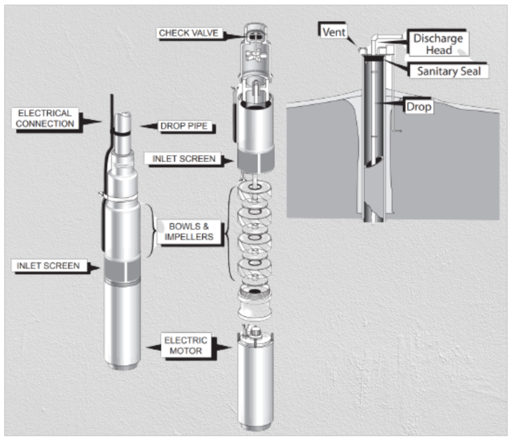
Submersible Turbine Components
Following are the component of submersible turbine.
- Inlet:
- The inlet is the entry point of water into the submersible turbine pump.
- It is situated between the pump and the motor.
- The water entering through the inlet moves through pump bowls which, in most cases, are identical to those in line shaft turbines.
- The bowls house the impellers, which impart energy to the water to move it through the pump.
- Drop Pipe:
- After the water moves through the pump bowls, it then travels up through the drop pipe.
- The drop pipe guides the water from the pump bowls upward, counteracting the force of gravity.
- It is crucial for this component to be robust and leak-free to ensure efficient and reliable operation of the pump.
- Discharge Head:
- The water eventually exits the system through the discharge head located at the top of the drop pipe.
- The discharge head is responsible for redirecting the flow of water from vertical to horizontal as it exits the pump system and enters the connected plumbing or distribution system.
Read Also: What is Cavitation in Pump?
2. Positive Displacement Pumps
Mostly Positive Displacement Pumps are used in Small Water Systems. Always keep discharge and suction valves open when using these pumps. Closing them can be dangerous to both people and equipment.
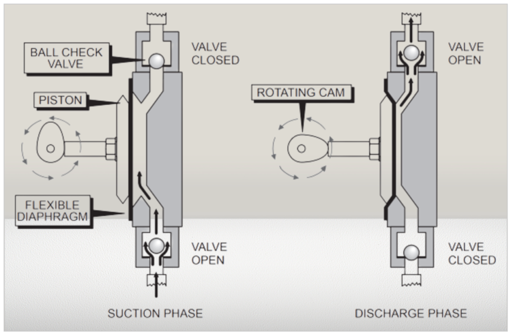
Diaphragm Pumps:
A diaphragm pump has a few key parts:
- A chamber that moves the fluid.
- A flexible diaphragm, powered either electrically or mechanically.
- Two valves: one for suction and one for discharge.
Here’s how it works:
The diaphragm pulls back, creating a vacuum inside the chamber. This vacuum closes the discharge valve and opens the suction valve. Fluid is then drawn into the chamber. When the diaphragm pushes forward, the pressure rises. This closes the suction valve and opens the discharge valve, pushing the fluid out. This process repeats, moving the fluid continuously.
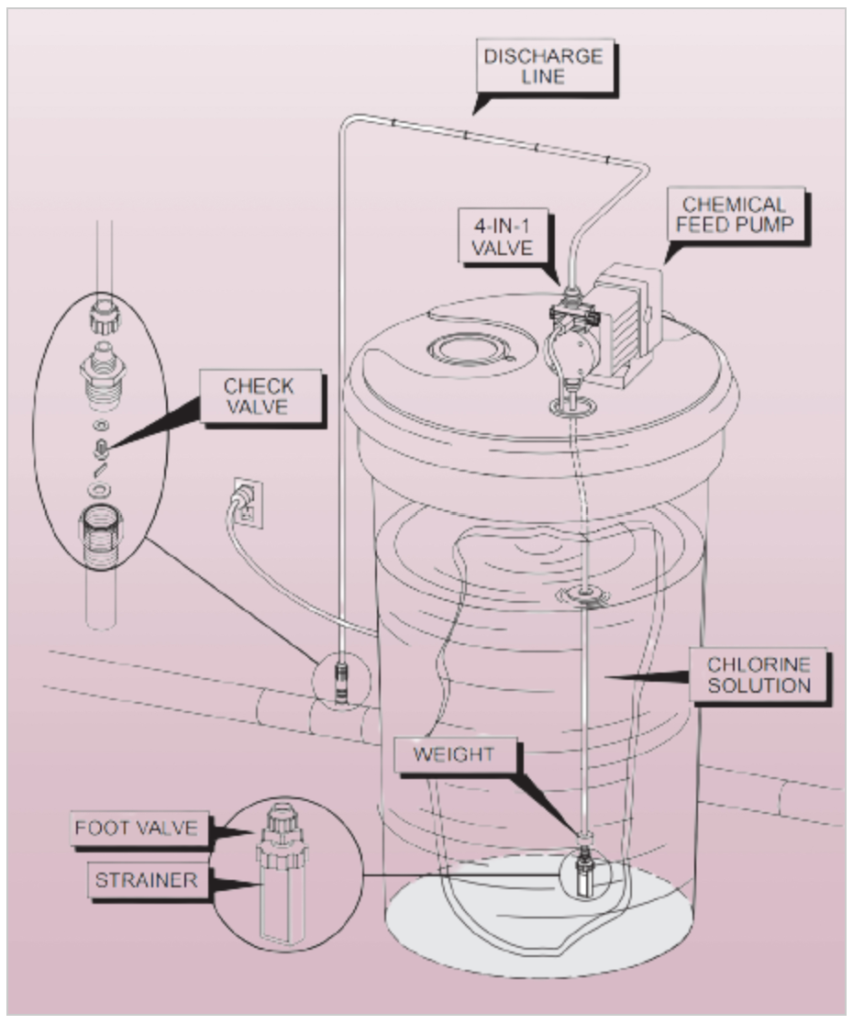
Piping System Basics
For diaphragm pumps moving chemicals, the pipes are straightforward:
- The suction pipe has a foot valve and a filter.
- The discharge pipe has a check valve at its end.
Purpose of these parts:
- The foot valve makes sure the pump doesn’t lose its prime.
- The check valve stops water from going backward into the storage tank.
2. Peristaltic Pumps:
Peristaltic pumps are specialized pumps used to move various liquids such as chemicals and thick substances. It does this by compressing a flexible tube containing the fluid through which it passes; to do this it employs a rotating part with rollers or shoes attached that pressurizes it and forces any part it touches close up, forcing its contents through, similar to when you squeeze toothpaste from its tube.
Cost-Efficient Design
One great advantage of peristaltic pumps is their cost-efficient design. Since these pumps do not touch liquid directly, construction costs are lower. Furthermore, maintenance is easier as there are no costly parts such as valves or seals that may need replacement over time; you only need to worry about replacing tubes or hoses within them as maintenance items compared to worrying about replacing expensive pump components like valves or seals that often need replacing in other pumps.
Tubing Selection Is Key
When selecting tubing for use with a peristaltic pump, selecting the appropriate material is of vital importance. Tubing should be durable enough to withstand whatever chemicals exist within the liquid being pumped; commonly used materials include polyvinyl chloride (PVC), silicone rubber and fluoropolymer; these have various trade names such as Tygon(tm) and Viton(tm), with differing degrees of resistance against different chemicals.
Versatility and Precise Flow Control
Peristaltic pumps are highly adaptable. From thin liquids to those containing chunks, these pumps can handle them all and make them useful in many industries, including pharmaceuticals, wastewater treatment and food processing. In addition, peristaltic pumps excel at precisely controlling how much liquid moves through them: you can simply adjust their speed to control this accurately.
Peristaltic pumps offer two great advantages over other forms of pumping: low maintenance costs and minimal downtime. Plus, many are self-priming; that means they can begin pumping without special assistance or priming requirements – something which is extremely useful if you want to get things going quickly.
Peristaltic pumps are low-cost and user-friendly pumps designed to move fluids across industries efficiently and cost effectively. Simply select tubing with appropriate properties for the task at hand to have a reliable way of moving fluids.
3. Progressive Cavity Pumps: An Overview
Progressive cavity pumps are a type of pump used to move liquids by employing a rotating screw-rotor within a stationary stator, with its pumping speed directly related to how fast its rotor spins. They’re used for moving any liquid that contains suspended solids; such as thick substances like sludge. Furthermore, progressive cavity pumps allow users to precisely measure large volumes of chemicals.
How They Work
A progressive cavity pump consists of a rotating rotor covered in “humps,” which rotates within a fixed stator. As it turns, these “humps” move through cavities made out of synthetic rubber material to squeeze material out of the pump in much the same manner that peristaltic pumps do; similarly to how peristaltic pumps function. These pumps must always contain some sort of fluid to stay lubricated and should never be operated when there’s an obstruction like a closed valve is blocking their flow.
Progressive cavity pumps are widely recognized for their exceptional ability to move viscous fluids and substances containing solids efficiently and safely, offering reliable transport while enabling precise flow rate control. As with any pump, however, it’s imperative that proper operating procedures be observed in order to maximize both effectiveness and safety during their use.
Water Pump Types FAQs:
What are the different types of water pumps available in the market?
How does a centrifugal pump differ from a positive displacement pump?
When should I use a submersible pump over a surface pump?
What is the advantage of using a diaphragm pump?
How do piston pumps work, and in what applications are they commonly used?
What are the key differences between a centrifugal pump and a jet pump?
Can I use a centrifugal pump for pumping thick or viscous liquids?
What is the importance of pump efficiency, and how is it measured?
What safety precautions should I follow when installing and maintaining a water pump?
What are some common issues that can affect the performance of water pumps, and how can they be addressed?
Are there specialized pumps designed for specific industries or applications?
What factors should I consider when selecting a water pump for a particular application?
Discover more from PAKTECHPOINT
Subscribe to get the latest posts sent to your email.