15.1 Pressure Gauges shall be dial type, acrylic crystal, and stainless steel and monel bushed rotary movements. Gauges shall have moisture-proof, plain cases with screwed rings and bronze socket with wrench flat and copper alloy bourdon. Gauges shall comply with ASME B40.100.
15.2 Temperature Gauges shall be adjustable dial type aluminum case with acrylic lens, die cast aluminum adjustable joint with locking device. Movement shall be precision geared brass. Stem shall be brass for separate socket. Scale shall be non-reflective aluminum with etched markings and a temperature range of -1.1 to 82°C.
15.3 Backflow preventer shall be reduced pressure principle type complying with ASSE 1013, suitable for continuous pressure application. Outside screw and yoke gate valves shall be included on inlet and outlet, and strainer on inlet; test cocks; and pressure-differential relief valve with ASME A112.1.2 air- gap fitting located between two positive-seating check valves.
Backflow preventerBackflow preventer
15.4 Expansion tanks shall be welded carbon steel, rated for 150 psig working pressure. Separate air charge from system water to maintain design expansion capacity by a flexible diaphragm sealed into tank. Drain fitting and taps shall be included for pressure gage and air-charging fitting. Vertical tanks shall be supported with steel legs or base, horizontal tanks with steel saddles. Tank shall be factory fabricated and tested with taps and supports installed and labeled according to the ASME BPVC.
15.5 Pressure Reducing Valve. Diaphragm-operated, bronze or brass body with low inlet pressure check valve, inlet strainer removable without system shutdown, and noncorrosive valve seat and stem. Select valve size, capacity, and operating pressure to suit system. Valves shall be factory set at operating pressure and have capability for field adjustment.
Pressure Reducing Valve
15.6 Pressure Relief Valve. Diaphragm-operated, bronze or brass body with brass and rubber, wetted, internal working parts; shall suit system pressure and heat capacity and shall comply with the ASME Boiler and Pressure Vessel Code, Section IV.
Relief Valves
Relief valves are designed to open at a preset pressure (or temperature) level and relieve the system when it has exceeded the desired level. The valve’s relief of elevated liquid, gas, or steam pressures prevents damage to the system. We offer a wide selection of relief valves for any application.
Pressure Relief Valve
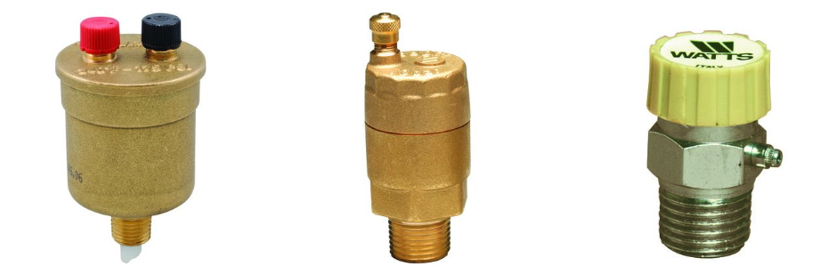
15.7 Air Vents
Air vents are designed for use on heating systems. Our line includes products such as high-capacity air vents that provide automatic air venting for hot or cold water distribution systems and models with a manual vent feature for fast venting of residential and commercial systems.
15.7.1 Manual air vent shall be bronze body with nonferrous internal parts, 150-psig, manually operated with screwdriver or thumbscrew with a 1/8 inch discharge connection and ½” inlet connection.
15.7.2 Automatic air vents shall be designed to vent automatically with float principle; bronze body and nonferrous internal parts, 150-psig with a 1/4 inch discharge connection and ½” inlet connection.
15.8 Strainers
Strainers
15.8.1 Size 2“ and under shall be threaded cast iron body, Y pattern with bolted cover, perforated stainless steel basket and bottom drain connection per ASTM A126, Class B.
15.8.2 Size 2½” and larger shall be flanged cast iron body, Y pattern, 150 psig working pressure per ASTM A126, Class B.
15.8.3 Screen free area shall be a minimum of three times the area of the inlet pipe. Valved drain and hose connection shall be provide off strainer bottom blow-off tapping.
Strainers
15.9 Chemical Feeder Tank. Bypass chemical feeder tank shall be of welded steel construction; 150 -psig working pressure, 19 liter capacity; with fill funnel and inlet, outlet, and drain valves. Chemicals shall be specially formulated, based on analysis of makeup water, to prevent accumulation of scale and corrosion in piping and connected equipment.
15.10 Flexible Connectors. Flexible connectors shall be stainless steel bellows with woven, flexible, bronze, wire-reinforcing protective jacket; 150 psig minimum working. Connectors shall have flanged- or threaded-end connections to match equipment connected and shall be capable of 20-mm misalignment.
15.11 Execution. Install water specialties in accordance with manufacturer published instructions.