1. SCOPE
2. REFERENCES
3. DEFINITIONS
4. GENERAL SYSTEM DESIGN
4.1 Capacity Design Basis 4.2 Minimum Residual Pressure 4.3 Flow Rates 4.4 Pressure
5. FIRE PROTECTION WATER SYSTEM
5.1 Design Basis 5.2 Storage Capacity 5.3 Fire Water Tanks 5.4 Pump Systems 5.5 Underground Fire Service Mains 5.6 Hydrants 5.7 Fixed Monitors 5.8 Hose Reels 5.9 Valves 15.10 Standpipe and Hose Stations
6. FIRE EXTINGUISHERS
6.1 General 6.2 CO2 Fire Extinguishing Systems
7. FOAM SYSTEMS
8. FIXED DRY AND WET CHEMICAL FIRE EXTINGUISHING SYSTEMS
9. TRAILER MOUNTED SYSTEMS 9.1 Fire Pump 9.2 Foam Generator
10. DELUGE SYSTEMS
10.1 Fixed Deluge Systems 10.2 Fire Water Demand 10.3 Contractor 10.4 Calculations 10.5 Performance Test 10.6 Piping Design 10.7 Manually Actuated Valves 10.8 Automatically Actuated Valves 10.9 Remotely-Actuated Valves 10.10 Valve Accessibility 10.11 Sign 10.12 Estimation of Coverage Densities 10.13 Layout of Deluge Heads
11. HALON 1211 AND 1301 FIRE EXTINGUISHING SYSTEMS
12. AUTOMATIC FIRE DETECTION SYSTEMS
13. COMPUTER AND DATA PROCESSING INSTALLATIONS
14. FIRE ALARM SYSTEMS
TABLE I Water Flow Requirements For Manual Fire Fighting
Table II Allowance For Supplemental Hose Streams
Table III Suggested Minimum Residual Pressures for Common Systems and Equipment
1. Scope
This standard describes the main components of a typical fire protection system for plants, laboratories,
warehouses, and office buildings and out-lines general principles for their design and performance.
2. References
Reference is made in this standard to the following documents. The latest issues, amendments, and
supplements to these documents shall apply, unless otherwise indicated.
E29-C01 Cathodic protection
P01-E15 Pressure Testing of Piping Systems and Lay-up Procedures
P13-C02 Underground Piping Fabrication and Erection
NFPA
NFPA 10, “Portable Fire Extinguishers”
NFPA 11, “Low Expansion Foam and Combined Agent Systems”;
NFPA 11A, “Medium and High Expansion Foam Systems”;
NFPA 11C, “Mobile Foam Apparatus”;
NFPA 12, “Carbon Dioxide Extinguishing Systems”
NFPA 12A, “Halon 1301 Fire Extinguishing Systems,”
NFPA 12B, “Halon 1211 Fire Extinguishing Systems
NFPA 14, Standpipe and Hose Systems
NFPA 16, “Deluge Foam-Water Systems and Foam-Water Spray Systems”
NFPA 17, “Dry Chemical Extinguishing Systems”;
NFPA 17A, “Wet Chemical Extinguishing Systems”
NFPA 20, Fire Pumps, Centrifugal
NFPA 24, Installation of Private Fire Service Mains and Their Appurtenances
NFPA 25, Inspection, Testing, and Maintenance of Water-Based Fire Protection Systems
NFPA 30, Flammable and Combustible Liquids Code
NFPA 72A, “Local Protective Signaling Systems for Guard’s Tour, Fire Alarm and Supervisory Service”
NFPA 72C, “Remote Station Protective Signaling Systems”;
NFPA 72D, “Proprietary Protective Signaling Systems”
NFPA 72E, “Automatic Fire Detectors”
NFPA 75, “Electronic Computer/Data Processing Equipment”
NFPA 231, “General Storage”
NFPA 231C, “Rack Storage of Materials.”
Threads (NH) which conform to NFPA 1963
American Petroleum Institute (API)
620, Design and Construction of Large, Low-Pressure Storage Tanks
650, Welded Steel Tanks for Oil Storage
NEMA
NEMA standard MG-1
Underwriters’ Laboratories
OSHA, Occupational Safety and Health Administration (United States)
OSHA, Subpart L, 1910.160, 1910.163
OSHA 1910.141
OSHA, Subpart L, 1910.160, 1910.163
OSHA, Subpart L, 1910.160, 1910.161
OSHA, Subpart L, 1910.160, 1910.162
OSHA, Subpart L, 1910.160
OSHA, Subpart L, 1910.161
OSHA, Subpart L, 1910.164
OSHA, Subpart L, 1910.165
3. Definitions
For the purpose of understanding this standard, the following definitions apply.
Area.
A hypothetical fire protection area in a process facility. It is used for the purposes of sizing fire water
systems and to prevent spread of fire from one area to another. For the purposes of defining process areas
only, a process area facility shall include any facility where hydrocarbons are produced, processed, stored,
or loaded, with the exceptions of well heads. Otherwise, bulk plants and fuel terminals are considered
nonprocess areas
Capacity Design Basis of a Fire Water System.
That flow rate which is needed to supply the highest
calculated fire water demand risk area served by the system.
Combustible Gas.
Any gas that can form an ignitable mixture with air.
Combustible Liquid.
A liquid that has a flash point greater than 54 deg C (130 deg F).
Combustible Liquid.
A liquid that has a flash point equal to or less than 37.8 deg C, as defined in NFPA
30. Combustible liquids shall be subdivided into three categories.
Combustible Liquid Class II.
A liquid that has a flash point above 37.8 deg C, and below 60 deg C, as
defined in NFPA 30.
Combustible Liquid Class IIIA.
A liquid that has a flash point above 60 deg C,, and below 93 deg C, as
defined in NFPA 30.
Combustible Liquid Class IIIB.
A liquid that has a flash point at or above 93 deg C, as defined in
NFPA 30.
Fire Water System.
A fire water system is a piping system for distributing fire water to facilities
within the scope of this Standard. It includes a supply source, storage, pump suction piping, fire water
pumps, jockey pumps, discharge piping, fire water distribution piping, branch piping, associated fixed fire
protection equipment, valves, and fittings.
Flammable Liquid.
A liquid that has a flash point equal to or less than 37.8 deg C, as defined in NFPA 30.
Residual Pressure.
Pressure of water at a specific flowing condition.
4. Water Supply System Design for Fire Fighting
4.1 Capacity Design Basis
4.1.1 A fire water system shall be designed to provide the maximum flow rate requirement of any single
area served by the system. The capacity design basis of the system is set by the area having the highest
flow rate requirement.
4.1.2 Fire water systems shall be analyzed using computer software specialized for cross loop flow
analysis of fire water systems to assure that the system will meet flow-rate and residual pressure
requirements at each piece of fire protection equipment.
4.1.3 Pressure-drop calculations shall be based upon Hazen-Williams formulae. The following flow factors
(C-factors) shall be used:
Cement-Lined Steel C = 130
90/10 Cu/Ni C = 140
Reinforced Thermosetting Resin Pipe C = 135
4.1.4 Prior to introducing hydrocarbons, actual flow-testing of the fire water system shall be done to confirm
that the required design flows, residual pressures, and other system tests and checks per NFPA 25 are
achieved. The flow test shall be witnessed by the authorized representatives. Deficiencies shall be
corrected prior to final acceptance. A record of the flow test shall be provided for plant files.
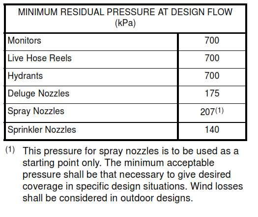
4.2 Minimum Residual Pressure
Fire water systems shall be designed to provide the minimum residual pressure at the hydraulically most
remote piece of fire fighting equipment in each risk area assuming (a) water flow to the fire fighting
equipment in the risk area meets the requirements of this Standard and (b) the specific piece of fire
fighting equipment is operating at its required flow. Residual pressure at individual equipment shall not
exceed 1140 kPa.
4.3 Flow Rates
Table I Water Flow Requirements For Manual Fire Fighting
| OCCUPANCY OF FIRE AREA | REQUIRED FLOW RATE |
| Open process areas handling Class I flammable liquids or Class II combustible liquids. | 0.20 L/m2s of the area at grade that contains structure or equipment which would require cooling and which is within 7.5 m of the largest probable liquid spill area but need not exceed
575 L/s. See Note 1. |
| Open process areas handling Class
III combustible liquids. |
0.17 L/m2s of the area at grade that contains structure or equipment which would require cooling and which is within 7.5 m of the largest probable liquid spill area but need not exceed
315L/s. See Note 1. |
| Open process areas handling gases under pressure. | 0.17 L/m2s of the area at grade that contains structure or equipment which would require cooling and which is within 25
m of the possible release point but need not exceeding 220 L/s. |
| Enclosed process areas handling flammable or combustible liquids. | 0.23 L/m2s of the building floor area. If building is divided by 3 hour (minimum) rated fire barrier walls and drainage is controlled to prevent spread of fire between areas, only largest floor area need be considered. Maximum flow rate need not
exceed 575 L/s. |
| Storage of flammable and combustible liquids in atmospheric tanks. | 0.10 L/m2s of the liquid top surface (Note 2) of the involved tank plus 0.07 L/m2s of the shell and roof surface for 1/4 of each adjacent tank within 7.5 m of the considered tank. |
| LPG storage tanks and vessels. | 0.17 L/m2s of the vessel exterior surface for all refrigerated tanks or pressure vessels within a group with shell-to-shell spacing of less than 7.5 m. |
| Warehouses. | Warehouses containing flammable or combustible liquids, 0.40
L/m2s of the floor areas but need not exceed 315 L/s. Warehouses containing ordinary combustibles, 0.20 L/m2s of the floor areas, but need not exceed 190L/s (Note 3). |
| Building, offices, labs, and similar structures. | 0.20 L/m2s of the floor areas but need not exceed 190 L/s. |
Notes
(1) Anticipated spill area within process structure shall consider drainage and curbing provided.
(2) Open type floating roof tanks with foam dams shall consider only area between foam dam and shell.
(3) For warehouses that contain ordinary combustibles and flammable or combustible liquids, flow rate for each area shall be calculated separately. Highest flow rate shall be used.
Table II
Allowance For Supplemental Hose Streams
|
OCCUPANCY OF FIRE AREA |
FLOW RATE (L/s) |
| Process areas handling flammable or combustible liquids | 126 |
| Process areas handling flammable gases. | 95 |
| Tank or pressure vessel storage | 95 |
| Warehouse containing flammable or combustible liquids | 63 |
| Buildings, all other occupancies | 32 |
Table III
Suggested Minimum Residual Pressures for Common Systems and Equipment
| SYSTEM OR EQUIPMENT | RESIDUAL PRESSURE | MEASURED AT |
| Calculated sprinkler, water spray, or foam system | As determined in system calculations, generally between 415 and 860 kPa | As specified in calculations, usually at base of system riser or at connection to main |
| Non-calculated sprinkler systems (see
Note 1). |
Elevation pressure, in kPa, to reach highest sprinkler head, plus 100 kPa, but not less than 350 kPa | At base of system riser |
| Fixed monitor | 700 kPa | At monitor base |
| Hydrant calculated sprinkler, water spray, or foam system directly feeding hose streams | 700 kPa | At hydrant |
| Hydrant feeding a fire truck | 140 kPa | At hydrant |
Note: For new installations, non-calculated sprinkler systems shall be provided only in buildings whose occupancy is classified as light or ordinary hazard. All other sprinkler systems shall be calculated.
4.4 Pressure
Pressures listed in this standard are gage, unless otherwise specified.
5. Fire Protection Water System
5.1 Design Basis
Every fire water system shall be supplied from dedicated fire water storage. The storage shall contain a volume of water sufficient to provide the design flow rate, for the duration stated below, to the most demanding area (capacity design basis). Tankage may be used for fire water and for utility water provided the suction connection for the utility water pumps is high enough on the tank to ensure the required fire water supply is available when utility water suction is starved. Bladder tanks are considered to be ground level storage tanks. Ponds and basins should be periodically inspected for buildup of sediment, etc., which could reduce capacity or plug pump intakes.
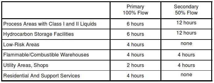
5.2 Storage Capacity
The required storage capacity shall be sufficient to provide fire water for durations as follows, with a primary supply providing 100% of the design basis flow and a secondary supply providing 50% of the design basis flow:
15.2.1 In locations where a reliable supply of water is available, provisions shall be made to provide a
minimum of 50% of the design flow indefinitely. An example would be seawater back-up to a fresh water
system.
5.2.2 The supply of fresh water may be reduced to 2 hours if 100% seawater back-up is provided.
5.2.3 When seawater is used, a chlorination, hypochlorination, or other system shall be provided to prevent
the growth of marine organisms in pump suctions, pump caissons, and other piping systems susceptible to
their growth. Systems shall be capable of being adjusted to provide down to 1 ppm of free chlorine to the
inlet of the source pump suction. A system shall be provided to monitor the chlorine concentration entering
the pump.
5.2.4 Fire Water Quality
It is preferable for the primary supply of water to be fresh water. If the water supply is brackish, chemical
injection or other means of water treatment should be considered in system design to reduce corrosivity,
scaling or fouling tendency, and other undesirable factors.
5.2.5 Cross Connections
Cross-connection of potable and nonpotable water systems should be avoided; however, where necessary,
the construction of nonpotable water systems shall be such as to prevent backflow or back siphoning into a
potable water system OSHA 1910.141). Devices such as Underwriters’ Laboratories listed “backflow
preventer” may be used. Local regulations should be consulted.
5.3 Fire Water Tanks
5.3.1 Design
Fire water storage tanks shall be in accordance with API 650 or API 620, as applicable.
5.3.2 Internals
The lining and internals of tanks shall be compatible with all types of water anticipated as being a source of
fire water.
5.3.3 Piping Connections
All piping connections to a tank used as a reservoir, other than suction lines to the fire water and jockey
pumps, shall be located at a point above the level required to contain the minimum volume.
5.3.4 Alarm
A fire water tank low level alarm shall be installed with annunciation at the appropriate manned control
facility.
5.4 Pump Systems
5.4.1 General
5.4.1.1 Fire pumps shall generally be designed and installed in accordance with NFPA 20.
5.4.1.2 If possible, pumps, drivers, and control equipment shall be listed or approved for use in fire pump
installations.
5.4.1.3 The number and size of fire pump units shall be based on calculated flow and pressure
requirements.
5.4.1.4 Facilities in which fire pumps are the only source of fire protection water shall have at least one
backup fire pump. Backup fire pump shall be equal in size to largest fire pump in system. There shall be at
least one diesel engine driven back up pump.
5.4.1.5 Fire pumps, drivers, controls, and special accessories shall be purchased as a package unit from
single source when possible to ensure that equipment is properly matched and in compliance with
applicable standards.
5.4.1.6 Fire pumps shall be located away from process units handling flammable liquids and gases and
protected from damage from fire or explosion. Fire pumps may be located in steam plants or utility
operating areas if sufficiently distant from process units.
5.4.1.7 Fire pumps, drivers, controls, and other critical components shall be housed in a building or
enclosure to protect them from weather. The room shall have artificial lighting, in accordance with
NFPA 20.
5.4.2 Pumps
5.4.2.1 Fire pumps shall be centrifugal type designed for water service.
5.4.2.2 Pump materials selected shall be suitable for the characteristics of the source water. If source
water is salt or brackish, pump material combinations shall be resistant to both chemical and electrolytic
corrosion.
5.4.2.3 Pump shall be capable of operating at any flow rate up to 150% of its nominal flow rating, without
exceeding the pump relief valve settings.
5.4.2.4 Pressure versus flow characteristics of pump shall conform to NFPA 20.
5.4.2.5 Pumps shall be sized such that its nominal rating is not less than 85% of the maximum design flow
rate that it will be required to supply to the facility.
5.4.2.6 If the water source is supplied to suction of pump at positive static pressure, such as from elevated
reservoir, above ground tank, or another piped system, the pump shall be horizontal or vertical split case
type.
5.4.2.7 Pumps 30L/s or less may be end suction type.
5.4.2.8 Suction piping to horizontal pumps shall be sized such that with all connected pumps operating
simultaneously at 150% of their nominal rating, the suction pressure at each pump inlet flange is not less
than 0 kPa.
5.4.2.9 Pumps at elevations higher than water level of suction source shall be vertical turbine type.
5.4.2.10 Fire water pumps shall have minimum flow protection (circulation relief) to prevent overheating of
the pump. The circulation relief shall be sized and arranged as specified in NFPA 20.
5.4.3 Drivers
5.4.3.1 Type
Fire pump drivers shall be diesel engines, electric motors, or steam turbines. The driver should be a diesel
engine, when there is only one pump. Gasoline or gas fueled engines shall not be used for fire pump
drivers.
5.4.3.2 Diesel Engines
5.4.3.2.1 Fire pump driver shall have net available power output equal to or greater than maximum required
to drive pump at rated speed under any condition of pump load.
5.4.3.2.2 Diesel engine output power shall be adjusted for elevation and maximum air temperature at
installation site.
5.4.3.2.3 Diesel engines not listed/approved for fire pump service shall have 10% safety factor applied to 4
hour power rating.
5.4.3.2.4 Diesel engine drivers shall have instrumentation that conforms to NFPA 20.
5.4.3.2.5 Engines shall have an overspeed shutdown device set at 20% above rated engine speed.
Engines shall have no other automatic shutdown device.
5.4.3.2.6 Each engine driver shall have its own dedicated water cooled heat exchanger arranged in
accordance with NFPA 20.
5.4.3.2.7 New or replacement installations shall not have radiator (air exchange) cooled engines.
5.4.3.2.8 Each engine driver shall have its own dedicated fuel supply tank, sized and arranged in
accordance with NFPA 20.
5.4.3.2.9 Diesel engines for fire pumps shall have a controller that is specifically listed for use with fire
pump service. If controlling a battery started engine, a dual battery charger shall be a part of the controller.
5.4.3.3 Electric Motors
5.4.3.3.1 Totally enclosed fan cooled electric motors complying with NEMA standard MG-1 shall be used to
drive fire pumps.
5.4.3.3.2 Electric motors shall be sized such that a rated voltage, the full load amperage rating shall not be
exceeded at any condition of pump load.
5.4.3.3.3 Electric motor drive fire pumps shall have a controller that is specifically listed for fire pump
service. The motor starter, over-current protection, and disconnect means shall be an integral part of the
fire pump controller.
5.4.3.3.4 Electrical feed line to electric motor drivers shall be routed either underground from source to the
motor controller, or such that line is protected from fire, explosion, or other event for which a fire pump may
be needed.
5.4.3.3.5 The branch circuit that feeds the fire pump motor shall be separate from and connected ahead of
plant power feeds such that plant electrical loads may be shed without loss of power to fire pumps.
5.4.3.3.6 Electric motors shall be selected and installed in accordance with NFPA requirements. Motor
controls shall have a circuit breaker with magnetic trip for short circuit protection. Unless specified
otherwise, motor overload protection shall not be permitted.
5.4.3.4 Steam Turbines
5.4.3.4.1 The exhaust from a steam turbine used to drive a fire pump shall be to the atmosphere, unless
specified otherwise.
5.4.3.4.2 Vertical turbines shall not be used.
5.4.3.4.3 Remote, instantaneous start from cold conditions shall be required.
5.4.4 Controls
5.4.4.1 Starting
5.4.4.1.1 Fire pumps which are primary fire protection water supply shall be arranged to start automatically
upon fire conditions.
5.4.4.1.2 Fire pumps which are part of secondary supply or are backups may be arranged for manual
starting if facility is continuously manned and at least one person per shift is trained and designated to
start pumps.
5.4.4.1.3 The fire pump controller shall initiate automatic starting upon sensing loss of pressure in
distribution system.
5.4.4.1.4 The pressure at which an automatic start initiates shall be 70 to 100 kPa lower than the lowest
pressure that is normally maintained in the distribution system.
5.4.4.1.5 Multiple automatic fire pumps shall have automatic start initiated at the same pressure for each
pump. Adjustable time delays in each fire pump controller shall stagger starting of multiple pumps. Electric
motor driven pumps shall preferably be started first. Subsequent pumps shall automatically start only if
pressure has not returned to above set pressure. There shall be a 5 to 10 second interval between starting
of each pump.
5.4.4.1.6 Fire pumps which are part of combined system that provides utility and fire protection water shall
be arranged for automatic start from external alarm signal, as well as from pressure loss. External alarm
signal shall be initiated automatically from fire detection systems, operation of fixed fire protection system,
and/or plant fire alarm system. Automatic start from loss of pressure shall be set at point below lowest
normal utility pressure to prevent starting fire pumps on high utility demand
5.4.4.2 Static Pressure Maintenance
5.4.4.2.1 Static pressure in distribution system shall normally be maintained by use of small pressure
maintenance (jockey) pump or utility pump.
5.4.4.2.2 Pressure maintenance pump(s) shall be sized to supply the largest incidental, non-fire or service
– flow rate from the system shall be at a pressure that will prevent automatic
starting of the fire pumps.
5.4.4.2.3 Fire pumps shall not be used as pressure maintenance pumps.
5.4.4.3 Stopping Pumps
Fire pumps may be arranged to stop automatically after all starting signals have returned to normal and
driver has run a minimum of 10 minutes (electric motor or steam turbine drivers) or 30 minutes (diesel
engine drivers).
5.4.4.4 Annunciation
5.4.4.4.1 Alarms for “Pump Operating” and monitored malfunctions shall be annunciated at constantly
attended location, such as control room or guard station.
5.4.4.4.2 Facilities which are not continuously manned or do not have guard service on premises during off
hours shall have alarms annunciated at remote, attended location off premises, such as an alarm service,
local fire or police station, or automatic phone service to key facility personnel.
5.4.5 Accessories
5.4.5.1 Discharge Pressure Gage
5.4.5.1.1 Fire pumps shall have discharge pressure gage connected at or near discharge connection from
pump.
5.4.5.1.2 Gage shall not be less than 90 mm in diameter.
5.4.5.1.3 Gage shall have pressure range up to twice working pressure of pump but not less than
1400 kPa.
5.4.5.2 Suction Gage
5.4.5.2.1 Except for vertical turbine pumps, all fire pumps shall have compound suction gage.
5.4.5.2.2 Suction gage shall be connected at or near suction connection to pump.
5.4.5.2.3 Suction gage shall not be less than 90 mm diameter.
5.4.5.2.4 Suction gage shall have pressure range from full vacuum up to twice working pressure of pump
but not less than 700 kPa.
5.4.5.3 Circulation Relief Valve
5.4.5.3.1 Pumps shall have circulation relief valve set to open below pump’s shutoff pressure and provide
sufficient flow to prevent overheating of pump.
5.4.5.3.2 Pumps 160 L/s and smaller shall have NPS 3/4 valves. Pumps larger than 160 L/s shall have
NPS 1 valves.
5.4.5.3.3 Diesel engine driven pumps which take cooling water from discharge of fire pump shall not
require circulation relief.
5.4.5.4 Safety Relief Valve
5.4.5.4.1 Pumps shall have safety relief valve if driven by diesel engine, steam turbine, or other variable
speed driver, or are capable of generating shutoff pressure above working pressure of distribution system.
5.4.5.4.2 Safety relief valve shall be connected between pump discharge and discharge check valve.
5.4.5.4.3 Relief valve discharge shall be to open waste or back to suction source. Relief valve discharge
shall not be piped back to pump suction.
5.4.5.4.4 Single safety relief connected to main shall not be acceptable.
5.4.6 Test Line
5.4.6.1 Each fire pump installation shall have a test line for flow testing each fire pump.
5.4.6.2 Test line shall have an annubar or orifice type flow element and differential meter calibrated to read
flow rate in test line.
5.4.6.3 Unless required by local authorities, hose valve headers shall not be provided for testing.
5.4.6.4 Installations with multiple fire pumps may have a single means of testing. Pumps shall be arranged
in accordance with NFPA 20. Valving shall be such that a single pump may be isolated for testing without
isolating remaining fire pumps from system.
5.4.6.5 Test line shall be capable of flowing up to 175% of nominal rating of largest pump without tripping
the relief valve..
5.4.6.6 If possible, discharge test line shall be routed back to suction source, tank, or reservoir to minimize
loss of water during testing.
5.5 Underground Fire Service Mains
5.5.1 Service Mains
5.5.1.1 Fire mains supplying sprinkler systems, standpipes, and hydrants are subjected to severe stress
during start-up and shutdown of fire pumps, hose steams, and hydrants; therefore, materials and
installation details shall comply with and/or NFPA standards.
5.5.1.2 A loop system of underground mains should be provided to assure more than one water supply
route for sprinkler systems and hydrants. Loop mains shall be sized, located, and equipped with sufficient
sectional valves to minimize the loss of water delivery capability resulting from a failure of any one section
of main.
5.5.1.3 Piping shall be sized to meet design demands. No pipe smaller than NPS 8 shall be installed in
underground mains, except branch lines to hydrants, sprinkler systems, and standpipes which shall be no
smaller than NPS 6. For very small demand sprinkler systems (e.g., less than ten sprinkler heads), smaller branch lines may be used provided that hydraulic calculations show that adequate water flow and
pressure will be supplied.
5.5.1.4 Only pipe and fittings listed by Underwriters’ Laboratories, or meeting equivalent specifications,
shall be used for fire main systems. Cement-lined cast or ductile iron centrifugally cast pipe and fittings,
reinforced concrete pipe, or plastic pipe are recommended.
5.5.1.5 The underground fire mains shall be provided with a flushing connection which discharges to a
sewer or drainage ditch if sediment-containing water is used.
5.5.1.6 Installing fire mains under buildings or other structures, or building new structures over existing
mains, shall be avoided to prevent structural damage and facilitate repairs in event of main failure.
5.5.1.7 All changes of direction of fire main piping shall be anchored by tie rods, pipe clamps, and/or
concrete thrust blocks.
5.5.2 Piping
5.5.2.1 The fire water system piping shall encompass all piping, fittings, and valves extending from the
supply source to the isolation valves for fixed fire equipment and entry points to buildings. The system
shall not include fire water piping within buildings, except for hydrotest requirements mentioned below.
5.5.2.2 Fire water mains shall meet NFPA 24.
5.5.3 Provisions shall be made to facilitate frequent inspection, testing, and maintenance as described in
NFPA 25.
5.5.4 Every fire water system, including sections of piping, fittings, valves, pumps, and drivers, shall be
designed to accommodate the failure of any one system component so that operation of the major part of
the system can be restored with minimum down time. Block valves shall be provided to isolate failed
components in accordance with the following:
5.5.4.1 Beginning from the downstream side of the suction valve on each fire water pump, the system shall
be designed to provide at least 50% of the required flow and pressure to the protected area upon isolation
of the failed component. Where the normal static suction pressure at the fire water pumps is 210 kPa or
greater, dual suction lines from the supply source to the fire water pumps shall be provided to ensure that
loss of one suction header will not result in loss of more than 50% of the design capacity.
5.5.4.2 Failure of a single element shall cause no more than four (4) fire protection devices (monitors,
hydrants, fixed spray systems, deluge systems, etc.), not counting live hose reels, to be removed from
service at a time..
5.5.4.3 When gate valves are used abovegrade, they shall be installed so that the stems are horizontal.
5.5.5 Material Selection
Piping shall be selected, protected, and installed as follows:
5.5.5.1 Piping materials for firewater systems are defined by Piping Line Class. Material may be steel,
galvanized steel, ductile iron, or reinforced plastic, to be determined later.
5.5.5.2 Piping for fixed water or foam piping or foam concentrate skid installations is also defined by Piping
Line Classes.
5.5.5.3 Piping shall be installed in accordance with SES P13-C02
5.5.5.4 Cathodic protection shall be provided in accordance with SES E29-C01.
5.5.6 Hydrotesting Requirements
Hydrotesting of new construction or renovation of fire protection systems shall meet the requirements of
SES-P01E15.
5.5.7 Fire Water Pump Suction Piping
5.5.7.1 Suction piping shall be installed abovegrade.
5.5.7.2 A pressure gauge shall be installed immediately upstream of each fire water pump.
5.5.8 Fire Water Pump Discharge Piping
5.5.8.1 Discharge piping and the discharge manifold (if any) shall be abovegrade from pumps to the
downstream side of all fire water pump and jockey pump discharge connections.
5.5.8.2 A pressure gauge shall be installed between the discharge flange of every fire water pump/jockey
pump and its isolation valve.
5.5.8.3 Pressure switches and pressure tap valves shall be installed downstream of the pump discharge
block valve.
5.5.8.4 Check valves shall be provided on the discharge of all fire water pumps upstream of the discharge
block valves. Check valves shall not be permitted elsewhere in the fire water system, except as required by
this Standard.
5.5.9 Distribution Piping
5.5.9.1 No distribution main piping shall terminate in a dead end. For branch piping, see 5.5.10 below.
5.5.9.2 The minimum permissible size of distribution piping is NPS 8 in process areas and NPS 6 in other
areas.
5.5.9.3 Within or near plant process areas, fire mains shall be installed underground. Depth of cover for fire
exposure protection shall be a minimum of NPS 6. However, greater depth may be required for surface
load distribution., Lines may be installed aboveground on sleepers in tankage and other offsite plant areas
and when over 7.5 m outside plant battery limits. Consideration must be given to drainage patterns,
exposures to fire, and vulnerability to mechanical damage in routing these lines. Sections of piping that are
located in fire-exposed areas shall be buried or fireproofed for two hours, assuming no-flow condition.
5.5.9.4 Locating fire water lines in major pipeways is not allowed.
5.5.9.5 An averaging flow meter for local meter hook-up shall be installed such that every fire water pump
may undergo flow tests without impairing the availability of the system. The meter shall be located in the
bypass piping from pump discharge to source of supply. The meter shall not restrict flow to the system. See
Figure 3
5.5.9.6 Flow measurement devices shall not restrict the design flows to any areas served by the fire water
system.
5.5.10 Branch Piping
5.5.10.1 Branch piping shall feed no more than four (4) fire protection devices, excluding live hose reels.
5.5.10.2 The fire devices located on a single branch line shall constitute no more than 50% of the devices
available to protect any single piece of process equipment.
5.5.10.3 Branch piping shall be buried.
5.5.10.4 The minimum size of any branch line shall be NPS 4, except as for a branch supplying one hose
reel may be a minimum of NPS 2 for a maximum length of 15 m.
5.5.10.5 Permanent connections to scraper traps, utility systems, safety showers, process equipment, or
vessels are prohibited.
5.5.11 Block Valves
5.5.11.1 All belowgrade block valves in plant areas shall either have their stems protruding abovegrade or
be equipped with position indicators abovegrade. Direct-buried block valves shall be post-indicator type.
5.5.11.2 All block valves shall be operable from abovegrade.
5.5.11.3 Block valves located on abovegrade piping shall be readily accessible.
5.5.11.4 Each fire water system block valve shall have a unique and individual number on or near the
valve to clearly identify it for isolation purposes and for reference on fire water system drawings. The
numbering system shall be coordinated with the Company Fire Protection Department.
5.5.11.5 If a valve box is provided, valve service and valve number shall be marked clearly and
prominently on the valve box entrance.
5.5.12 System Drawing
Every fire water system shall be represented on a layout drawing, to scale, showing fire water and foam
piping, sectionalizing and branch valves, foam tanks and proportioners, hydrants, monitors, deluge and
sprinkler systems, hose reels, fire boat connections, fire water tanks, pumps, and jockey pumps. For
orientation purposes, major structures and major pieces of process equipment shall be indicated and
identified on the drawing. The design basis capacity of the fire water system shall be stated on the
drawing. The drawing shall be kept up-to-date.
5.6 Hydrants
5.6.1 Hydrants shall as a minimum have an NPS-6 inlet connection.
5.6.2 Hydrants shall be listed for fire main service.
Note: Most UL listed and FM approved hydrants are limited to a maximum working water pressure of 1050
kPa. Industrial fire protection water systems are usually designed for maximum pressure of 1200 kPa or
greater. Care shall be taken to ensure that hydrants are suitable for system pressure.
5.6.3 Hydrants shall have at least two NPS 2 1/2 or larger hose connections.
5.6.4 Hydrants which supply fire trucks shall additionally have NPS-4 or larger pumper connection to
match plant standard.
5.6.5 Hose connections shall match the plant. When no local standards apply, connections shall be
American National Fire Hose Connection Screw Threads (NH) which conform to NFPA 1963.
5.6.6 The number of hydrants and their placement shall be capable of supplying the required flow within
170 m of fire area. Process unit loop shall be arranged such that at least one hydrant is pressured if any
section of the loop is depressured to perform system maintenance.
5.6.7 Hydrants that directly feed hose streams shall be located 15m to 30m from the area to be protected.
5.6.8 Hydrants that supply fire trucks shall be located along access roadways at 60 to 90 m intervals.
5.6.9 Hydrants shall be available on at least two sides of the area being protected.
5.6.10 Fire water hydrants shall be located independently of the fire water monitors.
5.6.11 Fire water hydrants are not normally located within process unit limits.
5.7 Fixed Monitors
5.7.1 Fixed monitors shall be located 15 to 22 m from the area which they protect.
5.7.2 Monitors shall be positioned such that all portions of fire area are within 30m of a monitor.
5.7.3 Monitor nozzles shall have a rated capacity between 32L/s 700 kPa nozzle pressure.
5.7.4 Monitors rated for flow rates above 32L/s may be used in special applications that require longer
reach or higher water application rates.
5.7.5 Fixed monitors shall be mounted to a hydrant or to their own pipe riser.
5.7.6 Pipe risers which feed fixed monitors shall as a minimum be NPS 6 and have an NPS 4 shutoff valve
directly below monitor base.
5.8 Hose Reels
5.8.1 Hose reels shall use hose that is not larger than NPS 1-1/2 diameter and shall be fitted with self
regulating valves to control the residual pressure at 1000 kPa.
5.8.2 Hose reels may be located in or adjacent to buildings or process areas, such that all areas intended
to be covered shall be within 10 m of the nozzle on the fully extended hose. Hose reels shall be accessible
under anticipated fire conditions.
5.8.3 Non-continuous flow type reels and hose racks shall use NPS 1-1/2 synthetic jacketed, lined,
collapsible fire hose.
5.8.4 Hose length shall be not less than 15 m and not more than 30 m.
5.85 Nozzles shall be of a type that is specifically listed for use in Class II service and shall have an integral
shutoff.
5.8.6 Hose reels shall be fed by piping from the fire water distribution system, arranged in accordance with
NFPA 14. Each hose reel shall have a readily identifiable shut-off or hose valve at the connection to the
piping.
5.8.7 Hose reels in outdoor locations shall be suitably protected from the detrimental affects of weather.
5.9 Valves
5.9.1 The fire protection distribution system should have sufficient valves such that no more than a total of
six hydrants, monitors, or fixed systems and no more than half of the protection in any considered fire area
would be out of service with any single line segment isolated.
5.9.2 Looped main shall have valve on either side of each connection from water supply to main.
5.9.3 Multi-looped systems shall have valving such that each line segment between junctions may be
isolated by closing no more than four valves.
5.9.4 Some line segments and long single loops may require intermediate isolation valves.
5.9.5 Non-looped branch mains which feed hydrants, monitors, and fixed systems shall have isolation
valve at point at which branch main connects to loop.
5.9.6 Branches which feed a single hydrant located within 3 m of looped main shall not require isolation
valve.
5.9.7 Valves in distribution system shall be gate, butterfly, or full ported ball type specifically intended for
water service.
5.9.8 Valve operators shall indicate valve position, open or closed.
5.9.9 Valves shall be listed or approved for fire main service, except if such valves are not reasonably
available and non-listed valves are acceptable to local authorities and insurance carrier.
5.9.10 Mains shall not have plug or globe type valves.
5.9.11 Butterfly, ball, and other quarter turn type valves shall be gear operated or otherwise arranged such
that valve cannot be moved from full open to full closed in less than 5 seconds.
5.9.12 Underground valves shall be equipped with indicating post assembly or roadway box and T-wrench
for operation.
5.9.13 Valve operators shall be clearly identified as to their purpose, accessible for maintenance, and
protected from mechanical damage.
5.10 Standpipe and Hose Stations
5.10.1 Hose standpipes are provided primarily to give convenient locations for the supply of water for small
hose streams inside buildings. The stand-pipe should be under water pressure at all times. Their use is
important in warehouse area; see NFPA 231, and NFPA 231C.” Standpipes may also be installed to supply
hose or hose connections or roof areas which would otherwise require excessively long hose lays.
5.10.2 Standpipe and hose stations shall meet the design requirements of NFPA 14, and OSHA, Subpart
L, 1910.160, 1910.163, and NFPA 20 for the pump test purposes.
6. Fire Extinguishers
6.1 General
The selection, installation, maintenance, and use of portable fire extinguishing equipment shall be in
accordance with NFPA 10, and OSHA, Subpart L, 1910.160, 1910.161.
6.2 CO2
Fire Extinguishing Systems
Carbon dioxide extinguishing systems shall meet the design requirements of NFPA 12, (OSHA, Subpart L,
1910.160, 1910.162) Carbon dioxide is not recommended for total flooding systems where there is a
potential for personnel exposure.
7. Foam Systems
The selection, design, and use of foam systems shall be in accordance with NFPA 11, NFPA 11A, NFPA
11C, and NFPA 16, and OSHA, Subpart L, 1910.160, 1910.163.
8. Fixed Dry And Wet Chemical Fire Extinguishing Systems
Fixed dry or wet chemical extinguishing systems shall meet the design requirements of NFPA 17, or NFPA
17A, OSHA, Subpart L, 1910.160.
9. Trailer Mounted Systems
Certain systems can be mounted on trailers to make them portable. This portability increases the flexibility
of the total fire fighting system, or allows the owner to purchase a limited number of items and be able to
extend the coverage.
9.1 Fire Pump
A complete engine driven pumping system similar to a fire truck only trailer mounted is an economical
alternative to a fire truck. These are commercially available.
9.2 Foam Generator
It is prudent to employ a trailer mounted foam generator for flexibility. The foam standpipe is installed at
each site, such as floating roof tanks. During a fire situation, the trailer is towed to, the affected equipment,
and hooked up to the standpipe. The generator is on the trailer, as well as the foam agent. The water is
provided by a local hose, or a fire truck. These are commercially available.
10. Deluge Systems
10.1 Fixed Deluge Systems
Fixed deluge systems shall be provided to protect spheres, spheroids, hemispheroids, and domed roof
tanks containing flammable liquids.
10.2 Fire Water Demand
The fire water demand for tanks or vessels due to fires located outside their enclosing dike walls may be
reduced by splitting the protected area into quadrants, each consisting of a deluge head or heads with
piping and header (if any) and fed by separate actuation valves. The following shall be noted:
10.2.1 The deluge actuation valves to each quadrant may be located on a common portion of distribution
piping.
10.2.2 The sign posted at each valve shall clearly designate which quadrant is protected by the head(s)
fed by that valve.
10.2.3 The fire water demand due to fires outside the enclosing dike walls shall be reduced to the demand
due to the quadrant(s) exposed to that fire.
10.3 Contractor
Fixed deluge systems shall be designed and installed by contractors fully experienced in fire protection.
10.4 Calculations
Calculations shall be submitted to for review.
10.5 Performance Test
Each deluge system shall be required to pass a performance test, witnessed by the Company Fire
Protection Department or their representatives, and other authorities required by local regulations, prior to
mechanical acceptance sign-off.
10.6 Piping Design
10.6.1 The deluge system shall be considered to start at the inlet flange of the isolation valve connecting to
the distribution piping.
10.6.2 The system shall consist of an isolation valve, deluge valve, piping, and deluge heads.
106.3 The entire deluge system downstream of the connection to the distribution piping shall be
abovegrade.
10.6.4 All deluge piping downstream of the deluge valve shall be capable of being entirely drained by
low-point drain valves. Flushout connections shall be installed to permit flushing on the downstream side of
the deluge valve with fresh water. Piping shall slope to the low points with a minimum slope of 1/165.
10.6.5 Where demand exceeds 160 L/s, additional deluge systems from ring main sections that can be
isolated from one another shall be used.
10.7 Manually Actuated Valves
10.7.1 Deluge valves may be manually operable unless automatic systems override.
10.7.2 Manually operated deluge valves shall be located as follows:
10.7.2.1 A minimum of 30 m from any dike walls enclosing the vessel or tank being protected.
10.7.2.2 A minimum of 45 m from the vessel or tank being protected, if vessel tank is not enclosed by the
dike wall.
10.7.2.3 Outside any fire-hazardous area.
10.8 Automatically Actuated Valves
10.8.1 Automatic detection and operation shall be provided when limited manpower is available or facility
size is such that a delay in manual activation time is likely. Operating personnel usual response times
above 5 minutes shall require automatic actuation of systems.
10.8.2 When automatic detection is required, detection shall be achieved by fusible link, flame detection, or
other approved means.
10.8.3 Automatic systems shall be fitted with an alarm actuated by flow, valve actuation, or other means.
Alarms on water spray systems shall be located in a manned control facility supervising the affected area.
10.9 Remotely-Actuated Valves
10.9.1 Where layout precludes locating of the manual deluge valve per Section 10.7, or where automatic
detection and activation is required by 10.8, the deluge valve shall be a hydraulically-operated valve listed
for fire water service..
10.9.2 Where layout precludes locating of the manual deluge valve per Section 10.7, an actuation device
for remote actuation shall be located a minimum of 30 m outside of any dike walls enclosing the vessel or
tank being protected, a minimum of 45 m from the vessel tank being protected if not enclosed by the dike wall, outside any fire-hazardous area, or control-room activation is optional and may not be substituted for
an outside actuation device
10.10 Valve Accessibility
Deluge valves shall be accessible from grade.
10.11 Sign
A sign, written in Arabic and English, shall be prominently posted at each deluge valve or its actuating
device, if any, stating its purpose and the tank or vessel being protected. This sign shall be capable of
being read at 15 m from normal personnel travel path..
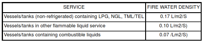
10.12 Estimation of Coverage Densities
10.12.1 The fire water demand shall be based upon densities applied over the “protected area” defined
below. The following fire water densities shall be used:
10.12.2 The minimum protected area for spheres and spheres shall be the surface area above the
maximum diameter of the vessel or tank.
10.12.3 Where the liquid level under normal operating conditions of spheres and spheroids is below the
maximum diameter of the vessel or tank, the protected area shall include the surface area between the top
of the vessel or tank and the normal liquid level.
10.12.5 Where the normal liquid level of spheres is below the maximum diameter of the vessel, a ring of
water sprays shall be added to protect the area of the shell that is not wetted by the deluge system due to
interference by the legs.
10.12.6 The minimum protected area for hemispheroids and dome-roof tanks shall be the roof area.
10.12.7 Where the tank walls exceed 23 m in height, the protected area shall include the roof and the
surface area between the roof and the mid-point of the tank walls.
10.13 Layout of Deluge Heads
The layout of deluge heads shall, ensure a uniform coverage of the protected area, irrespective of vessel
or tank appurtenances. The following shall be noted in achieving this:
10.13.1 The use of a single deluge head and overflow weir to achieve coverage is permitted only for
spheres of 13.7 m diameter and less, and spheroids, hemispheres, and dome-roof tanks of 16.8 m
diameter and less.
10.13.2 A preferred method of installation is for a ring header with multiple deluge heads to be constructed
around the main concentration of appurtenances on top of the vessel or tank.
10.13.3 A deflector plate shall be mounted around the roof-to-wall seams for hemispheroids and domed
roof tanks to direct runoff from the roof to the walls.
10.13.4 For tanks requiring more than 130 L/s, multiple heads, up to a maximum of four (4), shall be
installed. Where multiple heads are provided, they shall be spaced on a 6 m radius circle around the
center of the dome.
10.13.5 To reduce large cooling water demands, systems with over 250 L/s demand shall be arranged to
divide the flow into quadrants, so that water flow is directed to deluge heads on a tank’s exposed quadrant only. This can require individual supply feeders to each deluge head or pair of heads, depending on
exposure potential from adjacent tanks.
11. Halon 1211 and 1301 Fire Extinguishing Systems
The selection, design, and use of fixed Halon 1211 and Halon 1301 extinguishing systems shall be in
accordance with NFPA 12A,, and NFPA 12B. An acceptance test, including measurement of vapor
concentrations during and after discharge shall be conducted in accordance with OSHA, Subpart L,
1910.161.
12. Automatic Fire Detection Systems
The selection, design, and use of automatic fire detection systems (detecting heat, smoke, or flame) shall
be in accordance with NFPA 72E, and OSHA, Subpart L, 1910.164.
13. Computer and Data Processing Installations
Protection of computer installations shall be in accordance with NFPA 75.
14. Fire Alarm Systems
Fire alarm systems shall meet the design requirements of NFPA 72A, NFPA 72C, and NFPA 72D, and
OSHA, Subpart L, 1910.165.
Discover more from PAKTECHPOINT
Subscribe to get the latest posts sent to your email.