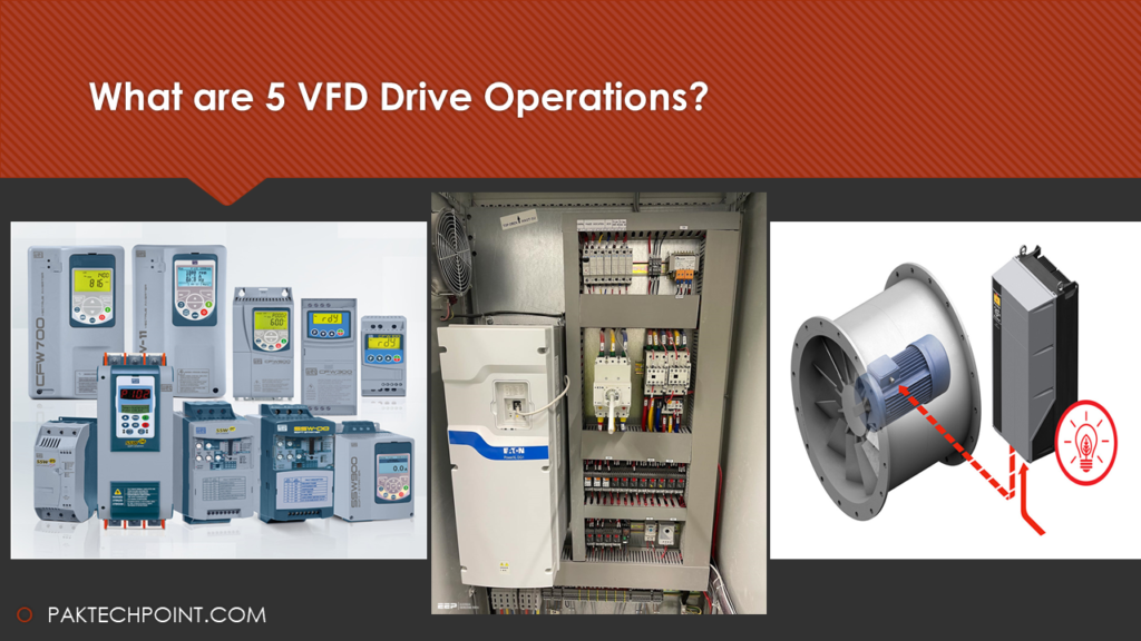
The operation of a Variable Frequency Drive (VFD) involves several key aspects that contribute to its effective performance and troubleshooting. Let’s delve into five important VFD drive operations: fault finding calculation, start-up procedure, positioning control, speed control, and troubleshooting tips.
To Read Full Technical Guide of VFD at paktechpoint.com.
1. VFD Fault-Finding Calculation:
Identifying faulty components within a VFD can be achieved through a VFD fault calculation formula. The magnitude of the VFD drive’s voltage-to-frequency (v/f) ratio is directly proportional to its v/f magnitude. This formula enables the determination of the v/f relationship at any given speed. In this context, let’s define variables: X represents the input voltage, Y denotes the output voltage, and Z signifies the load current.
2. VFD Start-Up Procedure:
Initiating a VFD involves a systematic start-up procedure to ensure proper functionality. This includes:
a. Power On: Apply power to the VFD while ensuring all safety precautions are observed.
b. Configuration: Set the desired operational parameters such as motor specifications, control mode, speed reference, and acceleration/deceleration times.
c. Start Command: Initiate the start command through external inputs or control panel.
d. Monitoring: Observe the motor’s response to ensure smooth acceleration and proper operation.
e. Adjustments: Fine-tune parameters if necessary to optimize performance.
3. VFD Positioning Control:
Positioning control with a VFD involves precise control over the motor’s position. This is commonly used in applications like conveyor systems, robotics, and CNC machines. The VFD can control the motor’s speed and direction to accurately position the load. This requires encoder or resolver feedback to provide position information to the VFD’s control system.
4. VFD Speed Control:
One of the primary functions of a VFD is to control the speed of an AC motor. This is achieved through adjusting the frequency and voltage supplied to the motor. By changing the frequency, the motor’s speed can be precisely controlled. This is particularly useful in applications that require variable speed operation to match varying load conditions.
5. VFD Troubleshooting Tips:
Troubleshooting VFD issues requires a systematic approach:
a. Check Connections: Verify all wiring connections and ensure they are properly tightened.
b. Parameter Check: Review the configured parameters for accuracy and compatibility with the motor specifications.
c. Overcurrent Protection: Investigate if overcurrent protection mechanisms are triggering due to excessive load.
d. Motor Temperature: Monitor the motor’s temperature to avoid overheating issues.
e. Error Codes: Understand and interpret error codes displayed on the VFD’s control panel or interface.
f. Noise and Interference: Address issues related to electrical noise and interference that can affect VFD performance.
g. Grounding: Ensure proper grounding to prevent electrical noise and protect against voltage spikes.
h. Software Updates: Keep the VFD’s firmware and software up-to-date to benefit from bug fixes and enhancements.
VFD operations encompass a range of functionalities from accurate fault detection to precise speed and positioning control. Following proper start-up procedures, understanding fault-finding calculations, and effective troubleshooting are crucial for maintaining optimal VFD performance and extending its lifespan.
VFD Inverter Configuration and Components
VFD INVERTER CONFIGURATION AND COMPONENTS
A VFD inverter plays a pivotal role in the conversion of input power into a three-phase output AC, effectively controlling motor speed and performance. Understanding the configuration and components of a VFD inverter is crucial for its effective operation in various applications.
VFD Inverter Configuration:
The core purpose of a VFD inverter is to take incoming power and convert it into a controlled AC output. The configuration of a VFD inverter varies based on the required performance and efficiency. There are primarily two configurations:
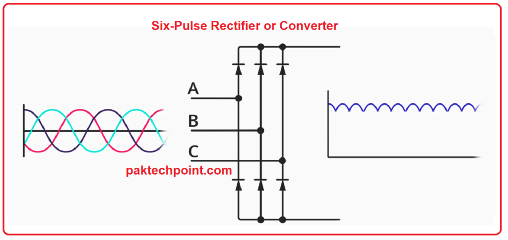
- 6-Pulse V/F Configuration: This configuration utilizes six IGBTs (integrated gate bipolar transistors) as its power devices. These IGBTs are strategically arranged to create a 6-pulse V/F configuration. This setup ensures efficient and controlled power conversion from the input to the output.
- 12-Pulse V/F Configuration: For enhanced performance, a 12-pulse V/F configuration is employed. This involves the utilization of twelve power devices, often a combination of IGBTs and thyristors. The complexity of the 12-pulse configuration allows for improved power quality and reduced harmonic distortion.
VFD Inverter Components:
A VFD inverter comprises three essential components: input, output, and control terminals. Each of these components contributes to the seamless operation of the VFD system.
- Input Terminals: The input terminals are responsible for receiving the incoming power supply. They are connected to the source of power, often a DC bus, and play a crucial role in initiating the power conversion process.
- Output Terminals: The output terminals are connected to the motor that the VFD inverter drives. These terminals supply the controlled AC output generated by the inverter to the motor, thereby controlling its speed and performance.
- Control Terminals: The control terminals are essential for managing and regulating the entire VFD system. They connect to the control panel or interface that allows operators to set parameters such as speed, acceleration, deceleration, and other operational settings.
Power Devices in VFD Inverter:
The power devices within a VFD inverter play a significant role in its operation. The most common power devices used are:
- IGBTs (Insulated-Gate Bipolar Transistors): IGBTs are integral to the switching mechanism of a VFD inverter. They act as electronic switches that control the flow of current from the input to the output, ensuring smooth power conversion.
- Thyristors: Thyristors, also known as silicon controlled rectifiers (SCRs), are used in some configurations of VFD inverters. They are responsible for rectification and controlled flow of current, contributing to efficient power conversion.
Function of VFD Inverter:
The primary function of a VFD inverter is to transform low-voltage DC input into an AC output with a specific voltage-to-frequency (V/F) ratio. This conversion is instrumental in controlling the speed and performance of AC motors. By adjusting the V/F ratio, operators can effectively regulate the motor’s speed. Increasing the V/F ratio enhances the motor’s speed, making it a crucial parameter for achieving desired motor performance.
In summary, the VFD inverter configuration encompasses the arrangement of power devices based on the desired performance level, while its components, including input, output, and control terminals, contribute to its operational functionality. The power devices within the inverter, such as IGBTs and thyristors, play a key role in power conversion. Ultimately, the VFD inverter’s ability to convert low-voltage DC into controlled AC output with adjustable V/F ratio empowers precise control over motor speed and performance in various applications.