Accelerometers work based on the principle of inertia. They contain small masses suspended within the sensor, and when the device experiences acceleration, these masses move in response to the force applied. The movement of these masses is measured, and based on that, the acceleration is calculated.
What is Accelerometer?
Components & Working Principle.
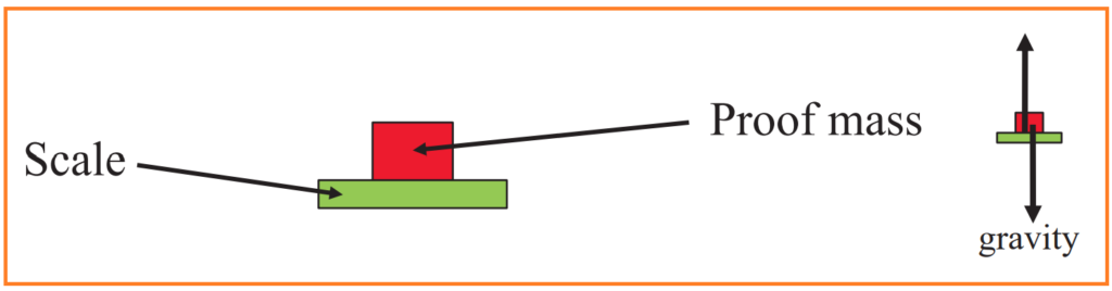
The accelerometer consists of a proof mass glued to a scale capable of measuring both positive (push) and negative (pull) weights. This setup allows the accelerometer to detect both acceleration and deceleration.
Accelerometers typically measure “specific force,” which is the force per unit mass (expressed in m/s²). Specific force includes:
- Acceleration specific force: Represents the linear acceleration experienced by the accelerometer, denoted as “a” in units of m/s².
- Gravitational specific force: Approximately equal to 9.8 m/s², representing the acceleration due to gravity experienced by the accelerometer when at rest on the Earth’s surface.
When the accelerometer (scale) is at rest on the floor, the output of the accelerometer will be positive and approximately equal to the acceleration due to gravity, denoted as “+g” and approximately equal to 9.8 m/s². This is because the accelerometer is experiencing the gravitational force pulling it towards the Earth’s surface.
If the accelerometer is in “free fall,” meaning it is in a state of unimpeded descent under the influence of gravity alone, there is no external force acting on the scale. Consequently, the output of the accelerometer will be zero (0 m/s²). This is because there are no forces acting on the scale other than gravity, which is already accounted for as the baseline reading.
Types of Accelerometer.
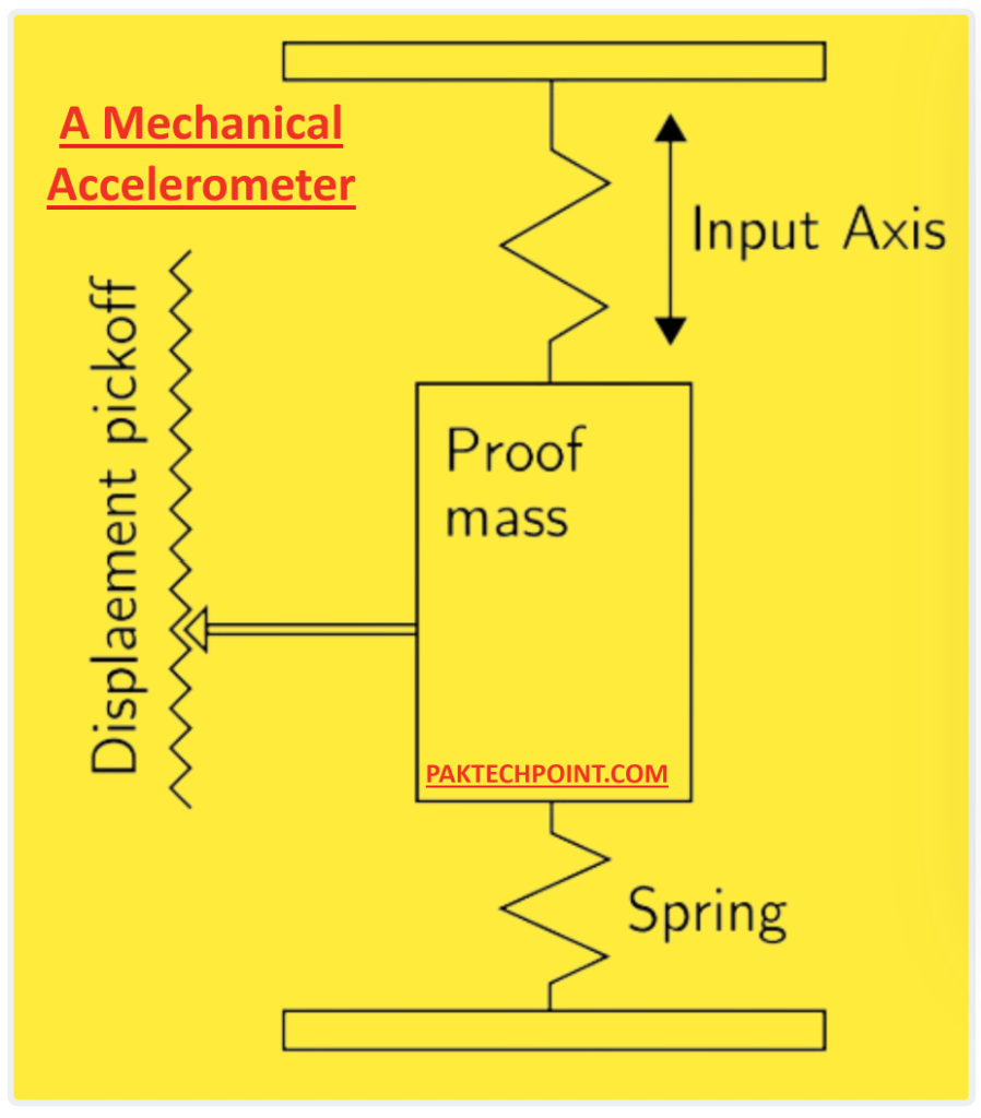
1. Mechanical Accelerometer.
A mechanical accelerometer operates with a setup comprising a mass suspended by springs, as depicted in Figure Above. The displacement of this mass is tracked using a displacement pick-off, which generates a signal corresponding to the force F applied to the mass along the input axis. By employing Newton’s second law (F = ma), the device can determine the acceleration it experiences.
2. Solid State Accelerometers.
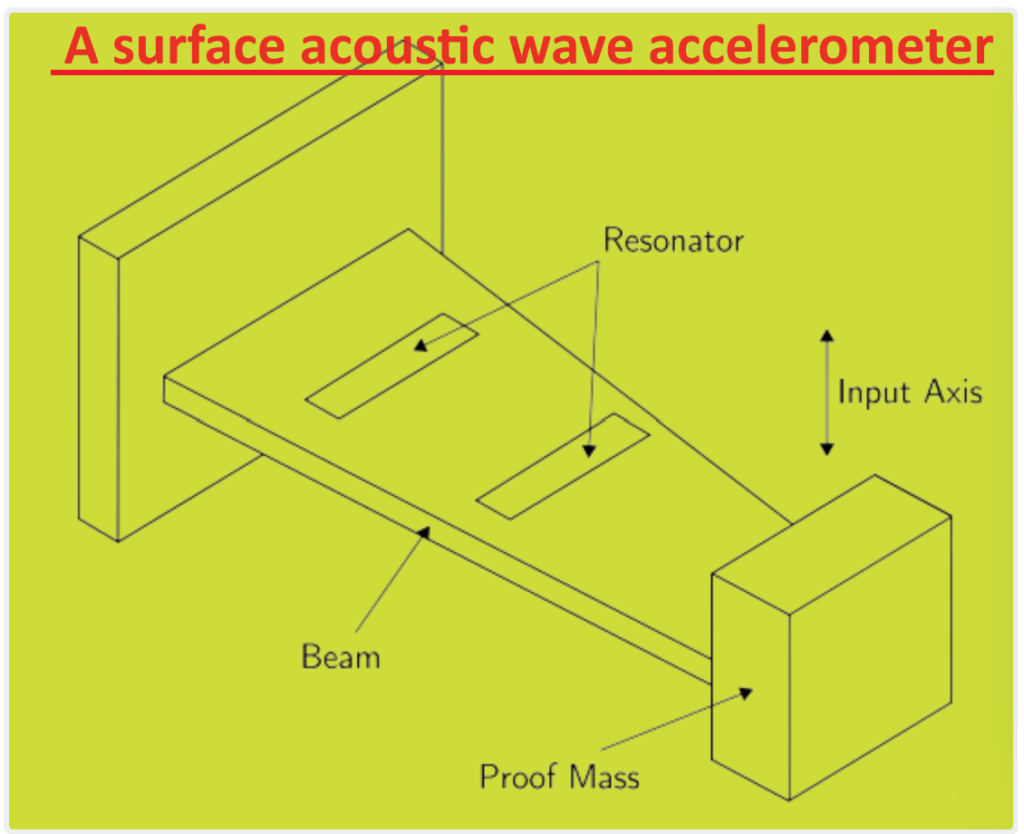
Solid-state accelerometers come in various types, including surface acoustic wave (SAW), vibratory, silicon, and quartz devices. They are known for their small size, reliability, and durability.
For instance, a SAW accelerometer operates with a cantilever beam that vibrates at a specific frequency, as illustrated in Figure below. One end of the beam holds a mass that can move freely, while the other end is firmly attached to the device’s case. When an acceleration is applied along the input axis, the beam bends, altering the frequency of the surface acoustic wave in proportion to the strain. By measuring this frequency change, the accelerometer can determine the applied acceleration.
3. MEMS accelerometers.
MEMS accelerometers operate on the same principles as mechanical and solid-state sensors but are manufactured using micro-machining techniques. There are two main types of MEMS accelerometers:
- Mechanical MEMS accelerometers: These devices measure the displacement of a supported mass and are produced using MEMS techniques.
- Frequency-based MEMS accelerometers: These devices measure the change in frequency of a vibrating element due to a change in tension, similar to SAW accelerometers.
Like MEMS gyroscopes, MEMS accelerometers offer advantages such as small size, light weight, low power consumption, and quick start-up times. However, their accuracy currently lags behind that of accelerometers made using traditional techniques. Nonetheless, the performance of MEMS devices is improving rapidly over time.
Accelerometer Technologies.
Accelerometers come in different types, each using unique technologies to measure forces. Here are some common ones:
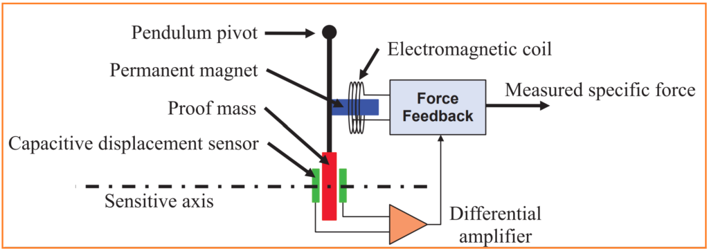
- Force-Feedback Pendulum:
- This type of accelerometer uses a pendulum mechanism. The force acting on the proof mass causes the pendulum to move, and the accelerometer measures this movement to determine the force applied. It’s like watching how much a pendulum swings to figure out the force acting on it.
- Vibrating Beam (or Dual Vibrating Beam):
- These accelerometers utilize beams that vibrate when forces are applied. The vibration patterns change based on the forces acting on the accelerometer, allowing it to measure those forces. It’s similar to how a guitar string vibrates when plucked, and you can tell how hard it was plucked by how much it vibrates.
- Micro-Machined with Electrostatic Control of Proof Mass:
- This type of accelerometer involves tiny mechanical structures (micro-machined) with a proof mass that can move. Electrostatic forces are used to control the movement of the proof mass. By measuring the electrical signals needed to keep the proof mass in place, the accelerometer can determine the forces acting on it. It’s like using electricity to control and measure the movement of a tiny weight.
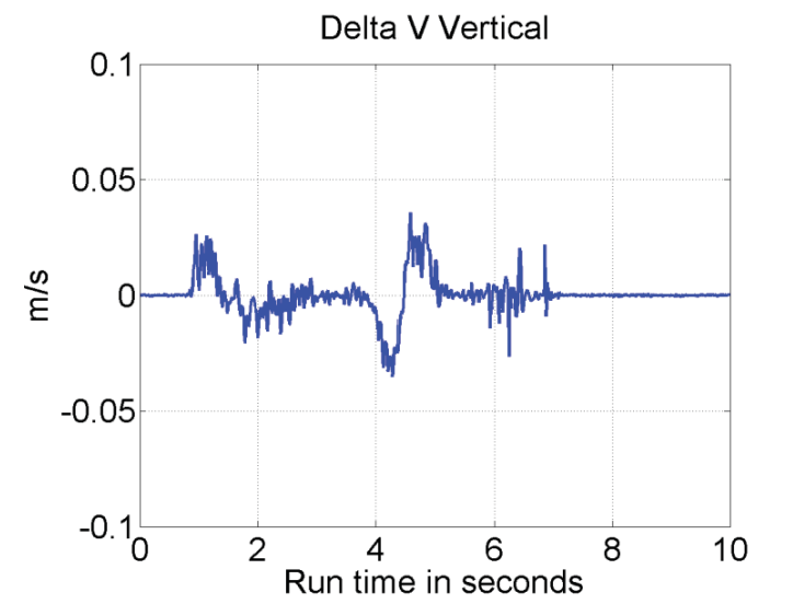
Delta Velocity instead of Acceleration.
Instead of measuring acceleration directly, some systems use delta velocity (ΔV) to understand changes in velocity over time. Delta velocity refers to the change in velocity of an object over a certain period. This approach provides insights into how an object’s speed is changing rather than its rate of acceleration.
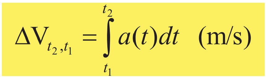
Delta velocity (ΔV) represents how much an object’s speed changes over a specific period, from one time (t1) to another (t2). For most situations, a time interval (delta t) of 0.01 seconds is typically sufficient. However, in high-speed scenarios, such as fast-moving vehicles or spacecraft, smaller time intervals as short as 0.00025 seconds may be used for more precise measurements.
When an accelerometer measures the force of gravity, the acceleration (a) is approximately 9.8 meters per second squared (m/s²). For a time interval of 0.01 seconds, this translates to a change in velocity (delta V) of around 0.098 meters per second (m/s). This format is convenient because it simplifies the subsequent processing of data. Some sensors are designed to directly measure this change in velocity, which helps reduce the amount of data collected and the range of values that need to be handled compared to implementing a single integration process outside the sensor.
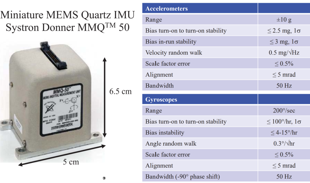
Example Inertial Measurement Unit.
An Inertial Measurement Unit (IMU) is a device commonly used in various applications, from aerospace and robotics to automotive and consumer electronics.
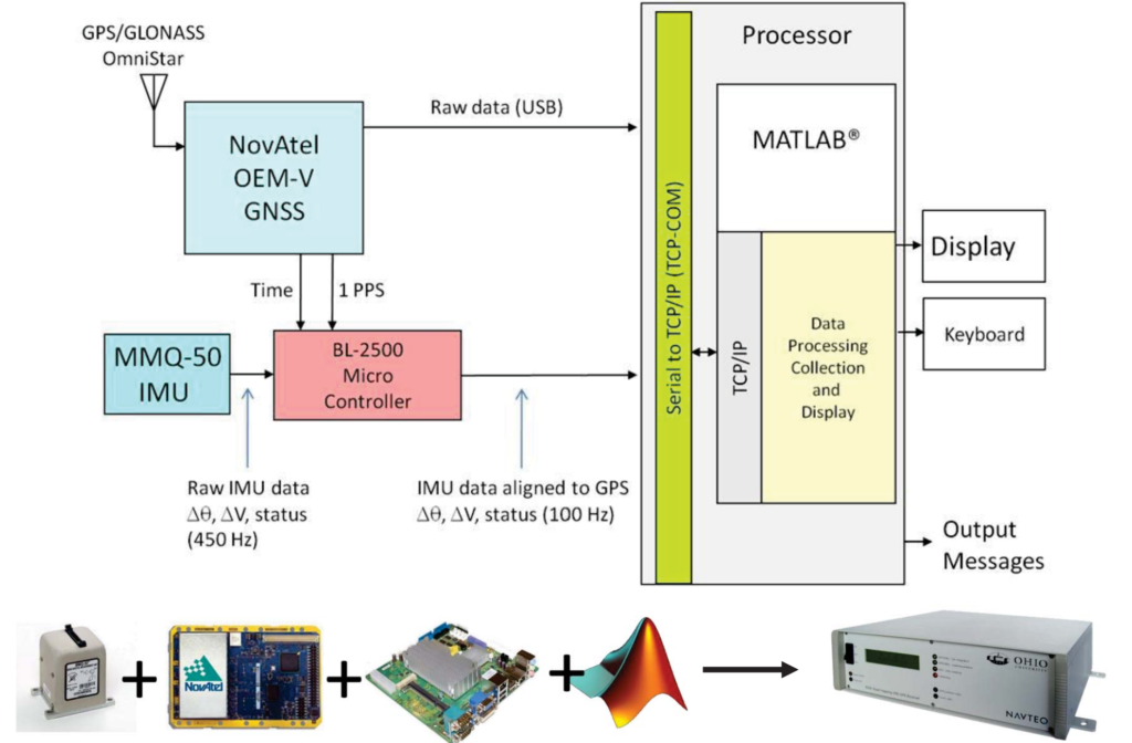
Hardware Integration Research Platform.
A Hardware Integration Research Platform is a specialized system designed to facilitate research and development activities that involve integrating various hardware components and technologies.
Inertial Navigation in the Vertical Direction.
Inertial navigation in the vertical direction refers to the use of inertial sensors to determine changes in altitude or vertical position. While traditional inertial navigation systems primarily focus on horizontal movement (e.g., forward/backward and left/right), vertical navigation involves tracking changes in elevation, ascent, or descent.
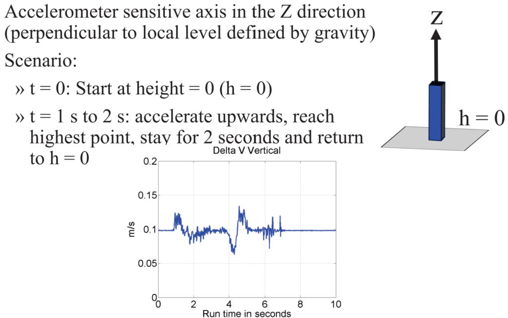
MEMS Accelerometer: Vertical Acceleration.
MEMS accelerometer measuring vertical acceleration, several assumptions are made to simplify the analysis:
- Assumption of Minimal Errors: It is assumed that the accelerometer has negligible errors, except for the presence of noise in its measurements. This simplifies the analysis by considering only the effects of noise on the accelerometer’s output.
- Uniform Gravity: It is assumed that the gravitational acceleration remains constant regardless of changes in height or altitude. This assumption simplifies the calculation by treating gravity as a constant value throughout the measurement period.
To estimate the effect of gravity on the accelerometer’s measurements and remove it from the measured vertical acceleration (‘V’), a technique called “zero-velocity update” (ZUPT) is employed. In this technique, the first second of data is utilized to estimate the gravitational acceleration, which is then subtracted from the measured acceleration to eliminate its influence. Here’s how it works:
- Estimation of Gravity:
- During the first second of data collection, the accelerometer registers both the effect of gravity and any additional acceleration due to motion or noise.
- By averaging the accelerometer readings over this period, an estimate of the gravitational acceleration can be obtained. This average value represents the gravitational component of the accelerometer’s output.
- Subtraction of Gravity:
- Once the gravitational acceleration is estimated, it is subtracted from the measured vertical acceleration (‘V’) for the entire duration of data collection.
- This subtraction effectively removes the gravitational component from the accelerometer’s measurements, leaving behind only the acceleration due to motion or noise.
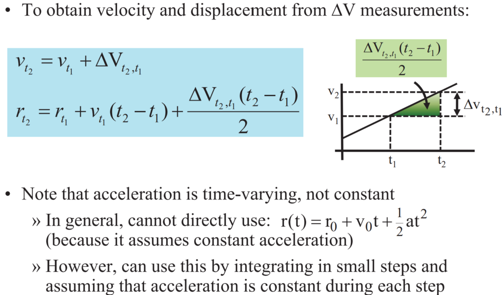
Vertical Velocity and Displacement.
When dealing with vertical motion, understanding vertical velocity and displacement is crucial for navigation, analysis, and various applications.
Measured Vertical Velocity and Displacement.
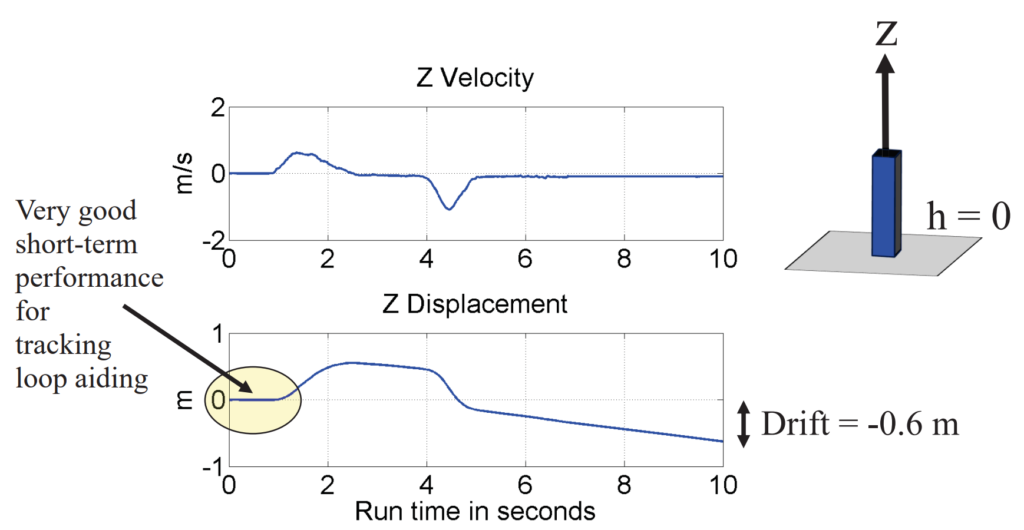
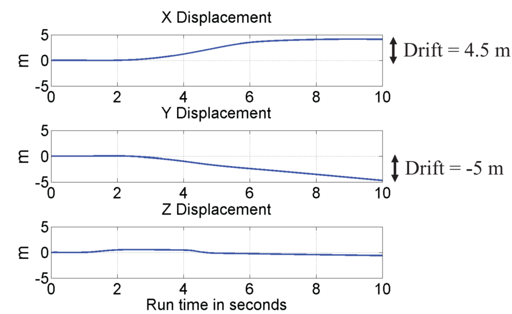
What Happened in the X and Y Directions?
To understand what happened in the X and Y directions, we need to consider the motion or changes that occurred along these axes. The X and Y directions typically represent horizontal movements or displacements in a two-dimensional coordinate system.
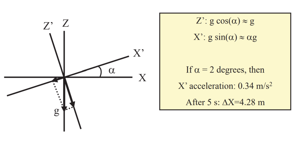
Leveling Error.
A leveling error refers to a discrepancy or inaccuracy in the leveling process, particularly when attempting to establish a level reference plane or surface. Leveling is the process of determining the horizontal or vertical orientation of a surface relative to gravity or a specified reference point.