A gyroscope is a device used to measure or maintain orientation and angular velocity. It works based on the principle of angular momentum, where a spinning rotor maintains its orientation in space regardless of external forces acting upon it.
Gyroscope Components:
- Rotor: The central component of a gyroscope is a spinning rotor. This rotor is typically mounted on a set of gimbals, allowing it to rotate freely in multiple axes.
- Gimbal System: The rotor assembly is often housed within a gimbal system, which provides support and allows the rotor to rotate in different directions while maintaining its orientation.
Principle of Operation:
When the rotor of a gyroscope spins, it generates angular momentum perpendicular to its axis of rotation. According to the law of conservation of angular momentum, this momentum remains constant unless acted upon by an external torque.
As a result, when the gyroscope is subjected to external forces that attempt to change its orientation, the gyroscopic effect causes the rotor to resist this change and maintain its original orientation in space.
Gyroscopes can be used in various applications to measure or detect changes in orientation or angular velocity. For example, they are used in inertial navigation systems, spacecraft orientation control, stabilization of cameras and drones, and navigation aids in vehicles.
Types of Gyroscope
1. Mechanical Gyroscopes
A regular gyroscope has a spinning wheel that can move in all directions thanks to two gimbals it’s mounted on. This setup is shown in Figure below. Because of a rule called the conservation of angular momentum, the spinning wheel resists changing its direction. So, when you move or rotate the gyroscope, the spinning wheel stays pointing in the same direction, but the angles between the gimbals change. To find out which way the gyroscope is pointing, we can measure these angles using special sensors called angle pick-offs. It’s important to note that a regular gyroscope measures the direction something is facing.

Nowadays, most gyroscopes, like the optical and MEMS types mentioned earlier, actually measure how fast something is rotating. These are called rate-gyroscopes.
One problem with regular gyroscopes is that they have parts that move. This movement creates friction, which can make the readings less accurate over time. To reduce this friction, we use really precise bearings and special oils, but this makes the gyroscope more expensive. Also, regular gyroscopes need a few minutes to get warmed up before they work properly, which isn’t great in some situations.
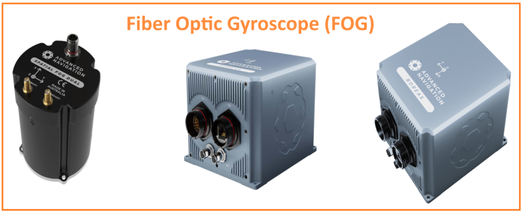
2. Fiber Optic Gyroscope (FOG)
A fiber optic gyroscope (FOG) uses light interference to measure how fast something is rotating. It has a big coil of optical fiber. To measure rotation, two beams of light are sent into the coil, going in opposite directions. If the sensor is spinning, the beam going in the direction of the spin will take a longer path through the fiber than the one going against it. This is called the Sagnac effect. When the beams come out of the fiber, they are mixed together. The difference in their paths causes them to interfere, and the combined beam’s brightness changes depending on how fast the sensor is spinning. By measuring this brightness, we can figure out the rotation speed.
A gyroscope is a device that uses the principle of angular momentum to measure or maintain orientation and angular velocity. It finds wide-ranging applications in navigation, stabilization, and control systems across various industries and technologies.
Ring laser gyroscopes (RLGs) work similarly, also using the Sagnac effect. But instead of fiber optic coils, RLGs use mirrors to guide laser beams in a closed loop.
Unlike regular gyroscopes with moving parts, optical gyros like FOGs and RLGs don’t have any moving pieces. They only take a few seconds to start working properly. The accuracy of an optical gyro mainly depends on how long the light travels inside it – the longer, the better. But the size of the device limits how long the light path can be.

3. MEMS Gyroscopes
MEMS gyroscopes have emerged as a cost effective alternative to traditional mechanical and optical gyroscopes due to their simplicity and affordability. Unlike mechanical and optical gyroscopes, which require numerous parts and intricate assembly, MEMS gyroscopes are built using silicon micro-machining techniques, resulting in low part counts (sometimes as few as three parts) and lower manufacturing costs.
MEMS gyroscopes utilize the Coriolis effect, which occurs when a mass moving with velocity experiences a force in a rotating frame of reference. This effect is harnessed by MEMS gyroscopes through vibrating elements, such as vibrating wheels or tuning forks. In the simplest form, a single mass vibrates along a drive axis, and when the gyroscope rotates, a secondary vibration perpendicular to the drive axis is induced due to the Coriolis force. By measuring this secondary vibration, the gyroscope can determine the angular velocity.

While MEMS gyroscopes currently lag behind optical devices in terms of accuracy, they offer several advantages:
- Small size and low weight.
- Robust construction.
- Low power consumption.
- Quick start-up time.
- Cost-effectiveness in high-volume production.
- High reliability and low maintenance.
- Compatibility with harsh environments.
However, the main drawback of MEMS gyroscopes is their lower accuracy compared to optical devices. A comparison between two gyroscopes manufactured by Honeywell illustrates this difference. The GG1320AN is a single-axis digital laser gyro, while the GG5300 is a three-axis MEMS rate gyro. Although the MEMS package contains three gyroscopes instead of one, and offers benefits like lower power consumption and quicker start-up time, it is less accurate, as indicated by bias stability and angular random walk measurements.
Specifications for the Honeywell GG1320AN and GG5300 gyroscopes

MEMS Gyro Error Characteristics
MEMS gyroscopes, like other sensors, have certain error characteristics that affect their accuracy. Let’s explore these characteristics:
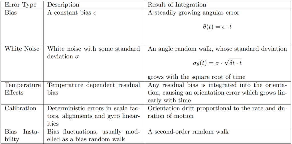
1. Constant Bias:
The bias of a gyro is the average output when it’s not rotating, which is the offset from the true value, measured in degrees per hour (°/h). Constant bias causes a linear increase in angular error over time. To correct for this, we can measure the bias when the gyro is stationary and subtract it from the output.
2. Thermo-Mechanical White Noise / Angle Random Walk:
MEMS gyro outputs can be disturbed by thermo-mechanical noise, resulting in a white noise sequence with zero-mean random variables. Integrating this noise over time creates a random walk error in the output, with the standard deviation growing proportional to the square root of time. Manufacturers often specify this noise using an angle random walk (ARW) measurement in degrees per root hour (°/√h).
3. Flicker Noise / Bias Stability:
Flicker noise causes the gyro bias to fluctuate over time, typically observed at low frequencies. Bias stability describes how much the bias may change over a specified period under fixed conditions. It’s often specified in degrees per hour (°/h) or degrees per second (°/s). Bias fluctuations are usually modeled as a random walk, with the standard deviation growing proportional to the square root of time.
4. Temperature Effects:
Temperature changes can induce movement in the gyro bias, causing errors in orientation that increase linearly with time. This relationship can be highly nonlinear for MEMS sensors. Internal temperature sensors in inertial measurement units (IMUs) help correct for temperature-induced bias effects.
5. Calibration Errors:
Calibration errors refer to errors in scale factors, alignments, and linearities of the gyros. These errors produce bias errors observed during motion, leading to additional drift in the integrated signal. Calibration errors can be measured and corrected, often internally in modern IMUs.
Understanding and accounting for these error characteristics is crucial for ensuring the accuracy and reliability of MEMS gyroscopes in various applications.
Applications:
- Navigation: Gyroscopes are used in navigation systems to measure changes in orientation and angular velocity. They provide essential data for determining the orientation of aircraft, spacecraft, ships, and vehicles.
- Stabilization: Gyroscopes are used to stabilize platforms, cameras, telescopes, and other devices by counteracting unwanted movements or vibrations.
- Control Systems: Gyroscopes are integral components of control systems in robotics, drones, and industrial machinery, helping maintain stability and precise control over movements.
What is Sagnac effect?
The effect occurs when a beam of light is split into two beams traveling in opposite directions along a closed loop, typically in the form of a ring interferometer. When the entire apparatus is rotated, the beams of light experience different path lengths due to the rotation of the apparatus itself. As a result, when the beams are recombined, they interfere with each other, causing a measurable phase shift. This phase shift is directly proportional to the angular velocity of the rotation and the area enclosed by the light path.