What is Aircraft Jet Engine?
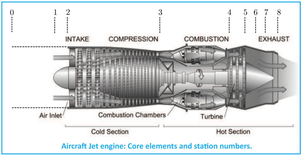
Jet engines, also known as gas turbine engines, consist of several core elements or components that are common across various types of engines. These core elements are typically organized into canonical engine station numbers, which represent different points along the airflow path through the engine. The main elements include the inlet, compressor, burner (combustor), turbine, afterburner (if equipped), and nozzle.
In a jet engine, the inlet is responsible for bringing in freestream air into the engine, while the compressor increases the pressure of the incoming air. The compressed air then enters the burner, where fuel is injected and mixed with high-pressure air before being ignited and burned. The resulting high-temperature exhaust gases flow through the turbine, where they expand and generate mechanical work to drive the compressor and any other necessary components. Finally, the exhaust gases exit the engine through a nozzle, where they are accelerated to produce thrust according to Newton’s action-reaction principle.
These core elements and their functions are essential components of jet engine operation, enabling the conversion of fuel into thrust to propel the aircraft forward. Each element plays a critical role in the overall performance and efficiency of the engine, making them fundamental to the operation of jet-powered aircraft.
Thermodynamics Role in Jet Engine
Thermodynamics forms the basis for understanding the operation of jet engines. The first law of thermodynamics, expressed as ΔE=Q+W, states that the change in energy of a system (ΔE) is equal to the heat added to the system (Q) plus the work done by the system (W). In the context of a jet engine, this law relates the change in internal energy, heat transfer, and work done during the engine’s operation.
The energy of a system can be divided into internal energy (U), kinetic energy (mV2/2), and potential energy (mgz). For a jet engine, where altitude (z) remains relatively constant and kinetic energy can be neglected, the energy equation simplifies to ΔU=Q+W. Here, work (W) consists of mechanical work (Wmech) and work associated with changes in gas volume (Δ(PV)).
Enthalpy (ℎ) is defined as the sum of internal energy and pressure-volume work (PV). The energy equation can also be expressed in terms of enthalpy change (Δℎ), which is related to the change in temperature (ΔT) through the specific heat of the gas (c). Additionally, stagnation values of properties, denoted by subscript “t” (e.g., ℎt), are related to real values by accounting for kinetic energy, such as
Aircraft Jet Engine Components
1. Inlet
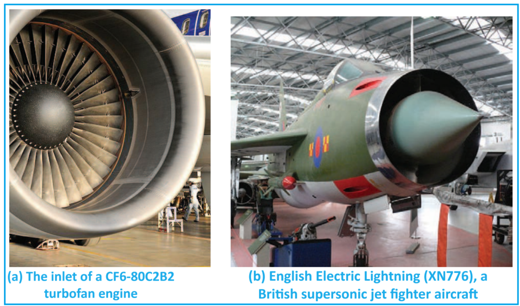
The inlet, also known as the intake, is the entry point through which free-stream air enters the jet engine. The design of the inlet varies depending on the speed regime of the aircraft. For subsonic aircraft, such as most commercial airliners, the inlet design is typically simple and short, with a thick inlet lip. In contrast, supersonic aircraft inlets have a sharper lip to minimize performance losses from shock waves at supersonic speeds. This design helps slow down the airflow to subsonic speeds before it reaches the compressor.
Efficient operation of the inlet is crucial under all flight conditions, from low to high speeds. At low speeds, the inlet must effectively draw air into the engine to maintain proper engine function. At high speeds, it must allow for maneuverability without disrupting airflow to the compressor. Although the inlet does not perform thermodynamic work, it plays a critical role in maintaining a constant total temperature through the inlet, ensuring optimal engine performance.
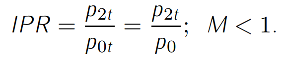
The total pressure through the inlet is subject to changes caused by aerodynamic flow effects. This change is often quantified by the inlet pressure recovery (IPR), which indicates the extent to which the free-stream flow conditions are restored. Mathematically, the inlet pressure recovery (IPR) can be expressed as follows:
Achieving a high pressure recovery in the inlet is crucial for engine efficiency. The shape of the inlet, the aircraft’s speed, the airflow characteristics required by the engine, and aircraft maneuvers all play significant roles in achieving this goal. The efficiency of the inlet, which is closely linked to pressure recovery, can be expressed as:

2. Compressor
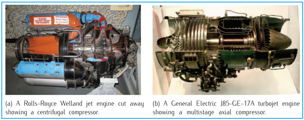
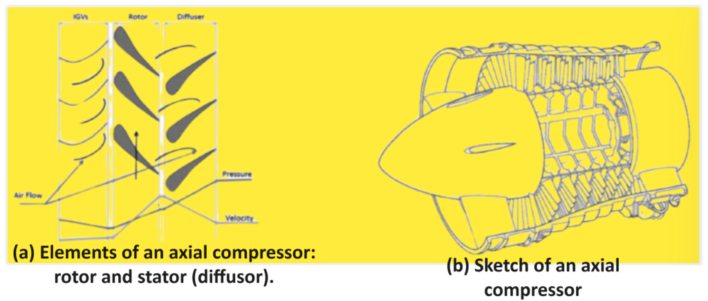
The compressor plays a vital role in increasing the pressure of the incoming air through mechanical work. There are two primary types of compressors used in jet engines: axial and centrifugal. In axial compressors, airflow moves parallel to the rotation axis, while in centrifugal compressors, airflow moves perpendicular to the axis of rotation. While centrifugal compressors were used in early jet engines and are still employed in small turbojets, modern turbojets and turbofans typically utilize axial compressors.
An axial compressor consists of alternating rotor-stator pairs, where the rotor increases the absolute velocity of the fluid, and the stator converts this into pressure increase. In comparison, a single-stage centrifugal compressor typically increases airflow pressure by a factor of 4, whereas a single-stage axial compressor achieves pressure increases ranging from 15% to 60%. However, axial compressors offer the advantage of easily linking multiple stages together to form multistage compressors capable of achieving higher pressure ratios, up to 40. While producing an efficient multistage centrifugal compressor is challenging, axial compressors are favored in most high-compression jet engines due to their ability to deliver significant compression efficiently. However, for applications requiring moderate compression, centrifugal compressors may be a suitable choice.
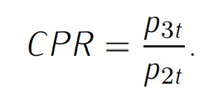
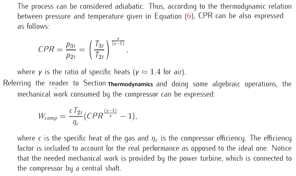
The pressure increase across the compressor is quantified by the compressor pressure ratio (CPR), defined as the ratio between the stagnation pressure at stage 3 (p3t) and the stagnation pressure at stage 2 (p2t). Using the station numbers illustrated in Figure 1, the compressor pressure ratio (CPR) can be mathematically expressed as:
3. Combustion chamber
The combustion chamber, also known as the burner, is where fuel is mixed with high-pressure air from the compressor and ignited. This combustion generates high-temperature exhaust gases, which then power the turbine, producing mechanical work to drive the compressor and create thrust when expelled through the nozzle.
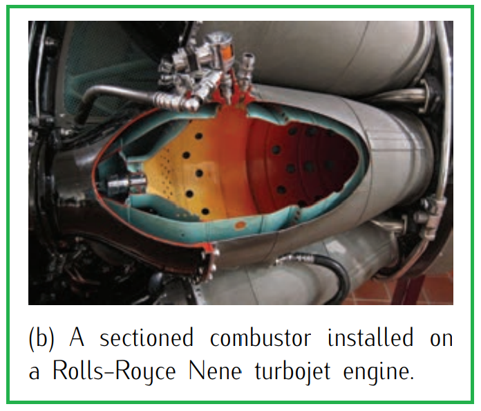
There are three main types of combustion chambers: annular, can, and hybrid can-annular. Can combustors consist of individual cylindrical chambers with their own fuel injectors and air sources. Can-annular combustors have separate combustion zones contained within individual liners but share a common air casing. Annular combustors have a continuous ring-shaped liner and casing.
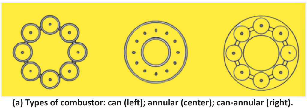
Modern gas turbines may incorporate any of these designs, with annular designs being more common due to their simplicity and efficiency. In these chambers, the air temperature increases while the pressure remains nearly constant. The pressure ratio within the combustor, known as the combustor pressure ratio (CPR), is determined by the stagnation pressures at specific stages within the engine.

In the combustion chamber, thermodynamics differ from those in the compressor and turbine because heat is released during the combustion process. While the compressor and turbine operate adiabatically (without heat exchange), the combustion chamber involves the addition of fuel. This introduces a non-adiabatic process, where fuel is mixed with air and ignited to release heat.
To account for the added fuel mass, a ratio ( f ) is used to quantify the fuel flow relative to the air mass flow. This ratio represents the proportion of fuel being introduced into the combustion chamber compared to the mass of air passing through it.
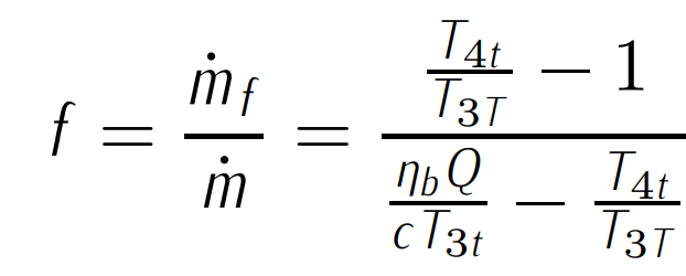
In the equation, represents the mass flow rate of fuel, is the heating constant (which varies depending on the type of fuel being used), denotes the average specific heat, is the stagnation temperature at the entrance of the combustion chamber, is the stagnation temperature at the exit of the combustion chamber, and is the efficiency of the combustion chamber. This ratio is crucial for understanding overall aircraft performance because it indicates the amount of fuel required to combust a given quantity of airflow (under specific pressure and temperature conditions downstream of the compressor), consequently generating the corresponding thrust.
4. Turbine
The turbine, positioned downstream of the combustor, converts the thermal energy from the hot airflow into mechanical work to drive the compressor. This conversion is facilitated by two rows of blades within the turbine: the rotor, which rotates at high speeds, and the stator, which remains stationary. Operating within temperatures of approximately 1400°K, these blades are typically crafted from specialized metals, such as titanium alloys, capable of withstanding such heat.
Engine configurations vary, with turbofan and turboprop engines often employing separate turbines and shafts to power the fan and gearbox, respectively, known as two-spool engines. Some high-performance engines feature three-spool configurations, incorporating an additional turbine and shaft to drive distinct sections of the compressor.
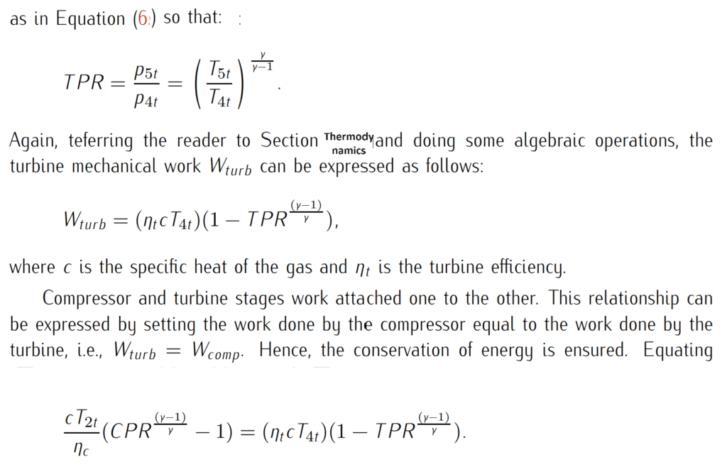
Similar to the compressor, the equations governing airflow evolution over the turbine are derived through analogous methods. As airflow traverses the turbine, both pressure and temperature diminish. The reduction in pressure is quantified by the turbine pressure ratio (TPR), defined as the ratio of exiting to entering air pressure in the turbine. Using the station numbers depicted in Figure 1 above, the TPR equates to the stagnation pressure at point 5 (p5t) divided by the stagnation pressure at point 4 (p4t).
5. Nozzles
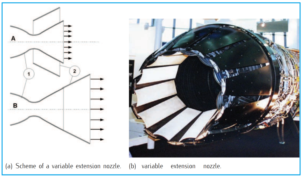
The nozzle serves as the final component of the jet engine and fulfills three primary functions: a) generating thrust, b) directing exhaust gases back to freestream conditions, and c) regulating the mass flow rate through the engine by setting the exhaust area. Positioned downstream of the turbine, the nozzle’s design varies based on aircraft performance requirements.
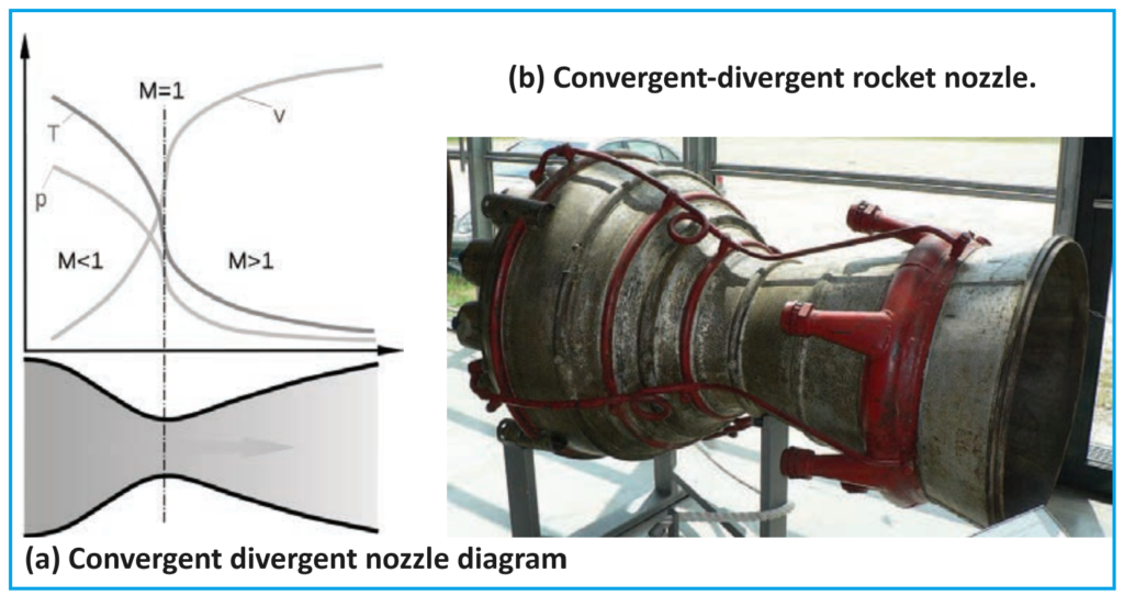
Simpler turbojets and turboprops typically feature fixed-geometry convergent nozzles. In contrast, turbofan engines may employ coannular nozzles, where core flow exits the center nozzle and fan flow exits the annular nozzle. Afterburning turbojets and certain turbofans often integrate variable-geometry convergent-divergent nozzles (also known as de Laval nozzles), which compress the flow through a convergent throat before expanding it, typically to supersonic velocities, through the divergent section.
Analyzing the equations governing flow evolution within the nozzle, it’s notable that the nozzle does not perform work on the flow. Consequently, both stagnation temperature and stagnation pressure can be considered constant. Referring to station numbers, the nozzle’s effect on flow characteristics can be quantified.