An LCR meter, which stands for Inductance (L), Capacitance (C), and Resistance (R) meter, is a specialized electronic test instrument used to measure the impedance of passive electronic components, such as resistors, capacitors, and inductors.

LCR Meter Used For.
An LCR meter is a tool used for measure the electrical properties of components and circuits. It can measure three main things: inductance (how coils store energy), capacitance (how capacitors store energy), and resistance (how materials resist the flow of electricity). It can also show other important properties like impedance, phase angle, and quality factor.
To measure these properties, the LCR meter sends a signal through the component or circuit and measures how it responds. It does this by applying a specific type of electrical signal at a certain frequency and then measuring the resulting signal. Based on this, the meter calculates the properties of the component.
Since components and circuits come in different shapes and sizes, you need special wires and connectors to connect them to the LCR meter. These wires and connectors also have their own electrical properties, which can affect the measurements. So, it’s important to adjust the measurements to account for these extra properties and get accurate results for the component being tested.
Example and Application of LCR Meter.
A 3-phase induction motor is installed to run non-stop for 24 hours, 7 days a week in industrial sectors. To ensure its reliable operation, maintenance technicians decide to understand the motor’s electrical characteristics. They use an LCR meter to measure the inductance of the motor’s three windings at a frequency close to the line frequency. By periodically measuring these windings, any changes in inductance can help diagnose potential issues, like a shorted winding, which could affect the motor’s performance.
Taking the diagnostic check further, the technician measures each winding’s inductance as the rotor angle changes. Plotting these inductance values against the rotor angle can reveal subtle issues with the motor’s overall health.
Comparing the inductance of the stator’s windings can also help in diagnosing problems, especially with multi-phase induction motors. For a new motor, the inductance of the three windings should be roughly the same. Keeping these measurements for comparison later can help troubleshoot any issues or degradation in the motor.

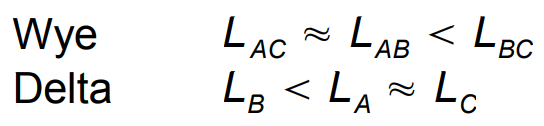
A shorted turn in a winding will have lower inductance compared to a non-shorted turn. In a wye connection, if two phase-to-phase inductances are similar but less than the third, it suggests a shorted turn. Similarly, in a delta connection, if one inductance is significantly lower than the others, it indicates a potential shorted turn. Calculating the mean inductance and examining the deviation from it can help identify any inductive imbalances.
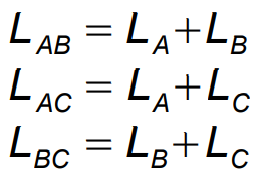
we have the following relationships for a motor with a shorted turn:
We also have the relationships for the wye connection.
Shorted turns usually occur due to insulation failure in a winding, leading to hot spots, physical damage, or manufacturing defects. These issues can compromise the motor’s performance and reliability, making it essential to identify and address them promptly.
Benefits of an LCR meter.
An LCR meter offers several benefits that make it a valuable tool for electronics testing and troubleshooting:
- Impedance Measurement: Allows you to measure the impedance of a circuit, aiding in troubleshooting and characterizing existing circuits. This helps identify issues and optimize circuit performance.
- Component Identification: Helps identify unmarked components and sort components into bins with specified tolerances, facilitating component inventory management and organization.
- Portability: Battery-operated, handheld LCR meters are convenient to carry into the field for testing away from the bench. This portability enables on-the-go testing and troubleshooting in various environments.
- AC Characterization: Measures AC characteristics of a component as a function of frequency and amplitude, providing insights into its behavior in AC circuits. This information aids in circuit design and optimization.
- Motor Characterization: Characterizes motors by measuring inductance and inductance as a function of rotor angle, helping assess motor performance and identify potential issues.
- Relay Coil Identification: Identifies the coil leads of an unmarked relay by measuring the inductance, facilitating proper connection and usage of relays in circuits.
- Passive Filter Selection: Helps select components for passive filters and measure the filter’s impedance at various frequencies, aiding in filter design and optimization.
- In-Circuit Component Measurement: Enables measurement of components in-circuit, allowing you to identify capacitors with high equivalent series resistance (ESR) and diagnose circuit issues without component removal.
- Transformer Winding Ratio Estimation: Estimates the winding ratio of a transformer via inductance measurements, providing valuable information for transformer characterization and design.
- Coil Quality (Q) Measurement: Measures the quality factor (Q) of coils, helping assess their performance and suitability for specific applications. This ensures the desired characteristics of lossy inductors are achieved.
- Equipment Maintenance: Enables measurement of equipment characteristics for maintenance purposes, allowing you to monitor equipment health and performance over time. This information can be recorded for future reference and comparison.