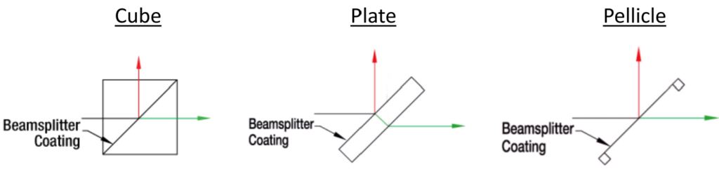
Beamsplitters find applications in laser systems, optical interferometry, fluorescence studies, and various biomedical instruments. They are available in three primary forms: plate, pellicle, and cube beamsplitters. Each type utilizes a partially reflecting coating, but they differ in construction, particularly regarding their power-handling capabilities.
Do You Know? Beamsplitter is also called Polarizing beamsplitter.

What is Beamsplitter?
Plate beamsplitters are manufactured using a coated substrate. Consequently, they exhibit beam offset and may produce ghost reflections from the second surface. Cube beamsplitters address the issue of beam displacement by operating at a 0° angle of incidence and positioning the coated surface between two right-angle prisms. However, power handling may be limited if epoxy is used to bond the prisms, and ghost reflections from the entry and exit faces can still occur.
Pellicle beamsplitters, on the other hand, appear to offer solutions by stretching an elastic membrane (sometimes coated) over a metal frame until it becomes very thin. Nonetheless, coating options are restricted, and they generally provide lower power handling compared to cube beamsplitters. When dealing with laser light, plate or cube beamsplitters typically offer the best balance between optical performance and power handling.
Once you’ve determined the required power-handling capacity and tolerance for ghost reflections, the next step in selecting a beamsplitter is choosing the appropriate coating. Consider whether it needs to operate exclusively at specific laser wavelengths (laser line), cover a wide range of wavelengths (broadband dielectric and hybrid coatings), separate s- and p-polarizations (polarizing coatings), or maintain the polarization ratio of the reflected and transmitted beams (non-polarizing and broadband hybrid coatings).
Regardless of your application, CVI Laser Optics provides both off-the-shelf and custom solutions to meet your specific needs. Continue reading to narrow down your search based on beamsplitter type: plate, cube, or integrated construction for variable attenuation.
Beamsplitter Background
Nonpolarizing beamsplitters are commonly employed to divide optical beams into two separate paths.
Different types of beamsplitters, such as cubes, plates, and pellicles, are available, but detailed information regarding the optical properties of their output light is often lacking.
In our study, we explore how the throughput, split ratio, and output polarization of 50:50 cube, 50:50 plate, and 50:50 pellicle beamsplitters are influenced by spatial variations and angles of incidence.
Basic Types of Beamsplitter
They are available in three primary types: plate, pellicle, and cube beamsplitters.
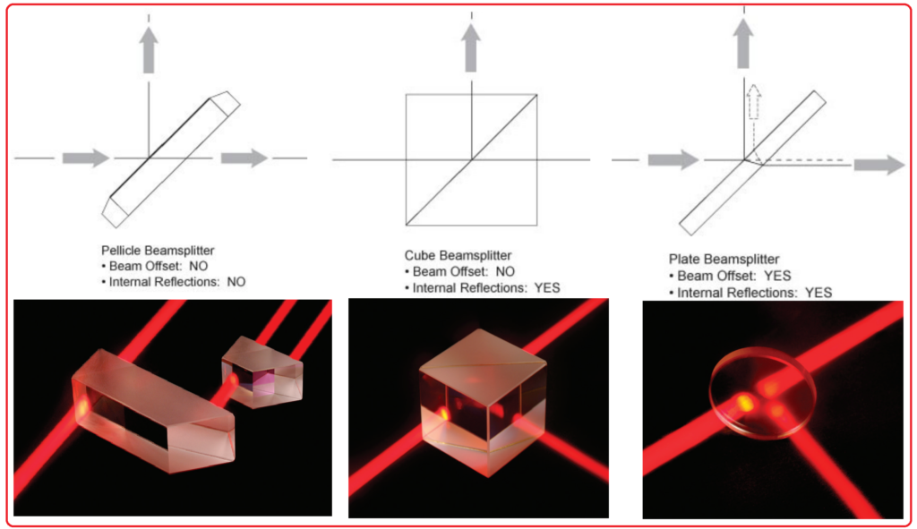
Plate Beamsplitters:
Plate beamsplitters are essentially flat substrates featuring a partially reflecting coating on a single surface, which serves to split an optical beam based on power or wavelength characteristics. The unique construction of plate beamsplitters, devoid of epoxy or optical contacting, inherently equips them for high-energy applications. The power-handling capabilities are contingent on the specific coating type employed, with options offering very high laser damage thresholds (up to 10 J/cm², 20 ns pulse, 20 Hz @ 1064 nm) being available.
Plate beamsplitters function at an angle of incidence set at 45°, with the incident beam initially encountering the primary coated surface and undergoing partial reflection. Subsequently, as the remaining portion of the beam traverses through the substrate, it experiences some degree of lateral displacement or offset.
Upon reaching the back surface of the substrate, a small fraction of the light is reflected back along the path of the incident beam, resulting in the creation of a ghost beam with a minimal displacement (approximately 0.3 times the thickness of the substrate). To mitigate this effect and optimize transmission of the beamsplitter, an anti-reflective (AR) coating is applied to the back surface of the substrate.
Cube Beamsplitters:
A cube beamsplitter is essentially constructed from two prisms, with one of them featuring a partially-reflecting coating, and it is primarily used to split an optical beam based on power or polarization characteristics. Cube beamsplitters incorporate antireflection coatings on both the entry and exit faces, which serve to minimize optical losses and reduce the occurrence of ghost reflections (although they may still be present to some extent).
The distinctive advantage of cube beamsplitters lies in their ability to eliminate beam displacement, all while maintaining robustness and durability, as they are not particularly fragile. They are straightforward to mount and exhibit mechanical resilience. However, it’s important to note that the presence of an interface can impose limitations on power handling, especially if epoxy is utilized for bonding.
At CVI Laser Optics, a range of high damage threshold products is available, which employ epoxy-free bonding techniques such as optical contacting and our innovative Chemically Active Direct Bonding® technology. These advancements enable cube beamsplitters to withstand high laser power levels, reaching up to 10 J/cm² at 1064 nm.
To ensure optimal spectral performance and a well-maintained transmitted wavefront, it is advisable to use cube beamsplitters with collimated or near-collimated light. The utilization of convergent or divergent beams may introduce unwanted spherical aberration into an optical system. Additionally, in cases where one of the prisms is marked with a dot, it signifies the coated prism. For optimal performance, the optical beam should initially pass through this prism.
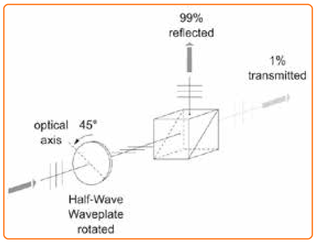
A helpful application tip: Polarizing cube beamsplitters can be effectively employed for optical isolation purposes or as a continuously variable beamsplitter when used in conjunction with a waveplate.
Power, wavelength, or polarization Separation:
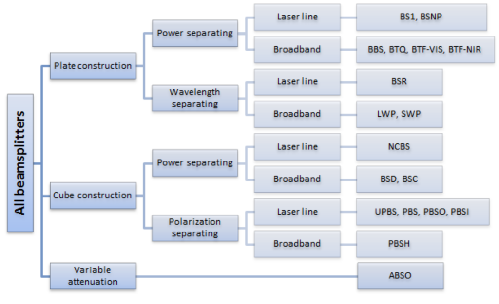
Once you have determined the construction type of beamsplitter that aligns with your requirements regarding power handling and tolerance to beam displacement, the next step is to further refine your choice based on how the beamsplitter should interact with light. Beamsplitters come in different categories based on their functionality:
- Power Separating Beamsplitters: These beamsplitters are designed to split an incoming beam into two orthogonal paths. Additionally, they can combine portions of two different beams into a single path, effectively creating a mixed beam. When equipped with a broadband coating, power separating beamsplitters allow for the convenient blending of beams with varying wavelengths into a single path. Some power separating beamsplitters are non-polarizing, meaning their performance does not significantly differ between s-polarized and p-polarized beams. Others may exhibit some degree of polarization sensitivity, but averaging the performance for both types of polarization yields consistent transmission or reflection values across the operating wavelength range.
- Wavelength Separating Beamsplitters: These beamsplitters incorporate dichroic coatings to reflect light at a specific wavelength or within a certain band while simultaneously transmitting light at another wavelength or band. Wavelength separating beamsplitters are particularly useful for applications where components of a laser beam need to be separated based on their wavelength. They are also employed to efficiently combine different wavelengths or bands with minimal loss, making them suitable for high-power applications.
- Polarization Separating Beamsplitters: These specialized beamsplitters are optimized to reflect s-polarized light while efficiently transmitting p-polarized light. They are typically designed for use at specific laser wavelengths or over a broad range of wavelengths. Polarization separating beamsplitters offer a method to both combine and divide laser beams of varying wavelengths, provided that the polarizations of the two beams are (or can be adjusted to be) orthogonal to one another.
Each type of beamsplitter serves specific optical needs, so selecting the most appropriate one depends on the desired application and performance criteria.
Beamsplitters Selection Guide:
Applications of Polarizing Beamsplitters:
- Offered with parallel or orthogonally propagating output beams
- Provide a high 1,000:1 contrast ratio in both output beams
- Maintain λ/8 Transmitted Wavefront Distortion (TWD) in both output beams
- Ensure arcsecond-level beam parallelism
Benefits of Polarizing Beamsplitters:
- Compact and space-efficient design
- Deliver nearly distortion-free output
- Accurately position output beams
- Provide symmetrical and consistent performance.
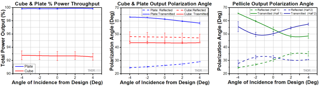
What are Output Optical Properties of Beamsplitters with Angle of Incidence?
Plate beamsplitters offer excellent throughput and split ratios while being less sensitive to changes in polarization angle.
Cube beamsplitters provide decent throughput and maintain polarization angles, but their split ratios depend significantly on the angle of incidence.
Pellicle beamsplitters provide high throughput but exhibit large variations in split ratio and polarization angle. There is spatial dependence within measurements when comparing one half of the pellicle to the other.
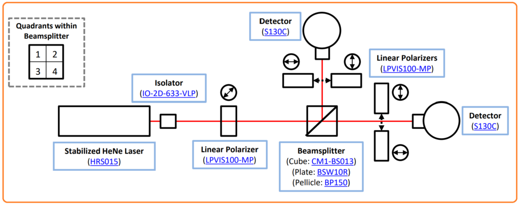
Experimental Setup
- We utilized a stabilized HeNe laser (633 nm) aligned with an isolator and linear polarizer set at a 45° angle to produce equal amounts of S- and P-polarized light.
- Each 1″ beamsplitter (cube, plate, and pellicle) was divided into four quadrants and affixed to a rotation stage.
- We employed two polarizers, one designed to block S-polarization and another optimized for blocking P-polarization, to measure the quantity of polarized light emitted from both arms of the beamsplitter.
- Power measurements were taken with and without polarizers at angles of -4°, 2°, 0°, 2°, and 4° relative to the optimal angle of incidence within each quadrant (as illustrated in the figure below).

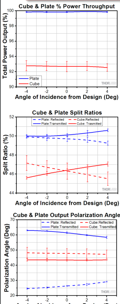
Cube and Plate Beamsplitters Comparison
In this analysis, we are examining the throughput, split ratio, and resulting polarization angle of a 50:50 cube beamsplitter and a 50:50 plate beamsplitter as a function of the angle of incidence.
The plate beamsplitter demonstrates optimal throughput and closely matches the anticipated split ratio, but it introduces alterations to the polarization state of the light.
On the other hand, the cube beamsplitter offers satisfactory throughput and preserves the polarization angle of the incident light. However, the split ratio is notably influenced by changes in the angle of incidence.
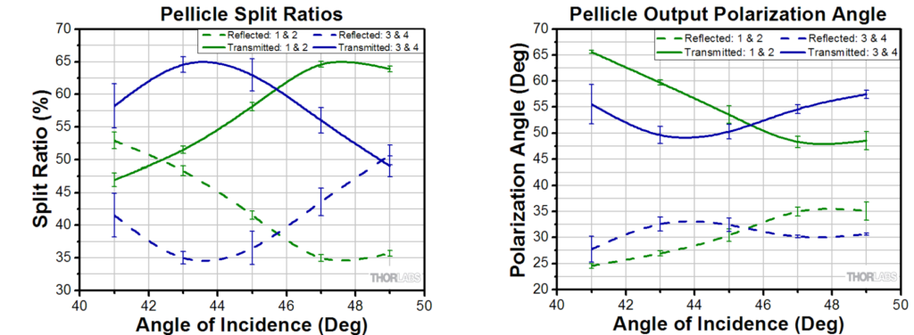
Pellicle Beamsplitters Results
In this section, we extend our analysis to the 50:50 (R:T) pellicle beamsplitter.
The pellicle beamsplitter exhibited excellent throughput; however, the split ratio was influenced by the angle of incidence, and the polarization angle was altered for both output beams. Additionally, there was a wide range of measurements observed across the four quadrants.
Furthermore, we noted a spatial dependence in the measurements, with one half of the pellicle consistently yielding results that differed from the other half.
Experimental Limitations
In this section, we address the limitations of our experimental setup:
- Limited Quadrant Measurements: We recorded only a single measurement in each quadrant, assuming minimal spatial dependence within individual quadrants.
- Single Wavelength Testing: Our analysis focused solely on light at a single wavelength (633 nm).
- Single Beamsplitter Assessment: We assessed only one cube, plate, and pellicle beamsplitter, assuming no significant variations between coating batches.
- Limited Polarization Evaluation: Our measurements focused on the rotation of the polarization ellipse and did not include an assessment of polarization linearity.