Weigh-in-Motion (WIM) systems employ various sensor technologies, with bending plates, piezoelectric sensors (quartz, polymer, and ceramic), and load cells being the most prevalent. The subsequent sections offer a concise exploration of each technology along with typical site configurations.
What is Weigh In Motion (WIM) System?
A Weigh-in-Motion (WIM) system is a technology used to measure the weight and other characteristics of vehicles as they travel on roads or highways without requiring them to stop. It is primarily used for traffic monitoring, weight enforcement, and collecting data related to vehicle size, weight distribution, and axle loadings. WIM systems typically consist of sensors embedded in the road surface, data collection equipment, and software for processing and analyzing the collected data.
Bending Plate System Sensor Technologies
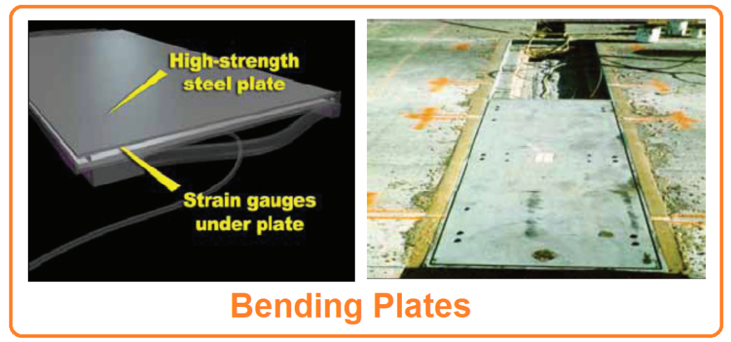
A bending plate system, which falls under the category of sensor technologies, utilizes steel plates equipped with strain gauges, as depicted in Figure IV-1. As vehicles pass over these plates, the strain generated by the vehicle’s weight is detected and transformed into a dynamic weight measurement. To estimate the static load, the measured load is multiplied by an associated calibration factor.
Layout of Bending Plate System
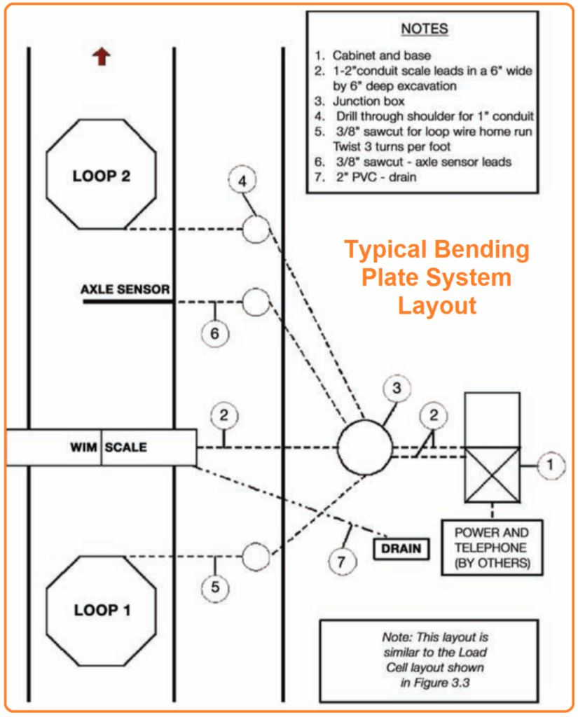
A standard site layout for a bending plate system comprises several key components, including WIM scales, inductive loops, and additional support equipment such as processors, communication devices, and operational software, as illustrated in Figure IV-2. Typically, one or two bending plates are positioned within the travel lanes, oriented perpendicular to the direction of travel. In the case of two scales, they can be positioned side by side or staggered by a distance of approximately 16 feet. Additionally, two inductive loops are strategically placed both upstream and downstream from the scales. These loops serve multiple purposes, including vehicle detection, speed measurement, and assessment of axle spacing.
Piezoelectric Sensor Systems
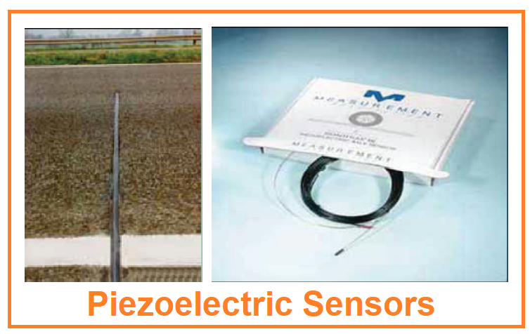
Piezoelectric sensors function by detecting changes in voltage induced as a vehicle traverses over the sensors, as depicted in Figure IV-3. Similar to other WIM sensor types, the static load is estimated by utilizing the measured load in conjunction with a calibration factor. Piezoelectric materials employed in these sensors can encompass polymer-based molecular chains (e.g., polyvinylidene fluoride), ceramics (e.g., lead zirconate titanate), or crystals (e.g., quartz).
Polymeric and ceramic piezoelectric sensors are the more cost-effective alternatives among WIM sensors. However, they exhibit sensitivity to temperature variations, rendering their performance less suitable for enforcement applications. For instance, the BL WIM sensor utilized by ConnDOT Planning demonstrates temperature sensitivity, with a reported sensitivity of approximately 0.2% per degree Fahrenheit, typically dependent on the type of grout used. This temperature dependence becomes particularly problematic on sunny days with cool nights when pavement temperatures undergo significant fluctuations.
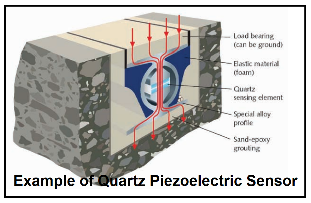
In contrast, quartz crystal piezoelectric sensors have exhibited superior linearity and stability even in the face of fluctuating temperatures. Figure IV-4 presents an example of a quartz-based sensor. In this configuration, the sensor housing plays a critical role in isolating vertical forces and minimizing the impact of horizontal forces.
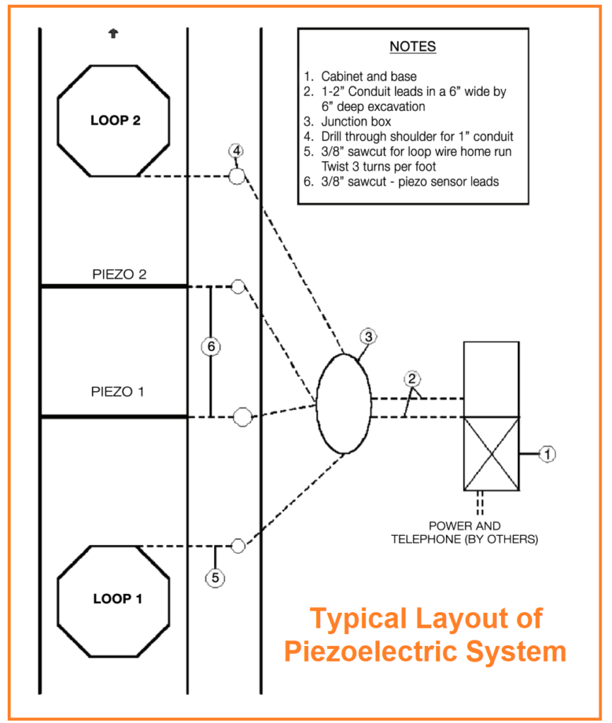
Typical Layout of Piezoelectric System
In a typical site layout for polymeric and ceramic piezoelectric sensors, these sensors are embedded in the pavement perpendicular to the direction of travel, as illustrated in Figure IV-5. After installation using grout, the sensors are smoothed flush with the pavement surface. They span the entire travel lane to ensure that both sets of tires of a vehicle pass over them. Inductive loops are also employed to detect vehicles, determine vehicle speeds, and assess axle spacing.
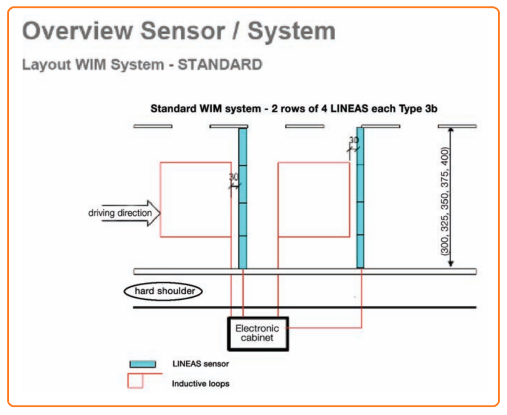
For a standard Kistler quartz piezoelectric WIM scale configuration, you can refer to Figure IV-6. This layout involves two rows, each equipped with four quartz piezoelectric sensors, all oriented perpendicular to the travel lane. In the United States, various staggered half-lane configurations have been implemented for diverse purposes. These configurations aim to reduce the influence of vehicle dynamics, enhance accuracy, and, in some instances, lower system costs by installing fewer sensors. However, fewer sensors may result in reduced accuracy.
As with other WIM systems, the estimation of static weight relies on the use of a calibration factor.
Load Cell-Based Weigh-in-Motion (WIM) Sensor System
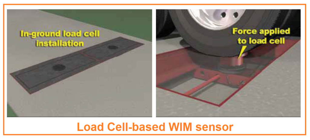
In a load cell-based Weigh-in-Motion (WIM) sensor system, each scale mechanism incorporates a centrally mounted load cell, as depicted in Figure IV-7. These load cells are positioned to cover the entire traffic lane’s width. Load transfer tubes transmit all loading experienced on the weighing surface sensor to the load cell. Typically, a configuration includes two six-foot long scales that collectively span one lane width. These scales effectively weigh the wheels on both sides of an axle simultaneously. They are mounted within a sturdy frame and installed in a vault that is level with the road surface.
Typical Load Cell System Layout
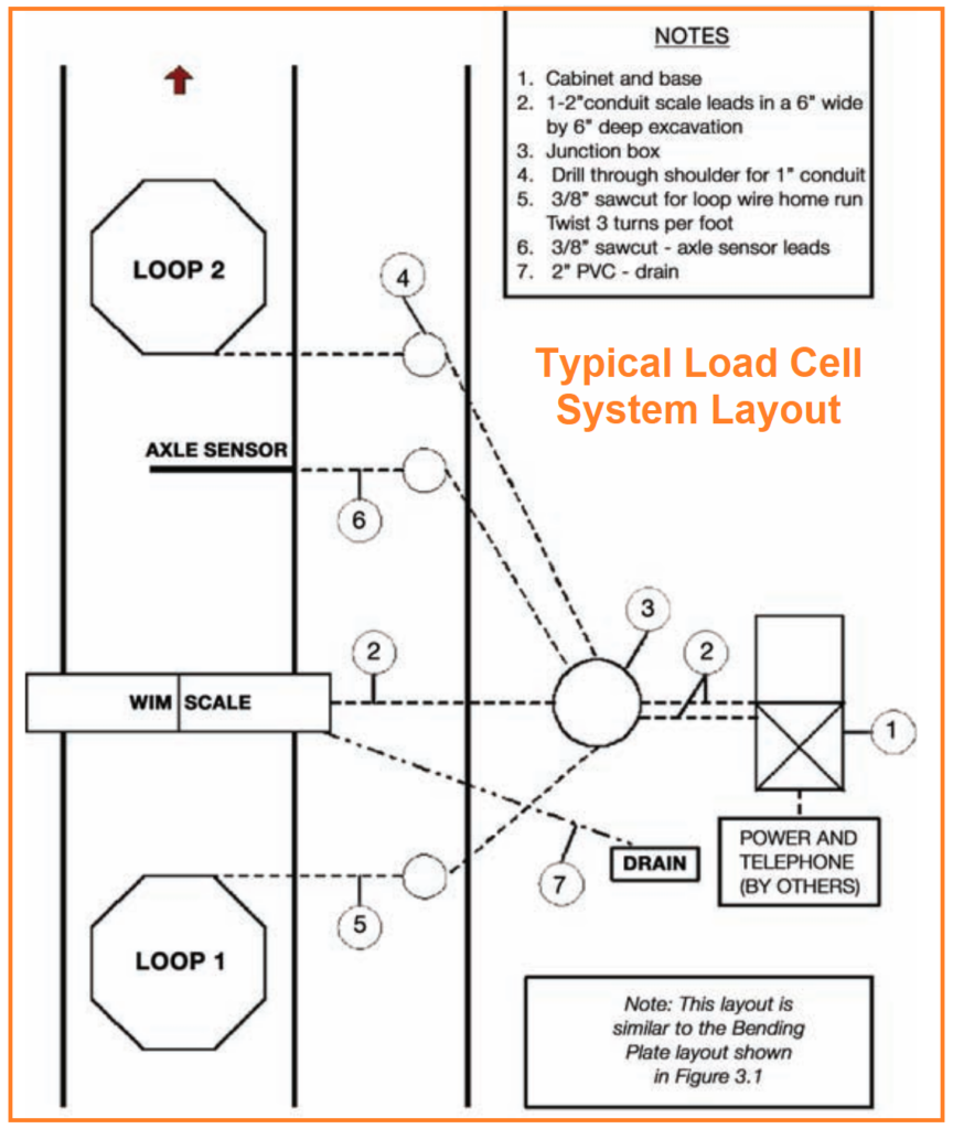
In a typical site layout for load cell-based Weigh-in-Motion (WIM) systems, each load cell is equipped with two scales that jointly detect an axle’s presence and simultaneously measure both the right and left sides of the axle.
These measurements are then summed to determine the axle weight accurately. An inductive loop, in combination with an axle sensor, is typically installed, with the inductive loop positioned upstream to identify approaching vehicles. If a second loop is employed, the spacing between axles is used to calculate vehicle speed. Similar to the configuration shown in Figure IV-2, the load cell site layout closely resembles the bending plate setup.
Comparing Current Weigh-in-Motion (WIM) Technologies
When comparing current Weigh-in-Motion (WIM) technologies, it’s essential to recognize that the accuracy of a WIM scale is influenced by various factors, including sensor technology, site conditions, truck characteristics, and driver behavior. Therefore, quantifying the accuracy of each sensor technology becomes challenging. Instead, a qualitative comparison was conducted, focusing on factors such as ease of installation, maintenance, safety, and cost, to determine the most suitable technology or technologies for Connecticut.
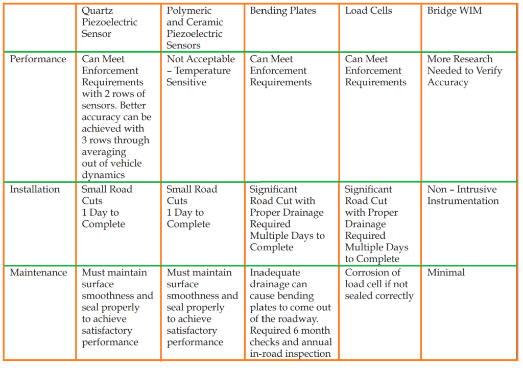
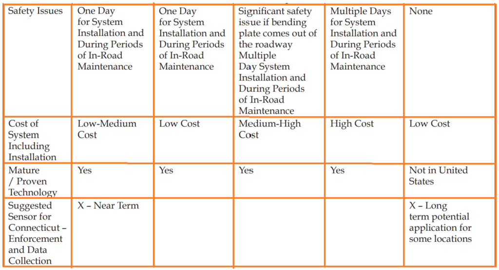
Polymeric and ceramic piezoelectric sensors, given their temperature sensitivity, were deemed unsuitable as they couldn’t consistently meet enforcement requirements. Load cells and bending plates, while capable of providing accuracy comparable to quartz piezoelectric sensors, were not recommended due to their extended installation time, posing safety concerns. Additionally, bending plate sensors could become safety hazards over time if not properly secured, and load cell installations were found to be notably costlier than alternative technologies.
Developing WIM Sensor Technologies Through Bridge WIM
One of the primary areas of development in Weigh-in-Motion (WIM) sensor technology is focused on bridge WIM systems. These systems offer a significant advantage over traditional technologies like piezoelectric sensors, bending plates, and load cells due to their non-intrusive nature. This non-intrusiveness is especially advantageous as it eliminates the need to install and maintain WIM scales within the pavement, addressing safety concerns and reducing costs.
Although various alternative technologies, such as capacitance mats, vertical strain reducers, fiber optical sensors, and microwave sensors, have been explored, their performance in real-world applications has been limited in terms of accuracy and reliability. Consequently, these alternative technologies are currently not considered viable options for WIM sensors in enforcement and data collection applications in Connecticut.
Bridge WIM (BWIM) is a specific approach within this technology. It involves determining a truck’s weight as it crosses a highway bridge by measuring the strain or deflection of the bridge’s structural components. Preliminary research conducted in Connecticut has shown the feasibility of employing long-term bridge monitoring systems for BWIM purposes.