This article is about Radio Protocol Architecture of E-UTRAN where we explained about Control Plane and User Plane in LTE.
What is User Plane?
In the Evolved Universal Terrestrial Radio Access Network (E-UTRAN), the user plane handles the transmission of user data between the user equipment (UE) and the core network. An IP packet destined for a UE is encapsulated in a protocol specific to the Evolved Packet Core (EPC) and tunneled between the Packet Data Network Gateway (PDN-GW) and the eNodeB before being transmitted to the UE. The tunneling protocols vary across different interfaces, with the 3GPP-specific GPRS Tunneling Protocol (GTP) being utilized over core network interfaces such as S1 interface and S5/S8 interfaces.
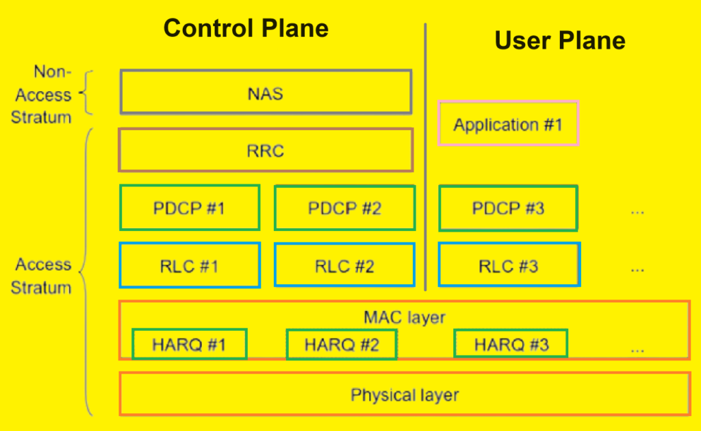
The user plane protocol stack in E-UTRAN, as illustrated in Figure below, comprises the Packet Data Convergence Protocol (PDCP), Radio Link Control (RLC), and Medium Access Control (MAC) sublayers. These sublayers terminate at the eNodeB on the network side.

Data Handling During Handover.
Due to the lack of a centralized controller node in E-UTRAN, the responsibility for data buffering during handover, necessitated by user mobility, falls to the eNodeB. The PDCP layer is specifically tasked with data protection during handover. Meanwhile, both the RLC and MAC layers are reset and start afresh in the new cell post-handover.
User Plane Architecture.
In LTE’s user-plane architecture, data transmission and reception are structured through a layered protocol stack. Each layer in the stack provides services to the layer above it and utilizes services from the layer below. This interaction involves the exchange of Service Data Units (SDUs) and Protocol Data Units (PDUs).
Data Flow in the User-Plane.
- Transmitting Side:
- At the transmitting side, each layer receives an SDU from the higher layer. For example, the RLC (Radio Link Control) layer receives PDUs from the PDCP (Packet Data Convergence Protocol) layer. From the PDCP’s perspective, these packets are PDCP PDUs, while from the RLC’s perspective, they are RLC SDUs.
- The RLC layer processes these SDUs and creates RLC PDUs, which are then sent to the MAC (Medium Access Control) layer. From the MAC’s perspective, these packets are MAC SDUs.
- This process continues down the stack until the data reaches the physical layer for transmission.
- Receiving Side:
- On the receiving side, the process is reversed. Each layer receives PDUs from the layer below, processes them, and passes them up as SDUs to the layer above.
Byte Alignment in Protocol Stack.
An essential design feature of the LTE protocol stack is the byte alignment of all PDUs and SDUs. This byte alignment facilitates efficient handling by microprocessors, which typically process data in byte units. To reduce processing requirements further, the headers created by the PDCP, RLC, and MAC layers are also byte-aligned. This approach ensures that microprocessors can efficiently manage the data packets.
However, byte alignment sometimes necessitates the use of unused padding bits in the headers. While this design choice optimizes processing efficiency, it results in a slight waste of potential data capacity due to these padding bits.
What is Control Plane?
The control plane manages signaling between the UE and the core network, primarily focusing on establishing and maintaining the connection. The control plane protocol stack between the UE and the MME is depicted in Figure below, where the greyed region represents the access stratum protocols. These lower layers perform similar functions to those in the user plane, with the exception that header compression is not used in the control plane.

The Radio Resource Control (RRC) protocol, identified as ‘Layer 3’ in the access stratum protocol stack, serves as the primary controlling function within the access stratum. The RRC is responsible for establishing radio bearers and configuring all the lower layers through RRC signaling between the eNodeB and the UE.
Final Thoughts.
The radio protocol architecture of E-UTRAN delineates the distinct functions and protocols involved in managing both the user and control planes. The user plane focuses on the efficient transmission and protection of user data, particularly during handovers, while the control plane emphasizes the setup, maintenance, and configuration of radio connections and bearers. The integration of these protocols ensures the seamless operation of LTE networks, catering to the high mobility and data demands of modern users.