An Inertial Navigation System (INS) is a navigation aid that utilizes a combination of accelerometers, gyroscopes, and sometimes magnetometers to determine the position, orientation, and velocity of a moving object without the need for external references. INS operates based on the principles of Newtonian physics and the laws of motion.
Here’s how an INS typically works:
- Accelerometers: These sensors measure the linear acceleration experienced by the object along each axis. By integrating these acceleration measurements over time, the system can determine the velocity of the object.
- Gyroscopes: Gyroscopes measure the rate of rotation or angular velocity of the object around each axis. Integration of these measurements over time provides the orientation or attitude of the object.
- Magnetometers (optional): Magnetometers detect the Earth’s magnetic field and are sometimes used to provide additional information about the object’s orientation, particularly in applications where gyroscopes alone may not be sufficient (e.g., in environments with magnetic interference).
Inertial Navigation System Components
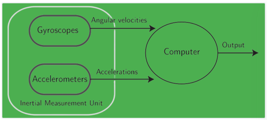
An Inertial Navigation System (INS) typically consists of two main components:
- Inertial Measurement Unit (IMU): This module contains sensors such as accelerometers, gyroscopes, and sometimes magnetometers. These sensors measure the accelerations and rotations experienced by the system along various axes. The IMU provides raw data about the system’s motion, which is then processed by the system’s computer.
- Computer: The computer within the INS performs navigation calculations using the data provided by the IMU. It integrates the sensor data over time to determine the system’s position, orientation, and velocity relative to its starting point.
How Inertial Navigation System Works?
The operation of an INS can be summarized as follows:
- Initially, the system is provided with its position and velocity from an external reference source, such as a GPS receiver or human input.
- Once initialized, the INS continuously measures accelerations and rotations using the IMU.
- The computer integrates these measurements over time to calculate the system’s updated position, orientation, and velocity.
- Unlike systems that rely on external references for navigation, an INS does not require continuous input from external sources once it has been initialized. This independence from external references is a significant advantage, especially in environments where such references may be unavailable or unreliable.
Inertial Navigation System Explanation
Gyroscopes and accelerometers play important roles in an Inertial Measurement Unit (IMU) within an Inertial Navigation System (INS) for determining the orientation and motion of an aircraft. Here’s a breakdown of their functions and how they contribute to navigation:
Gyroscopes:
- Gyroscopes measure the angular velocity of the aircraft relative to an inertial reference frame, such as the Earth’s surface.
- By integrating the angular velocity measurements over time and using the initial orientation of the aircraft as a reference, the INS can continuously determine the aircraft’s orientation (attitude) in the inertial reference frame.
- Gyroscopes provide essential information about the aircraft’s rotational motion, allowing the INS to maintain accurate knowledge of its orientation throughout flight.
Accelerometers:
- Accelerometers measure the linear acceleration experienced by the aircraft along each of its axes.
- However, accelerometers measure acceleration relative to the moving system itself, as they are fixed to the aircraft and rotate with it. Therefore, they cannot directly determine the aircraft’s orientation relative to the Earth.
- Accelerometers provide information about how the aircraft is accelerating relative to itself, indicating whether it is moving forward, backward, left, right, upward, or downward in the aircraft’s reference frame.
- By combining accelerometer measurements with gyroscopic data (which provides orientation information), the INS can determine the linear acceleration of the aircraft in the inertial reference frame.
- Integration of these inertial accelerations over time, using initial velocity as the starting condition, allows the INS to calculate the inertial velocities of the aircraft. Further integration, using initial position as the starting condition, yields the inertial position of the aircraft.
- These integration processes involve complex kinematic equations and considerations of relative movement, which are typically studied in advanced courses of mechanics.
Overall, gyroscopes and accelerometers work together within an INS to provide continuous and accurate information about the aircraft’s orientation, velocity, and position in an inertial reference frame, allowing for autonomous navigation without the need for external references.
Errors in the Inertial Navigation System:
Errors in inertial navigation systems (INS) primarily arise from integration drift, where small errors in the measurements of acceleration and angular velocity accumulate over time, leading to progressively larger errors in velocity and position. This integration drift is a fundamental limitation of Inertial Navigation System and can result in significant inaccuracies in position estimation if not periodically corrected.
Here are some key points regarding errors in Inertial Navigation System:
- Integration Drift: Integration of acceleration and angular velocity measurements leads to errors in velocity and position. These errors accumulate over time and increase at a rate roughly proportional to the duration since the initial position was input.
- Cumulative Nature: Since the new position is calculated based on the previous position and the measured acceleration and angular velocity, errors in position are cumulative and grow over time.
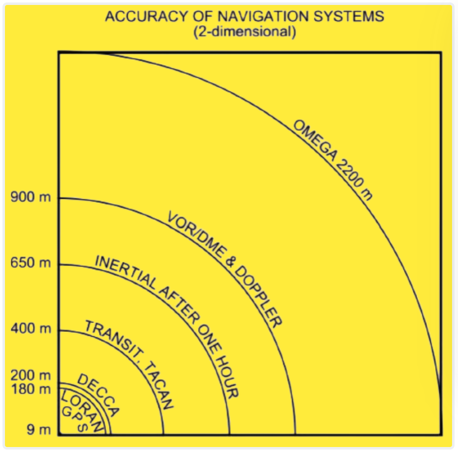
- Accuracy: Despite integration drift, a good-quality Inertial Navigation System typically maintains accuracy within certain limits. For example, the inaccuracy may be less than 0.6 nautical miles per hour in position and on the order of tenths of a degree per hour in orientation.
To mitigate the effects of integration drift and improve overall navigation accuracy, Inertial Navigation System is often supplemented with other navigation systems, typically non-autonomous systems like GPS. This hybrid approach combines the strengths of both systems while compensating for their respective weaknesses.
One common method for combining Inertial Navigation System with other navigation systems is through filtering techniques such as Kalman filtering. Kalman filtering allows for the estimation of the true position by weighting the measured position from external sensors (e.g., GPS) and the predicted position from INS based on the magnitude of their respective errors.
By properly combining both sources of information and adjusting the weighting factors, the errors in position and velocity can be stabilized over time, resulting in improved overall navigation accuracy.
While the equations and intricacies of Kalman filtering are beyond the scope of introductory courses, they are essential tools in the design and implementation of integrated navigation systems for various applications, including aerospace and maritime navigation.