The Instrument Landing System (ILS) is a ground based radio navigation system that provides precision guidance to aircraft during the approach and landing phase, especially in low visibility conditions. It consists of a series of radio signals transmitted by ground-based equipment located at the runway’s end, which are received by onboard instruments in the aircraft cockpit.
What is Instrument Landing System?
The Instrument Landing System (ILS) stands as a cornerstone of aviation safety, particularly in adverse weather conditions or low visibility scenarios. Comprising a localizer and a glideslope, the ILS offers precise lateral and vertical guidance to aircraft during their final approach to the runway. Pilots rely on the signals transmitted by the localizer and glideslope to align their aircraft with the correct path and maintain the appropriate descent profile. These critical components work in tandem, enabling aircraft to approach the runway with remarkable accuracy, ultimately enhancing the safety and efficiency of landings.
Originating from early 20th-century developments in precision landing systems, the ILS emerged as a global standard following World War II. While alternative systems like ground-controlled approach (GCA) and microwave landing system (MLS) were introduced, the ILS’s reliability and effectiveness solidified its position as the preferred choice for precision approaches. Despite its long-standing dominance, the evolution of technology, particularly with the rise of global navigation satellite systems (GNSS), is gradually reshaping the landscape of aviation navigation.
With the increasing availability and accuracy of GNSS-based approaches, there is a growing trend towards transitioning away from traditional ILS installations. GNSS systems offer comparable precision at a fraction of the cost, making them an attractive option for airports seeking to modernize their infrastructure. As more airports adopt GNSS-based approaches, the eventual replacement of ILS at many locations seems likely, signaling a significant shift in the way aircraft navigate and land in the future.
How ILS System Works?
The Instrument Landing System (ILS) works through a combination of ground-based radio signals and onboard aircraft equipment to provide precise guidance to pilots during approach and landing, particularly in low visibility conditions.
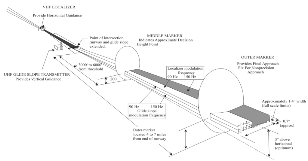
The ILS system consists of two main components: the localiser for horizontal guidance and the glideslope for vertical guidance. The localiser aerial emits signals between 108.1 MHz and 111.975 MHz, which are modulated to provide lateral guidance to the aircraft. If an aircraft receives a tone of 90 MHz, it indicates that the aircraft is left of the localiser, while a tone of 150 MHz signifies being on the right. This helps pilots adjust their course to align with the runway centerline.
On the other hand, the glideslope aerial emits signals between 328.6 MHz and 335.4 MHz to provide vertical guidance. This component assists pilots in maintaining the correct rate of descent to ensure a smooth approach and landing. By integrating both horizontal and vertical guidance signals, the ILS system enhances precision and reliability, enabling pilots to navigate safely even in adverse weather conditions or low visibility situations.
In essence, the ILS system works by utilizing ground-based radio signals emitted from localiser and glideslope aerials to guide aircraft along the correct approach path. Pilots rely on these signals, along with onboard equipment, to maintain alignment with the runway and execute a safe landing, ultimately enhancing operational efficiency and safety in aviation.
ILS Components
Key components of the ILS system include:
- Localizer (LLZ): The localizer provides lateral guidance, guiding the aircraft along the centerline of the runway. It emits radio signals in the horizontal plane, allowing pilots to align the aircraft with the runway’s extended centerline.
- Glide Slope (GS): The glide slope provides vertical guidance, helping the aircraft maintain a predetermined descent path toward the runway. It emits radio signals at a specific angle above the horizontal plane, allowing pilots to control the aircraft’s descent rate.
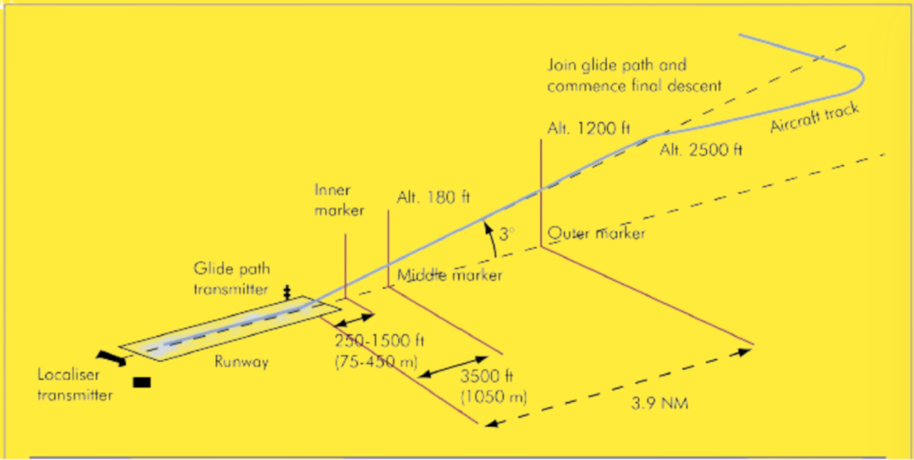
- Marker Beacons: Marker beacons are additional ground-based transmitters that provide distance and altitude information to the aircraft. They indicate specific points along the approach path, such as the outer marker (OM), middle marker (MM), and inner marker (IM), helping pilots gauge their position and altitude during the approach.
- Course Deviation Indicator (CDI): The CDI is a cockpit instrument that visually displays the aircraft’s deviation from the localizer and glide slope signals. Pilots use the CDI to make course corrections and maintain alignment with the runway.
The Instrument Landing System (ILS) is a important system for precision approach in civil aviation, offering both glideslope and track guidance. Pilots rely on the continuous transmission of ILS signals to interpret approach guidance during their descent. As they navigate the ILS approach, pilots descend with guidance until they reach the decision height (DH), where they must decide whether to proceed with landing or initiate a go-around. All ILS installations must adhere to standards outlined in ICAO Annex 10, with performance categories assigned accordingly. Any deviations from these standards are communicated via NOTAMs (Notice to Airmen).

A typical Instrument Landing System consists of several components. The localizer transmitter provides azimuth guidance along the extended runway centerline, ensuring the aircraft stays on track horizontally. The glide path transmitter offers vertical guidance, helping maintain the correct descent angle toward the runway.
Marker beacons are utilized to establish precise range fixes along the horizontal plane, aiding pilots in determining their position during the approach. Additionally, some ILS installations incorporate Distance Measuring Equipment (DME) to provide continuous ranging capabilities beyond what marker beacons offer. Moreover, a low-power Non-Directional Beacon (NDB), referred to as a locator beacon, may be used to assist with intermediate approach guidance, guiding aircraft toward the final approach path marked by the ILS.
The ideal flight path during an instrument landing system approach occurs when the localizer and glide slope planes intersect. Pilots follow cockpit indications provided by the instrument landing system to navigate along this optimal flight path, ensuring alignment with the runway centerline and correct descent angle for a safe and precise landing.
Instrument Landing System Localizer.
The localizer is a vital component of the Instrument Landing System (ILS) that provides directional guidance along the extended centerline of the landing runway. Operating within the VHF band, it transmits signals on frequencies ranging from 108.10 to 111.95 MHz, with odd first decimals only (e.g., 108.30 MHz). The localizer transmitter antenna is positioned approximately 300 meters from the upwind end of the runway, aligned with the runway centerline.

Typically, the localizer antenna is constructed in a frangible manner, measuring about 20 meters wide and 3 meters high. It consists of dipole and reflector elements arranged to produce a composite field pattern with two overlapping lobes, as illustrated in below Figure. These lobes are transmitted on a single instrument landing system frequency and are modulated differently to aid receiver distinction.
During approach, the left lobe is modulated with a 90 Hz tone, forming the YELLOW sector, while the right lobe is modulated with a 150 Hz tone, creating the BLUE sector. A receiver positioned left of the centerline detects more of the 90 Hz modulation, resulting in a Difference in Depth of Modulation (DDM). Conversely, a receiver to the right of the centerline receives more 150 Hz modulation. The DDM causes the vertical indicator needle to deflect, indicating the need for course corrections.
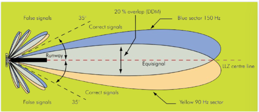
The localizer centerline is defined by the line along which the DDM is zero. When an aircraft is precisely aligned with this line, there is no deflection of the needle, signaling that the aircraft is on the centerline of the runway. Pilots use this guidance to ensure accurate alignment with the runway centerline during approach and landing.
Localizer Range.
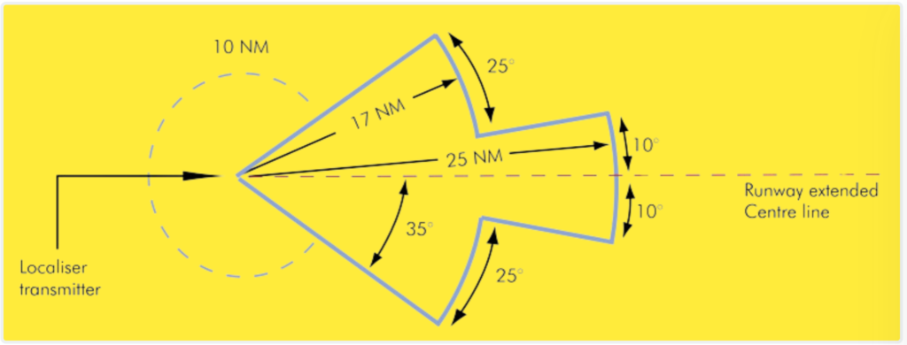
The range of the localizer signal extends linearly from the localizer centerline, with the Difference in Depth of Modulation (DDM) increasing in a linear fashion on each side of the centerline up to at least 3 degrees. Adequate localizer coverage is expected up to distances of 25 nautical miles (NM) within 10 degrees on either side of the centerline.
Furthermore, coverage must extend to distances of 17 NM between 10 and 35 degrees on either side of the centerline. Beyond this range, coverage should still be provided up to distances of 10 NM at angles greater than 35 degrees from the centerline for installations offering full coverage around the airport.
However, in cases where topographical features or operational requirements dictate, the coverage limit may be reduced. For example, it may be reduced to 18 NM within the ±10-degree sector and to 10 NM within the remaining coverage area. These specifications ensure that aircraft receive adequate localizer signals for precision approach and landing guidance across a wide range of approach angles and distances from the runway. Figure 5 illustrates the required horizontal coverage of the localizer signal.
Glide Path of Instrument Landing System
The glide path transmitting aerial is strategically positioned approximately 300 meters upwind from the threshold and about 120 meters from the centerline of the runway. This placement ensures that the glide path’s extension intersects the runway at the optimal touchdown point, allowing for adequate clearance over the threshold and any other objects or terrain during the landing approach.
Glide path transmission occurs in the UHF band across 40 spot frequencies ranging from 329.15 to 335 MHz. Utilizing the UHF band allows for the production of more accurate and narrow beams. Similar to the localizer transmission, the glide path signal is beamed in the vertical plane, consisting of two lobes with different modulations: a 90 Hz modulation for the upper lobe and a 150 Hz modulation for the lower lobe.
The Difference in Depth of Modulation (DDM) between these two lobes energizes the horizontal needle of the instrument, indicating whether the aircraft is in the 90 Hz lobe or the 150 Hz lobe. The intersection of these modulations defines the centerline of the glide path, typically set at a 3-degree angle from the horizontal but adjustable to accommodate specific local conditions, ranging from 2 to 4 degrees.
In some cases, such as London City Airport, the glide slope angle may exceed 4 degrees, reaching up to 5.5 degrees. A steep glide slope angle requires a higher rate of descent for normal turbojet aircraft. Additionally, it’s important to note that the glide path becomes curved and gradually flattens near the landing threshold, particularly relevant for fully automatic landing operations, which necessitate the use of a radio altimeter.
The positioning of the glide path aerial and the selection of the glide path angle depend on various factors, including acceptable rates of descent and approach speeds for aircraft, obstacle clearance requirements, horizontal coverage considerations, technical site constraints, the desire to reach the instrument landing system reference datum 50 feet above the threshold on the centerline, and the length of the runway. These interrelated factors inform the optimal placement and angle of the glide path to ensure safe and efficient approach and landing procedures.
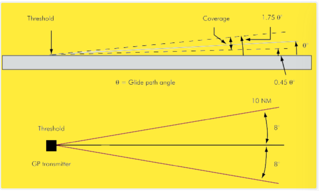
Glide Path Coverage
The coverage of the glide path extends 8 degrees on each side of the localizer centerline, spanning a distance of 10 nautical miles. In the vertical plane, the coverage ranges from 0.45 times the nominal glide path angle (θ) to 1.75 times the nominal glide path angle above the surface. It’s crucial to remember that reliable signals are only assured within the approved coverage zones. Signals received outside of these zones cannot be trusted for precision guidance during the approach. This coverage ensures that pilots receive accurate and reliable guidance along the glide path as they descend towards the runway threshold, optimizing safety and precision during the landing phase.
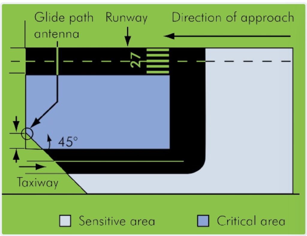
Critical and Sensitive Areas
The instrument landing system critical area is a designated space surrounding the localizer and glide path antennae, where all vehicles, including aircraft, are prohibited from entering during ILS operations. This exclusion zone is established to prevent any potential disturbances to the signal-in-space, ensuring the integrity of the ILS guidance system during critical landing phases.
Beyond the critical area lies the ILS sensitive area, which extends further and imposes controlled restrictions on the parking and movement of vehicles, including aircraft. The dimensions of the sensitive area vary depending on the size and type of aircraft present on the ground. For example, the sensitive area for a larger aircraft like a Boeing 747 is larger compared to a smaller aircraft like a Boeing 737. These measures are implemented to minimize the risk of interference with the instrument landing system signal, thereby maintaining the safety and reliability of the landing guidance system for all aircraft operating within the vicinity.
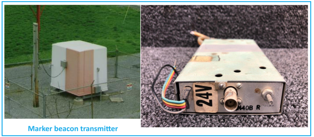
Marker Beacons of ILS System
Marker beacons are integral components of instrument landing systems (ILS) used in aviation, operating on the VHF frequency of 75 MHz (emission code N0NA2A). These beacons play a crucial role in providing pilots with range information during the approach phase of landing procedures. Typically, marker beacons are equipped with almost vertical beams, ensuring accurate transmission of signals to aircraft in their vicinity. The primary function of marker beacons is to indicate the aircraft’s distance from the runway threshold during the approach.
In most instrument landing system installations, two types of marker beacons are commonly utilized: the outer marker and the middle marker. Additionally, Category 2 or 3 ILS systems may incorporate an inner marker for enhanced precision during advanced landing operations. These marker beacons emit both audio and visual signals in the cockpit, alerting the pilot when the aircraft passes directly overhead.
Marker beacons operate on a standardized frequency of 75 MHz, eliminating the need for pilots to make frequency selections manually. However, advancements in navigation technology have led to the gradual replacement or supplementation of marker beacons with distance measuring equipment (DME) associated with the instrument landing system. This transition reflects the aviation industry’s continual efforts to improve navigation accuracy and efficiency while ensuring the safety of flight operations.
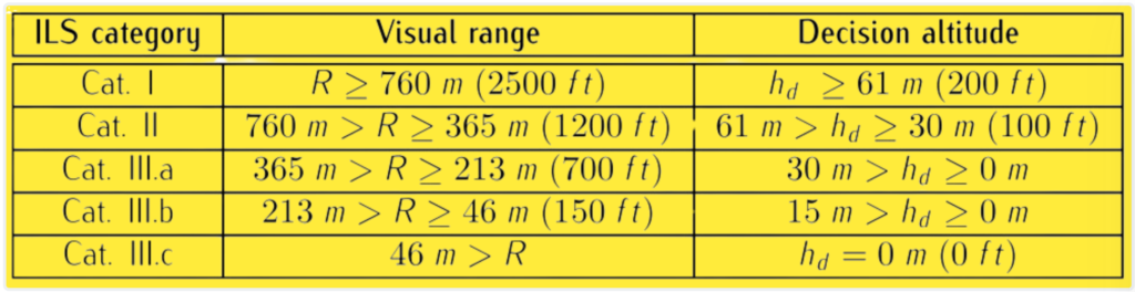
ILS Categories
The International Civil Aviation Organization (ICAO) categorizes Instrument Landing Systems (ILS) into different categories based on the visual range and decision altitude. The visual range refers to the longitudinal distance at which a pilot can clearly distinguish runway markings or lights, especially crucial during nighttime or adverse weather conditions. On the other hand, the decision altitude is the minimum altitude at which the pilot must decide whether to continue the approach or initiate a go-around if visual references are not established. These categories help pilots and air traffic controllers ensure safe and efficient landings, especially in low-visibility conditions.
Z-markers and Fan Markers
Z-markers and fan markers are two types of marker beacons utilized in aviation for providing range information during instrument landing system (ILS) approaches.
- Fan Markers: Fan markers emit a fan-shaped beam, which is rectangular and radiates vertically. This beam pattern ensures that signals are received by the aircraft only during the brief period when it passes through the beam. Fan markers are commonly used in standard instrument landing system installations and are effective in guiding aircraft during approach procedures.
- Z-Markers: Z-markers, on the other hand, have a dumbbell or bone-shaped pattern, with signals being received from the narrow portion of the pattern. This type of marker beacon is typically employed in situations where “timed” approaches are utilized. Z-markers are designed to provide range information to aircraft during specific phases of the approach, ensuring precise navigation guidance.
The polar diagram of the transmitted signal from both types of marker beacons resembles a vertical fan or funnel-shaped lobe. Unlike non-directional beacons (NDBs), which emit signals in all directions, marker beacons can only be received when an aircraft is directly overhead. This directional transmission characteristic enhances the accuracy of range information provided to pilots during instrument approaches, contributing to safer and more efficient landing operations.
History:
The development and testing of the Instrument Landing System (ILS) trace back to 1929 when trials began in the United States. Notably, pilot Jimmy Doolittle achieved a significant milestone by successfully taking off, flying, and landing an aircraft using instruments alone, marking a pivotal moment in aviation history. Subsequently, in 1932, a basic operational system was introduced at Berlin-Tempelhof Central Airport in Germany, known as the Lorenz beam or LFF after its inventor, C. Lorenz AG.
In 1941, the Civil Aeronautics Board (CAB) of the United States authorized the installation of the ILS at six locations, marking a significant step towards its widespread adoption. A milestone in ILS history occurred on January 26, 1938, when a Pennsylvania Central Airlines Boeing 247D conducted the first landing of a scheduled U.S. passenger airliner using the ILS. Despite adverse weather conditions, the aircraft successfully landed in a snowstorm solely relying on the Instrument Landing System.
Alternatives and Future of ILS.
Alternative systems to the Instrument Landing System (ILS) have been developed to address various limitations and to offer enhanced capabilities in different scenarios. Some of the notable alternatives to ILS include:
1. Microwave Landing System (MLS).
MLS was developed as a modern replacement for ILS and offers improved accuracy and flexibility. Unlike ILS, which uses VHF frequencies, MLS operates in the microwave frequency range, providing more precise guidance for aircraft during approach and landing. MLS also supports curved approaches and can accommodate multiple approach paths to a single runway, making it suitable for airports with complex layouts.
2. Global Navigation Satellite System (GNSS).
GNSS, including systems like GPS (Global Positioning System) and Galileo, offers a satellite-based alternative to traditional ground-based navigation aids like ILS. GNSS provides accurate position information to aircraft using signals from a constellation of satellites, enabling precise navigation and approach guidance. GNSS-based approaches, such as RNAV (Area Navigation) and RNP (Required Navigation Performance), offer flexibility and coverage in areas where ground-based navigation aids are limited or unavailable.
3. Visual Approach Slope Indicator (VASI) and Precision Approach Path Indicator (PAPI).
VASI and PAPI are visual aids installed alongside runways to provide vertical guidance to pilots during approach and landing. These systems use a combination of red and white lights to indicate whether the aircraft is above, below, or on the desired glide path. While not as precise as ILS, VASI and PAPI offer a simple and cost-effective means of guiding aircraft to the runway threshold, particularly in visual meteorological conditions.
4. Ground-Based Augmentation System (GBAS):
GBAS is a ground-based navigation system designed to enhance the accuracy and integrity of GPS signals for aircraft approaching and landing at airports. GBAS provides differential corrections to GPS signals, allowing for precision approach and landing guidance similar to ILS. GBAS offers improved accuracy and availability compared to traditional ILS and can support curved approaches and tailored approach paths for specific runway ends.
How does instrument landing system work?
On the other hand, the glide slope (GS) provides vertical guidance, assisting pilots in maintaining the correct descent profile as they approach the runway for landing. Together, these components help pilots navigate accurately and safely during the final stages of landing, especially in low visibility or adverse weather conditions.