A Neutral Earthing Resistor (NER), also known as a Neutral Grounding Resistor, is an electrical component used in power systems to limit the fault current that can flow through the neutral conductor of a transformer or generator. The primary purpose of a NER is to improve the safety and reliability of the power system by preventing excessive fault currents from damaging equipment and causing electrical fires.
![What is Neutral Earthing Resistor? Technical Guide [PDF]](https://paktechpoint.com/wp-content/uploads/2023/09/image-284-1024x777.png)
Here are the main functions and characteristics of a Neutral Earthing Resistor:
- Fault Current Limitation: In the event of a phase-to-ground fault in a power system, fault currents can flow through the neutral conductor. Without proper control, these fault currents can reach dangerously high levels. A NER is connected to the neutral point of the transformer or generator and limits the fault current to a safe level.
- Safety: By limiting fault currents, NERs help protect electrical equipment, such as transformers, generators, and cables, from damage due to short circuits. This enhances the overall safety of the power system.
- Arc Suppression: NERs can help suppress the formation of electrical arcs during faults, reducing the risk of explosions or fires in electrical enclosures.
- Voltage Stability: NERs can help stabilize the voltage levels in a power system during fault conditions, preventing overvoltages that could damage equipment.
- Adjustability: The resistance of a NER can be adjusted to control the fault current level as needed for specific applications. This allows for customization based on the characteristics of the power system.
- Monitoring: Many NER installations include monitoring systems that provide real-time information about fault currents and the status of the neutral grounding. This information helps operators and maintenance personnel make informed decisions.
- Compliance: NERs are often required to meet safety and regulatory standards, depending on the type of power system and its location. Compliance ensures that the power system operates safely and reliably.
Neutral Earthing Resistors are commonly used in medium and high-voltage power distribution systems, including industrial plants, utilities, and substations. Their proper selection, installation, and maintenance are essential to ensure the safety and reliability of the power system and to mitigate the risks associated with ground faults.
![What is Neutral Earthing Resistor? Technical Guide [PDF]](https://paktechpoint.com/wp-content/uploads/2023/09/image-289-1024x652.png)
A Neutral Earthing Resistor (NER) is an essential component in electrical systems, primarily connected to the neutral point of transformers. Its main purpose is to manage ground faults and enhance safety by limiting fault currents. During ground faults, NERs generate active current, a critical element for traditional earth fault protection systems to detect and respond to phase-to-ground faults effectively. To ensure their durability and performance, many NERs come equipped with overload protection mechanisms. Additionally, they often feature a local control panel for manual adjustments, monitoring, and control, while some offer remote control interfaces for convenient management from a distance. NERs are versatile and designed for both indoor and outdoor use, making them suitable for various environments and installations.
Neutral Earthing Resistor Connection Types:
A range of Neutral Earthing Resistors (NERs) designed for various applications and configurations. These NERs come in four different types, each tailored to specific electrical setups and requirements:
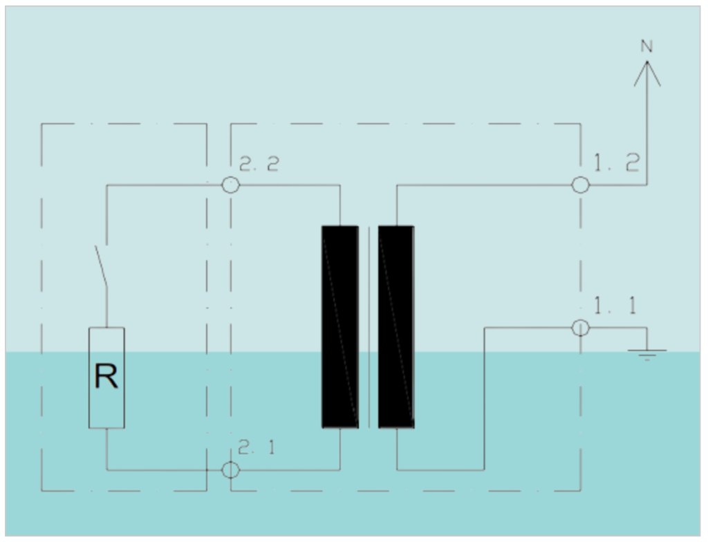
- NER connected to One-Phase Transformer: This type of NER is suitable for scenarios involving one-phase transformers, offering effective grounding and fault current management.
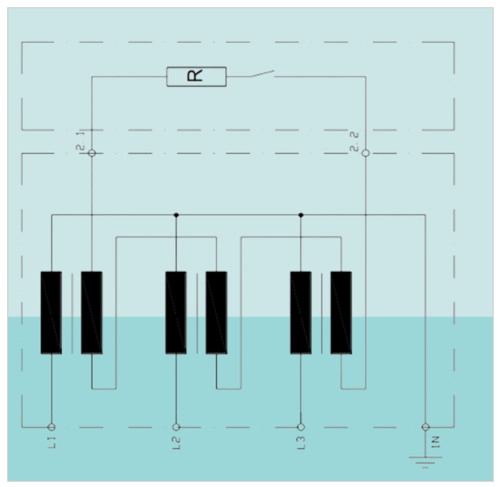
- NER connected to Grounding Transformer: Grounding transformers require specialized NERs to ensure safe and reliable operation. Swedish Neutral offers solutions designed to meet these specific needs.
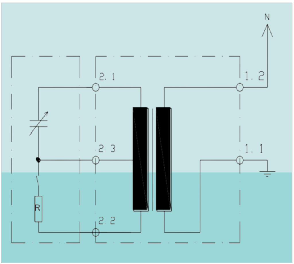
- NER connected to Arc Suppression Coil: In setups that incorporate arc suppression coils, dedicated NERs are essential to provide the required grounding and protection against fault currents.
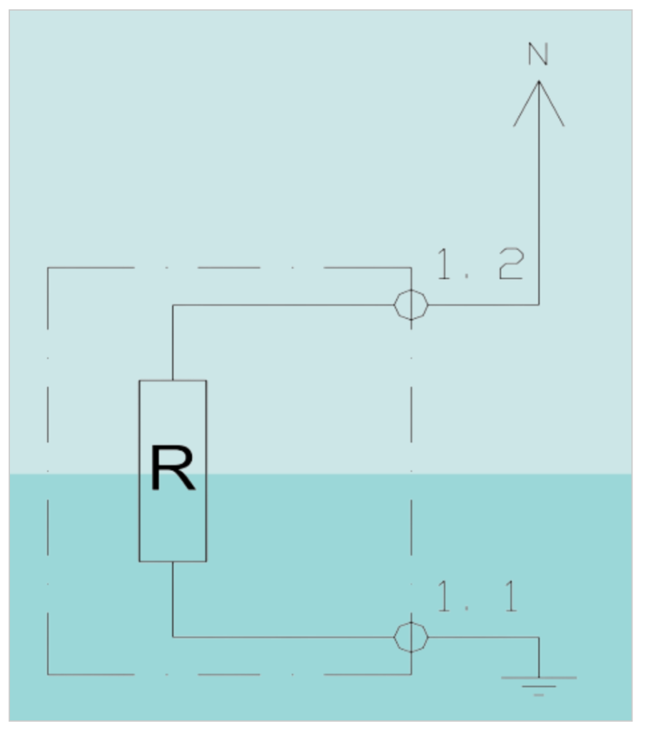
- Primary NER: Primary NERs are versatile solutions that can be applied in a wide range of electrical systems, enhancing safety and fault management across various configurations.
The importance of neutral grounding
Neutral grounding plays a critical role in ensuring the reliability, safety, and efficiency of electrical distribution systems. The importance of neutral grounding becomes evident when considering fault currents and transient over-voltage events, as these can have significant repercussions, including:
- Network Availability: Fault events can lead to the interruption of electricity supply, causing downtime and inconvenience for consumers and businesses alike.
- Equipment Costs: Faults can result in considerable damage to electrical equipment at the fault point, necessitating costly repairs or replacements.
- Premature Aging: Faults not only impact the immediate faulted equipment but can also lead to the premature aging of other connected distribution equipment, such as transformers, which can be a substantial financial burden.
- Safety Risk: Faults pose a heightened safety risk to personnel, as they can lead to hazardous conditions and potentially dangerous situations.
By implementing Neutral Earthing Resistors (NERs) within the distribution system and effectively controlling fault currents and transient over-voltages, several significant benefits can be realized:
- Damage Reduction: NERs help eliminate or reduce physical damage to equipment by effectively controlling fault currents and limiting their impact.
- Extended Equipment Life: With controlled fault currents, the life expectancy of connected distribution equipment, such as transformers, is extended, reducing the need for frequent replacements.
- Cost Savings: Reduced equipment damage and extended life translate to lower operation and maintenance expenses, providing cost savings in the long run.
- Faster Fault Isolation: NERs simplify and expedite the isolation and clearing of the original fault, minimizing downtime and disruptions.
- Enhanced Network Security: By mitigating fault-related risks, NERs contribute to improved network security and a reduction in unplanned shutdowns, ensuring a more reliable power supply.
In summary, neutral grounding, facilitated by NERs, is an essential element in modern electrical distribution systems, serving to enhance equipment protection, extend service life, reduce costs, and bolster overall network reliability and safety.
Neutral Earthing Methods:
Neutral earthing plays a vital role in various electrical applications and networks, and the choice of method depends on specific requirements and considerations. Here are some common methods of neutral earthing:
- High Resistance Grounding: This method is employed in commercial systems where continuous operation is essential even after a fault occurs. Neutral Earthing Resistors (NERs) are used to reduce fault current to a low value, typically 10 Amps or less, without tripping circuit breakers. Protection schemes are activated during a fault to locate and clear it swiftly, preventing major damage at this current level.
- Low Resistance Grounding: Large medium and high voltage electrical networks often utilize low resistance grounding. These NERs are designed to permit a controlled amount of fault current, ranging from 200A to 2500A, to flow. This level of current is adequate to activate protective devices but not sufficient to cause significant damage at the fault point.
- Solidly Earthed Grounding: Solidly earthed grounding is commonly applied in low voltage (600V or less) applications, where the neutral point is connected directly to earth. While these systems help mitigate transient over-voltages, they do not limit fault current during fault events.
When designing and sizing an NER, engineers consider various parameters, including the rated voltage, rated current (maximum cold current), duty rating (length of time the NER must tolerate rated current), short time rating (usually 10 or 60 seconds), continuous rating (typically 10% of full load current), insulation specifications based on line voltage, temperature rise limits, element type (metallic resistors are often preferred), IP rating for protection against environmental factors, enclosure material (stainless steel, mild steel, or aluminum), and optional ancillary items like vacuum contactors, current transformers, protection relays, and monitoring equipment.
Selecting the appropriate neutral earthing method and configuring the NER correctly are essential steps in ensuring the reliability, safety, and efficiency of electrical systems while protecting equipment and minimizing damage during fault events.
Neutral Earthing Resistor (NER) Selection Guide
Voltage, current, and time are critical factors in determining the specifications of neutral earthing resistors (NERs) and their performance in electrical systems:
Voltage: NERs are typically identified by the system voltage of the supply, such as “11kV NER.” However, the maximum voltage the resistor encounters in service is the line voltage (phase to neutral voltage). Consequently, the rating plate of the resistor indicates the line voltage. For instance, an “11kV NER” is rated at 6.35kV.
Current: NERs are rated based on the current at line voltage, implicitly specifying the resistance value. The current rating selection depends on various factors, including the system’s characteristics, equipment requirements, and protection relay system. For example, generator manufacturers may specify a tolerable maximum earth fault current, influencing the current rating choice. It is also influenced by the protection relay system’s capabilities, as newer systems can operate reliably at lower currents. In the absence of specific information, the current is often chosen to be equal to or lower than the rated current of the transformer or generator. Current values can range from tens of amps to thousands of amps.
Preferred current values are often selected from the ISO R’10 series, which is widely used across the electrical industry. Common values in this series include 10, 12.5, 16, 20, 25, 32, 40, 50, 63, 80, and 100 amps, along with multiples thereof. Additionally, multiples of 15, 30, 60, and 75 amps are also commonly used.
Time: NERs are typically rated to carry their current for a duration of 10 seconds. While the actual current flow duration is much shorter, the 10-second rating allows for the occurrence of multiple events. This can be beneficial when auto-reclosers are employed or when considering the operation of an upstream backup protection device in case of a protection relay failure. Some older specifications based on liquid resistors may specify longer durations of 30 seconds, reflecting the extended cooling time associated with that technology.
Read Also advance article of What are Neutral Grounding Resistors – Engineers Guide.