Neutral Grounding Resistors (NGRs) are essential components in electrical systems for grounding the neutral point of transformers and generators. They play a crucial role in electrical safety and system protection.
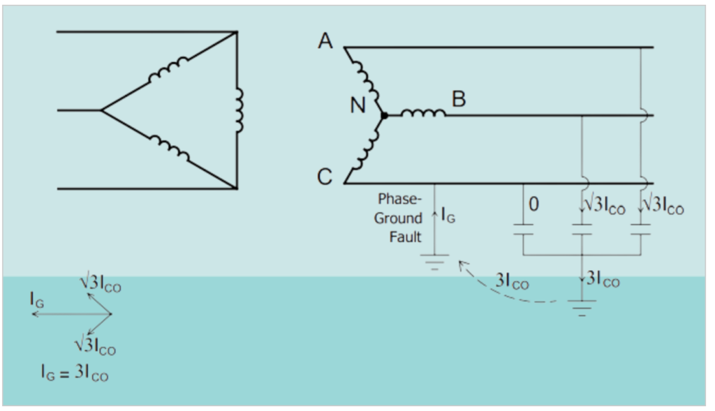
In an ungrounded electrical system, there is no direct intentional connection between the system conductors and ground. However, due to the inherent capacitive coupling between the conductors and ground, it effectively becomes a capacitance grounded system. This capacitive coupling primarily exists between individual conductors and ground, while the capacitance between phases has a lesser impact on the grounding characteristics and is usually disregarded.
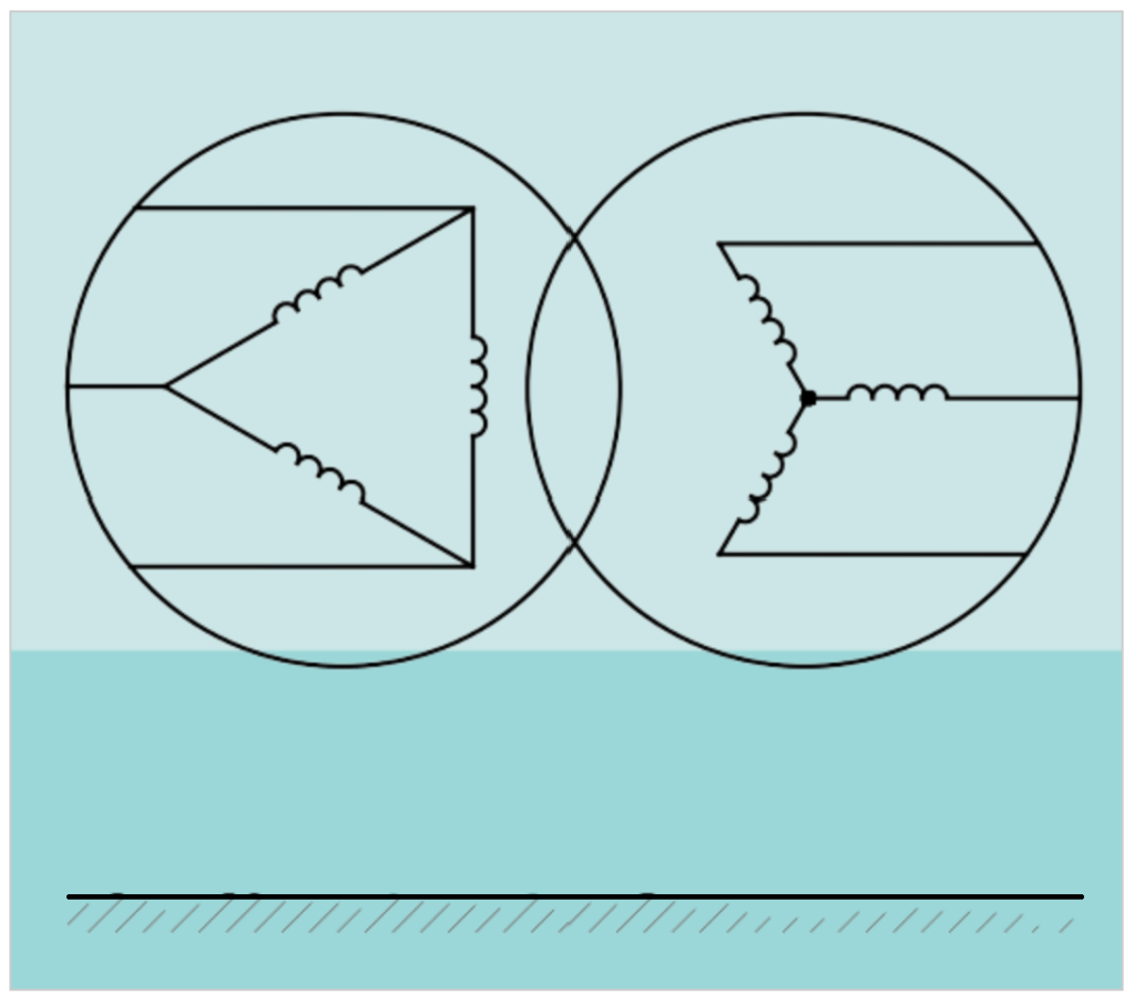
Initially, when the system is in a balanced and unfaulted condition, with balanced three-phase voltages applied to the lines, the distributed capacitive reactance to ground (Xco) is assumed to be balanced. Capacitive charging current (Ico) flows through each capacitor to ground and is 120° out of phase with each other. The phase voltages to ground are also equal and have a 120° phase displacement from one another.
However, if one of the system conductors, let’s say phase C, faults to ground, the current flow through that capacitance to ground ceases because there is no longer a potential difference across it. In response, the voltage across the remaining two distributed capacitors to ground increases from line to neutral to line to line. As a result, the capacitive charging current (Ico) in the two unfaulted phases increases by the square root of 3, and the line-to-ground voltages are no longer 120° apart but instead have a 60° phase displacement from each other.
One of the significant drawbacks of ungrounded systems is the potential for destructive transient overvoltages to occur throughout the system during restriking ground faults. These overvoltages, which can be several times the normal voltage magnitude, happen because of a resonance condition between the inductive reactance of the system and the distributed capacitance to ground.
These transient overvoltages pose a serious risk to the insulation of the electrical components and can lead to failures at multiple locations within the system. This is a key reason why ungrounded systems are no longer recommended, and grounded systems, in some form, have become the preferred choice in modern electrical systems. Additionally, locating the fault in an ungrounded system can be challenging and time-consuming, making it difficult to ensure the system’s continuity and reliability.
Neutral Grounded System Through a Resistance:
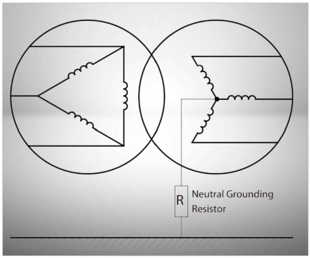
In a resistance-grounded electrical system, the neutral point of a transformer or generator is intentionally connected to the ground through a resistor. This resistor has a significantly higher electrical resistance compared to the system’s reactance at the location of the resistor. As a result, the line-to-ground fault current is predominantly limited by the resistance of the grounding resistor itself. This intentional limitation of fault current by resistance grounding serves several important purposes:
- Mechanical Stress Reduction: By limiting fault currents through resistance grounding, mechanical stresses in various components of the electrical system, such as transformers, motors, and cables, are reduced. High fault currents can subject these components to substantial mechanical forces, potentially causing damage or failure. Limiting fault currents helps protect the equipment and ensures its longevity.
- Electric-Shock Hazard Mitigation: Stray ground-fault currents can pose electric-shock hazards to personnel working on or near the electrical system. When fault currents are not properly controlled, there is a risk of dangerous ground-fault currents taking unpredictable paths through the ground, which can lead to electric-shock incidents. Resistance grounding helps contain fault currents within manageable levels, minimizing the risk of electric-shock hazards and enhancing personnel safety.
By implementing resistance grounding, these critical safety and equipment protection measures are achieved, making it an essential practice in electrical systems where limiting fault currents and safeguarding personnel and equipment are paramount concerns.
1. Low-Resistance Grounding
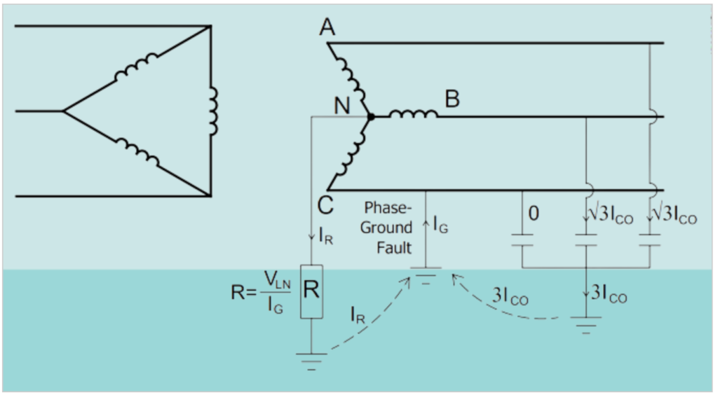
Low-resistance grounding is an intentional grounding method used in electrical systems to limit ground-fault currents within a specific range, typically between 100 Amperes (A) and 1000 A. This method involves connecting the neutral of a transformer or generator to the ground through a resistor, and the resistor’s value (denoted as R) is determined using the formula R = VIn/Ig, where:
- VIn represents the system’s line-to-neutral voltage.
- Ig is the desired ground-fault current, which can be determined based on regulatory standards or the specific requirements of the electrical system.
The primary objectives of low-resistance grounding are as follows:
- Selective Ground-Fault Clearing: Low-resistance grounding allows for the immediate and selective clearing of a grounded circuit in the event of a ground fault. This means that when a ground fault occurs, the system can quickly and precisely identify the faulted portion of the circuit and isolate it from the rest of the system. This selective clearing is essential for minimizing downtime and maintaining the reliability of the electrical system.
- Equipment Protection: Low-resistance grounding is employed to safeguard electrical equipment, such as transformers and generators, from damage caused by excessively high fault currents. By limiting the fault current to a controlled range, the risk of mechanical stresses and damage to equipment windings is significantly reduced.
- Overvoltage Limitation: This grounding method also helps limit transient overvoltages that can occur during ground faults. To further enhance overvoltage protection, surge arresters may be installed in parallel with the neutral resistance. Surge arresters are selected to provide voltage protection and are designed to safeguard the system from voltage surges.
Low-resistance grounding is typically applied in medium-voltage systems up to 36 kV. By maintaining ground-fault currents at lower levels, this method effectively minimizes equipment damage while ensuring the safety and reliability of the electrical system. The choice of low-resistance grounding parameters, such as the resistor’s value and the desired ground-fault current, is influenced by regulatory standards, system requirements, and equipment protection considerations.
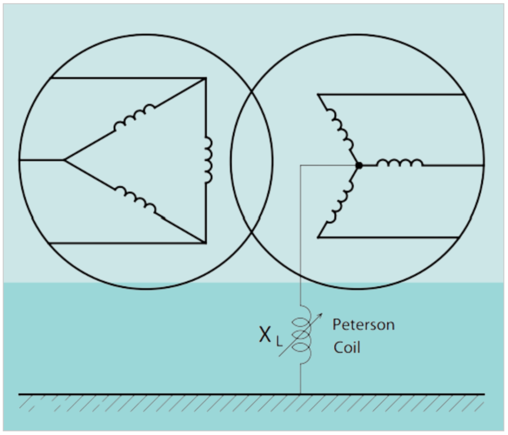
2. High-Resistance Grounding
High-Resistance Grounding (HRG) is a grounding method that utilizes a neutral resistor with a high resistance value. The primary purpose of this resistor is to limit the ground-fault current (Ig) to a level that is typically equal to or slightly higher than the total capacitance charging current (3 times Ico). HRG is often employed to limit the ground-fault current to 10 Amperes (A) or less, and this is particularly common in systems with generators rated up to 15 kV.
Resistor Value Selection: To determine the resistance value (R) of the neutral resistor in an HRG system, the following formula is used: R = Vln / Ig, where Vln represents the system’s line-to-neutral voltage and Ig is the desired ground-fault current. For instance, if you want to limit the ground-fault current to 10 A in an 11 kV generator, you would calculate it as follows: (11 kV / √3) / 10 A = 635 ohms. This means a 635-ohm resistor would be used in this scenario to achieve the desired ground-fault current limitation.
High-resistance grounding (HRG) is designed in such a way that it doesn’t require immediate disconnection or tripping of the system in the event of a ground fault. Instead, it focuses on detecting and signaling the presence of a ground fault, allowing for timely intervention and maintenance without disrupting the entire system. Here’s how HRG systems typically handle ground faults:
- Ground Fault Detection: When a ground fault occurs in a high-resistance grounded system, the faulted phase’s potential rises to approximately line-to-neutral voltage. This rise in voltage is detectable, and it indicates the presence of a ground fault.
- Grounding Transformer: In many HRG systems, a grounding transformer is connected to the neutral point of the system. This transformer typically operates under normal conditions when there are no ground faults, and the neutral point remains at zero potential.
- Overvoltage Relay (Relay 59): To monitor the neutral point and detect changes in potential due to ground faults, an overvoltage relay, often labeled as “59,” is used. This relay is designed to respond to voltage changes beyond a specified threshold.
- Step-Down Transformer: The line-to-neutral voltage of the system is typically higher than the voltage level acceptable to the overvoltage relay. To make the detected voltage changes more accessible for the relay, a step-down transformer is used to reduce the voltage level. Commonly, the voltage is lowered to 120 V or 230 V, which is suitable for the relay’s operation.
- Alarm and Notification: When the overvoltage relay detects a significant change in voltage associated with a ground fault, it triggers an alarm or notification. This alerts operators or maintenance personnel to the presence of a ground fault, allowing them to investigate and address the issue.
High-resistance grounding (HRG) offers several key advantages, making it a suitable choice for specific applications:
- Service Continuity: In HRG systems, the first ground fault does not require the shutdown of process equipment. This means that essential operations can continue running, minimizing downtime and ensuring uninterrupted service.
- Reduced Transient Overvoltages: HRG systems help reduce transient overvoltages that can occur during restriking ground faults. Lower overvoltages contribute to better equipment protection and system reliability.
- Ground Fault Location: HRG systems can incorporate signal tracing or pulse systems to facilitate the accurate detection and location of ground faults. This feature aids maintenance personnel in quickly identifying and addressing issues.
- Enhanced Safety: By limiting ground-fault currents to very low levels, HRG eliminates the flash hazards associated with high ground-fault currents. This enhances safety for personnel working on or near electrical systems.
- Simplified Protection: Unlike some other grounding methods that require coordinated ground-fault relaying, HRG systems typically rely on detection and alarm mechanisms. This simplifies the protection scheme and reduces the expense associated with coordination.
HRG is commonly used in systems with voltages up to 6.3 kV, where service continuity is a priority, and capacitive charging currents are manageable. It finds applications in industrial settings with no line-to-neutral loads.
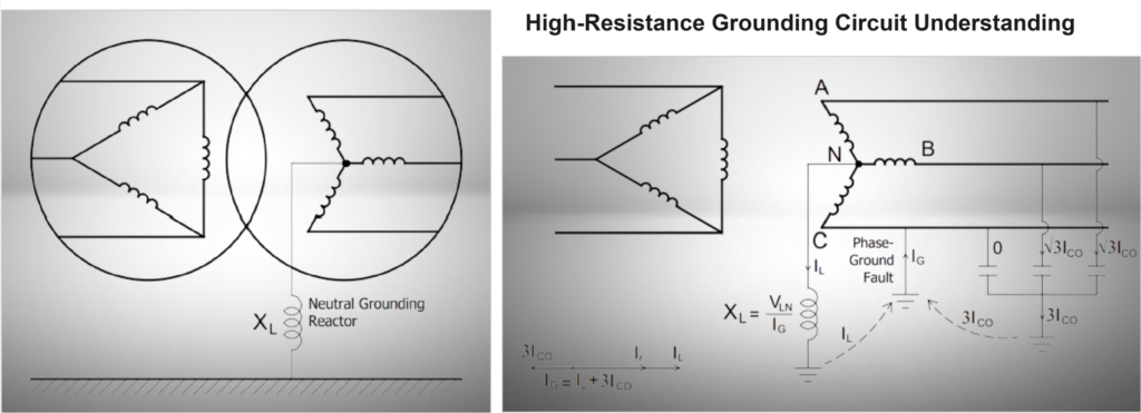
3. Neutral Grounded System Through a Petersen Coil
Reactance grounding is typically chosen for applications where the goal is to limit the ground-fault current to a level that is relatively close to the magnitude of a three-phase fault. In such cases, using neutral grounding reactors can often be a more cost-effective solution compared to grounding resistors, particularly when the desired ground-fault current magnitude is several thousand amperes.
This choice of grounding method becomes particularly relevant in scenarios where large substations supply power to medium-voltage distribution systems. In these situations, the total zero-sequence impedance of the step-down transformers within the substation can cause the single line-to-ground-fault current to significantly exceed the magnitude of a three-phase fault. When this occurs, there is a desire to limit the ground-fault current to more manageable levels while keeping the total fault current within reasonable limits.
These conditions are most commonly encountered in electric utility distribution practices, where ensuring safe and efficient fault protection is of paramount importance. By utilizing reactance grounding with neutral grounding reactors, it becomes possible to strike a balance between minimizing fault currents and maintaining overall system reliability and stability. This approach helps prevent excessive stress on equipment and ensures the safety of both the electrical system and personnel working with it.
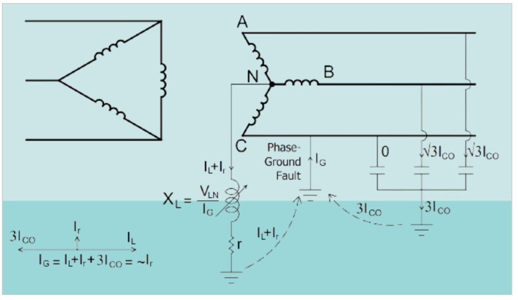
Grounding through a Petersen coil, also known as a ground fault neutralizer or compensation, involves the use of a reactor connected between the neutral of an electrical system and the ground. This reactor, denoted as XL, is carefully chosen or “tuned” to resonate with the distributed capacitance of the system, denoted as Xco. The goal of this tuning is to create a ground-fault current that is resistive and low in magnitude. Additionally, a resistance, represented as “r,” is included in the setup to account for reactor losses.
The result of this grounding configuration is a ground-fault current that is in phase with the line-to-neutral voltage, causing current zero and voltage zero to occur simultaneously. This type of grounding system is relatively rare in many electricity distribution networks around the world. One reason for its limited use is that the resonant circuit, which includes the Petersen coil, requires readjustment if there are changes in the system’s parameters. Any alterations to the system, such as modifications in capacitance or other factors, would necessitate recalibrating the Petersen coil to maintain effective fault protection. As a result, this grounding method is more complex and less commonly employed compared to other grounding techniques.
4. Solidly Grounded System or Solidly Earthed
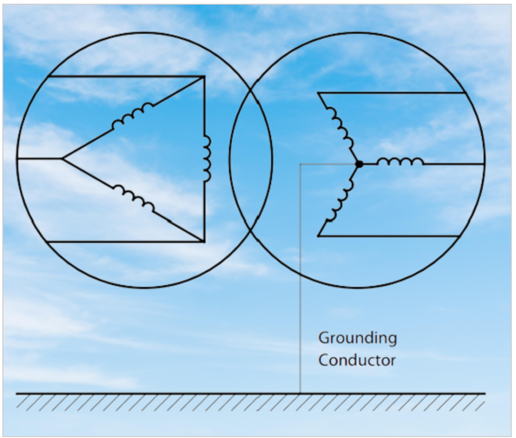
Solid Earthed refers to the practice of directly connecting a system conductor, typically the neutral of a generator, power transformer, or grounding transformer, directly to the ground without any intended impedance in the connection. However, it’s important to consider both the impedance of the power source and any unintentional impedance introduced in the grounding connection when assessing the effectiveness of this grounding method.
Solid Earthed is typically utilized when the magnitude of the single-phase earth fault current in the system is at least 60% of the three-phase fault current. This means that a substantial portion of the fault current is being directed to the ground during a fault event.
It’s worth noting that even in solid grounding, there may be some impedance due to the reactance of the generator or transformer that is in series with the neutral circuit. This means that a solid connection doesn’t create a completely zero-impedance circuit. The effectiveness of this grounding method depends on factors like the ratio of system zero-sequence reactance to system positive-sequence reactance. If this ratio is too high, it may not achieve the desired objectives of grounding, which include protection against transient overvoltages and the suppression of voltage to ground on the unfaulted phases. Therefore, the design and implementation of solid grounding must carefully consider these factors to ensure the desired outcomes.
The potential issues mentioned, where the zero-sequence impedance of the grounded source exceeds the effective positive-sequence impedance of multiple sources in parallel, are more likely to occur in specific situations rather than typical industrial and commercial power systems.
One of these scenarios is when a power system is supplied by multiple generators and/or transformers operating in parallel. In such cases, if the neutral of only one source is grounded (Solid Earthed), it is possible for the zero-sequence impedance of the grounded source to become significantly higher than the effective positive-sequence impedance of the other sources in parallel. This imbalance can lead to unintended consequences in terms of fault current distribution and system behavior.
Solid Earthed is typically recommended for use in low-voltage systems below 600 volts, where the fault currents associated with solidly grounded systems are within acceptable limits. It may also be considered for high-voltage systems above 36 kV. However, in situations involving multiple parallel sources, careful evaluation and analysis of the grounding method and impedance characteristics are necessary to ensure the safe and reliable operation of the power system.
Grounded System Through a Transformer:
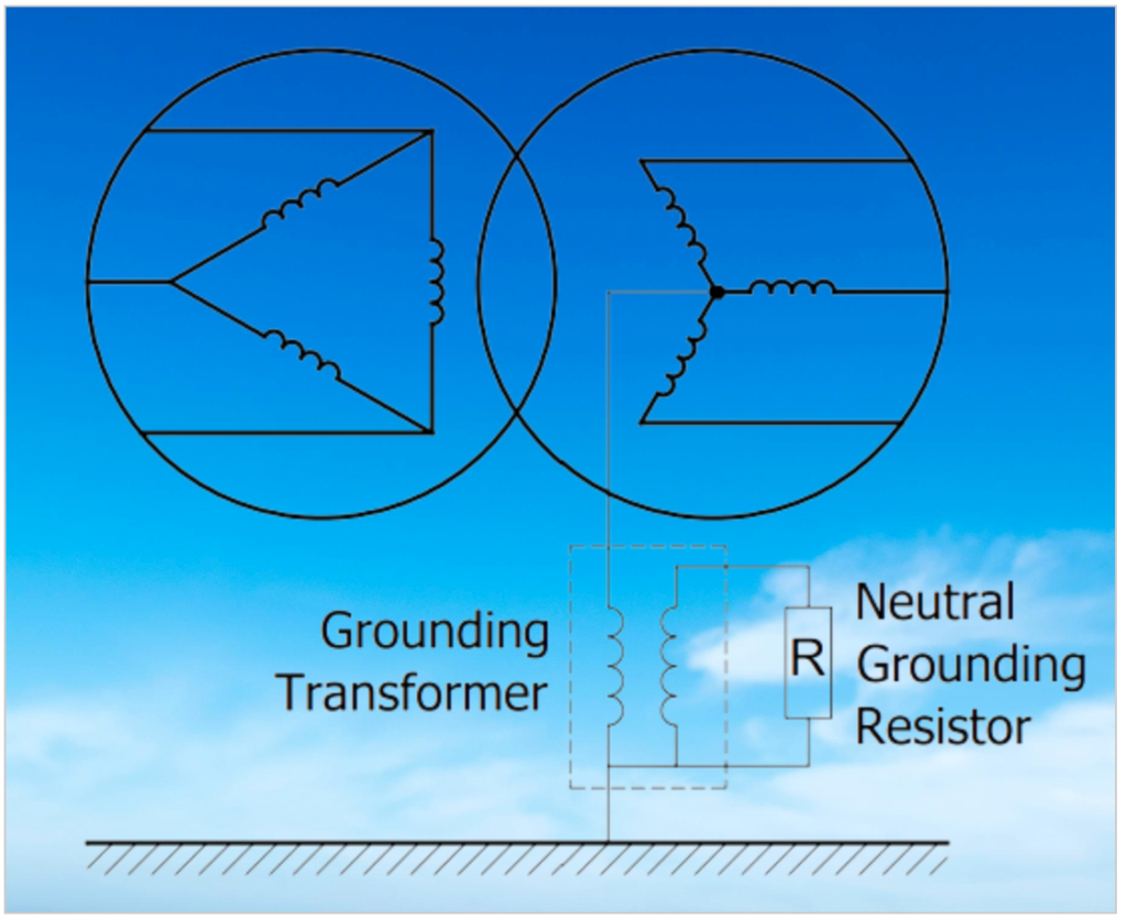
1. Neutral Grounded System Through a Single Phase Transformer and a Resistor
The neutral grounded system through a single-phase transformer and a resistor is a grounding method commonly used for generators. This system behaves like a non-grounded system under normal conditions but effectively limits fault currents in the event of a phase-to-ground fault.
Here’s how it works:
- Components: This system consists of two main components: a grounding transformer and a neutral grounding resistor.
- Grounding Transformer: The primary winding of the grounding transformer is connected to the neutral winding of the generator or system. The secondary winding of the grounding transformer is used to connect the neutral grounding resistor.
- Fault Current Limitation: When a phase-to-ground fault occurs, the grounding transformer limits the fault current to a value usually less than 15 A on the primary side of the transformer. This limitation is designed to minimize the damage caused by fault currents.
- System Behavior: Under normal operating conditions, this grounding system behaves similarly to a non-grounded system. However, in the event of a fault, it effectively limits the fault current and prevents excessive damage.
- Fault Duration: Typically, the fault duration in this system is set to around 1 minute, which is a common practice for high-resistance neutral grounding.
- Voltage Ratings: The primary voltage rating of the grounding transformer matches the phase-neutral voltage of the system or generator. The secondary voltage rating is usually lower, often designed as 240 V or 120 V. Using a lower secondary voltage helps reduce the size and cost of the neutral grounding resistor because it doesn’t need to withstand the higher phase-neutral system voltage.
This grounding method offers a good balance between normal system operation and fault protection. It ensures that in the event of a fault, the fault current is limited to a safe level, preventing extensive damage and ensuring the continuity of the system. Additionally, by using a lower secondary voltage for the resistor, cost savings are achieved while maintaining effective fault protection.
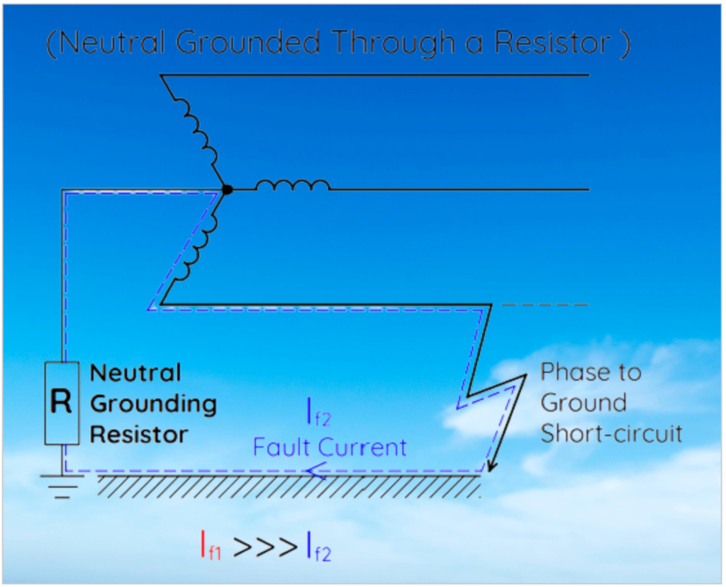
2. System Neutral Obtaining with Zig-zag Transformer
A Zig-zag transformer, also known as a zigzag grounding transformer, is employed in delta-connected electrical systems to create an artificial neutral point when a true neutral point is unavailable or inaccessible. This allows the system to be grounded effectively. Here’s how it works:
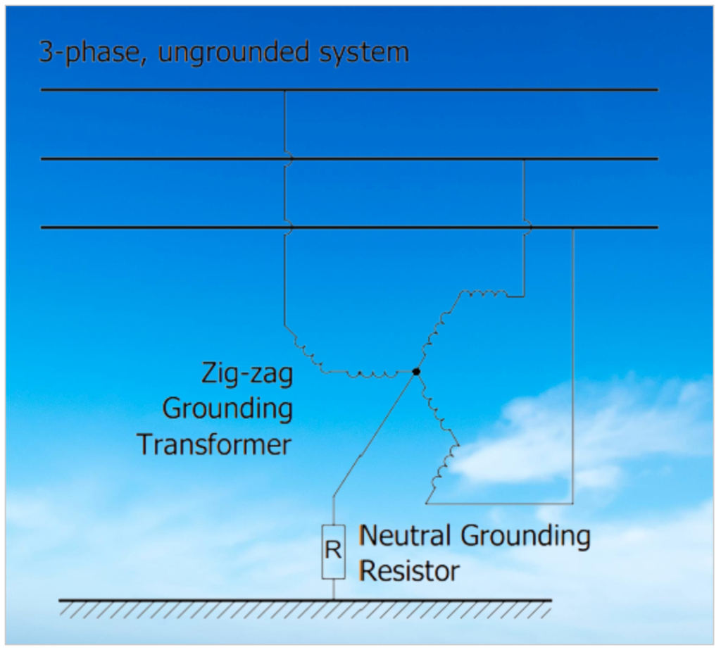
- Delta-Connected System: In some electrical systems, particularly delta-connected ones, there may be no true neutral point. In such cases, grounding the system can be challenging. Zig-zag transformers are used to address this issue.
- Transformer Design: Zig-zag transformers are specifically designed for grounding purposes. They are typically built to withstand fault currents for a short duration, usually around 10 seconds. This design allows them to be smaller and more cost-effective than continuously rated three-phase transformers of the same power rating.
- Winding Configuration: In a Zig-zag transformer, each phase consists of six windings, with two windings per phase connected in reverse phase. This configuration creates a high impedance for the phase currents, helping to limit fault currents.
- Zero-Sequence Impedance: While Zig-zag transformers provide high impedance to phase currents, their impedance to zero-sequence voltages is relatively low. This means that they allow high ground-fault currents to flow effectively.
- Current Division: The Zig-zag transformer plays a crucial role in dividing the ground-fault current into three equal components. These currents are in phase with each other and flow through the three windings of the grounding transformer.
- Neutral Point Creation: Zig-zag transformers do not have a secondary winding like typical transformers. Instead, they create a neutral point through the Wye (star) configuration of their windings. This artificial neutral point can be grounded effectively using a resistor or other grounding methods.
Overall, the Zig-zag transformer is a valuable component in electrical systems where creating a neutral point for grounding is essential. It allows for effective ground fault current handling and provides a reliable means of grounding in systems that lack a natural neutral point.
3. System Neutral Obtaining with Wye-Delta Transformer
A Wye-Delta connected three-phase transformer or transformer bank can also be used for system grounding. This configuration involves connecting the primary phase windings to the phases of the electrical system, with the neutral point being connected directly or through a resistance to the ground. Here’s how it works:
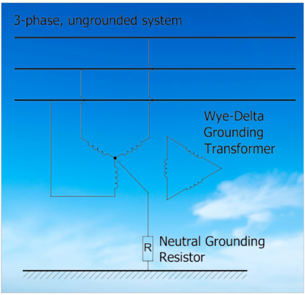
- Transformer Connection: In a Wye-Delta grounding transformer setup, the primary windings of the transformer are connected in a Wye (star) configuration to the phases of the electrical system. The secondary winding is connected in a Delta configuration.
- Grounding Path: The primary purpose of this setup is to provide a path for ground fault current when a phase-neutral fault occurs in the system. In the event of a fault, the fault current flows through the grounding transformer.
- Fault Current Limitation: The fault current is limited to the sum of the transformer’s leakage reactance and the neutral resistance. This limitation is due to the transformer having zero-sequence impedance in the primary Wye windings, and the secondary Delta connection forms a closed series circuit.
- Voltage Rating: The voltage rating of the Wye winding should not be less than the normal line-to-line system voltage to ensure compatibility and effective grounding.
- Installation: The Wye-Delta grounding transformer should be connected between the secondary terminals of the system’s power transformer and the main circuit breaker. It is advisable to install it as close as possible to the power transformer for efficient fault current diversion.
- Multiple Transformers: In systems with multiple power transformers, a separate grounding transformer should be connected for each transformer. However, it is essential to ensure that there is only one earthing transformer in the same section or branch of the system. This prevents potential conflicts and ensures proper grounding.
Overall, the Wye-Delta grounding transformer configuration serves as an effective means of providing grounding in electrical systems, particularly when multiple transformers are involved. It limits fault currents, enhances safety, and helps maintain the integrity of the electrical distribution network.
4. System Neutral Obtaining with Wye – Open Delta Transformer
In the Wye-Open Delta transformer configuration for obtaining a system neutral, the neutral side of the primary winding is directly connected to the ground. Additionally, a limiting resistor is linked to the open ends of the secondary windings in the open delta connection. This resistor plays a crucial role in limiting the current within the closed secondary delta windings when a phase-earth fault transpires within the system. Consequently, this arrangement effectively constrains the fault current within the primary windings of the earthing transformer.
Neutral Grounding Resistor:
In both low-voltage (LV) and medium-voltage (MV) distribution networks, the grounding of neutral points in power transformers and generators is achieved through the use of a resistor. The primary objectives of Neutral Grounding are as follows:
- Limit Ground Fault Current: The primary purpose is to restrict the magnitude of ground fault current. By doing so, it aims to prevent any damage to the transformer and generator while ensuring the continuity of their operation and overall safety.
- Enable Fault Current Sensing: The inclusion of current transformers within the Neutral Grounding Resistor facilitates the sensing of fault currents by relays. This is crucial for limiting the duration of faults and mitigating oscillating and non-oscillating transient voltage, which can otherwise endanger the insulation levels of system equipment.
- Enhance Personnel Safety: Maintaining safe step voltages on-site is essential for safeguarding personnel working with the equipment. Neutral grounding aids in achieving this by preventing unsafe voltage levels during ground faults.
- Prevent Overheating and Mechanical Stress: Ground faults can lead to overheating and mechanical stress on equipment. Neutral grounding helps alleviate these issues by limiting the fault current magnitude.
The phase-ground short-circuit current of the transformer or generator serves as the basis for calculating the limiting current requirement of the neutral grounding resistor. The resistor’s design is such that it restricts the fault current to a level typically set at 10% of the calculated short-circuit current. In situations where the short-circuit current cannot be accurately calculated, the limiting current may be chosen up to the rated current. This selection must be optimized to ensure the relays can detect and respond to the designated fault current level effectively. Therefore, the primary rating of the current transformers installed on the neutral grounding resistor may differ from the limited fault current value.

The fault duration in neutral grounding systems typically ranges from 5 to 10 seconds. In some cases, such as facilities where sudden power interruptions are intolerable, fault durations can be extended up to 30 seconds. This is particularly relevant for critical establishments like hospitals, data centers, textile plants, cement plants, and manufacturing facilities that rely on continuous processes. In these scenarios, it’s essential to ensure that the fault current does not damage the system, enabling uninterrupted operation and the precise determination of the fault point without any power interruptions. For more detailed information on such systems, you can refer to the “High-Resistance Neutral Grounding System.”
To prepare an offer for a neutral grounding resistor, the following basic parameters and a single-line scheme of the system, if available, are required:
- Phase Voltages: Information about the phase-to-phase and phase-to-neutral voltages of the transformer or generator to which the resistor will be connected is essential.
- Fault Current Level: The magnitude of the fault current during ground faults is a critical parameter. It is necessary to determine the appropriate rating and characteristics of the neutral grounding resistor.
- Fault Duration: Knowledge of the expected fault duration is crucial for designing the resistor and protective measures accurately.
Having these details allows for the proper design and specification of the neutral grounding resistor to meet the specific needs of the system while ensuring safety and operational continuity.
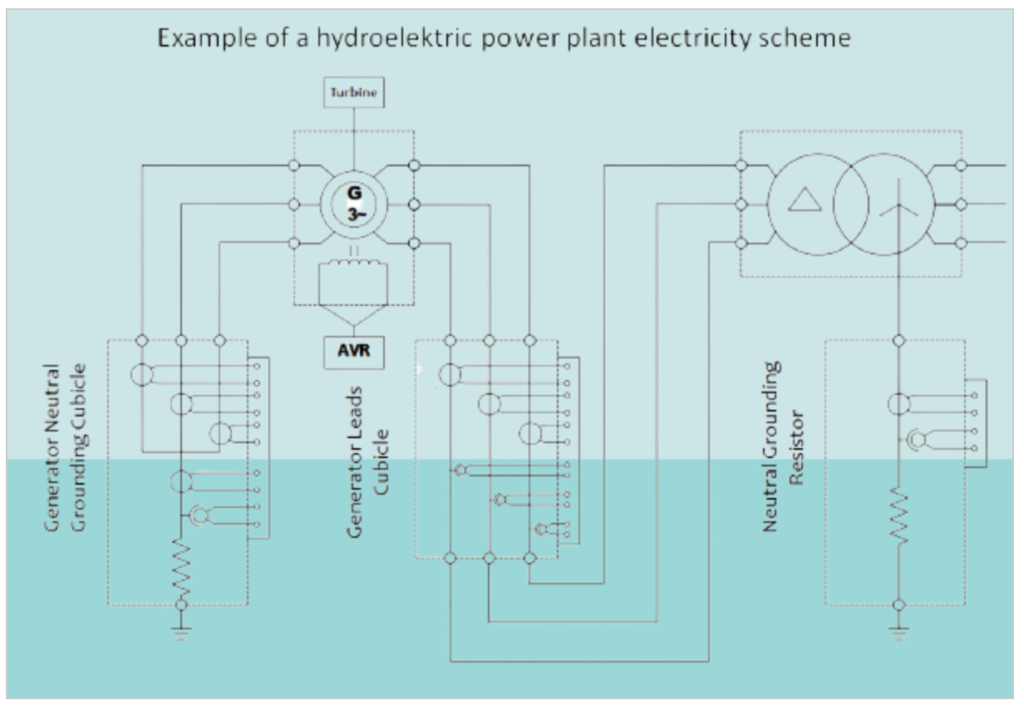
Generator Neutral Cubicle & Generator Leads Cubicle:
The Generator Neutral Cubicle and Generator Leads Cubicle are integral components within power generation systems, playing pivotal roles in ensuring the efficient and safe operation of generators. In the Generator Neutral Cubicle, the consolidation of three phases from both Low Voltage (LV) and Medium Voltage (MV) generators is carried out to establish a neutral point. This neutral point is then connected to the ground through a resistor, serving the crucial purpose of neutral grounding. What sets the Generator Neutral Cubicle apart is its capacity for real-time monitoring of 3-phase currents, providing valuable insights into current levels and aiding in fault detection and system protection.
High-Resistance Neutral Grounding System
High-Resistance Neutral Grounding Systems (HNGR) serve as critical components in various industrial facilities, including hospitals, data centers, textile plants, and cement plants, where uninterrupted operations are paramount. These systems are specifically designed to limit fault currents to a range of 5 to 10 amperes, ensuring the continuity of the electrical system. What sets HNGR apart is its capability to withstand fault currents continuously, even in the presence of capacitive and leakage currents stemming from cable capacitance.
In the realm of medium voltage systems, ranging from 400 V to 6.9 kV, HNGR systems shine as optimal solutions. A standout feature of HNGR systems is their ability to detect fault locations. When a phase-to-earth fault occurs within the network, the HNGR system responds by automatically halving the resistance value, causing the fault current to momentarily double, for instance, from 5A to 10A. This intentional change in current facilitates easy detection using a simple clamp meter, aiding in pinpointing the location of the fault. This automatic fault detection capability sets HNGR systems apart, displaying not only the fault’s distribution point but also the specific load connected to that point.
Furthermore, HNGR systems incorporate continuous monitoring mechanisms to ensure system functionality. In the event of a system failure, visual and audio alarms promptly alert users, enhancing both operational safety and system reliability. With these advanced features, HNGR systems provide essential support to critical industrial operations, safeguarding against unexpected interruptions and enabling rapid response to faults for a more robust electrical infrastructure.
Neutral Resistor Monitoring System:
The Neutral Resistor Monitoring System is a crucial component used in conjunction with monitoring relays, particularly continuity relays. These relays are responsible for identifying loose or broken connections within devices that restrict phase-to-ground fault currents, such as neutral grounding resistors, high-resistance neutral grounding systems, and generator neutral cubicles.
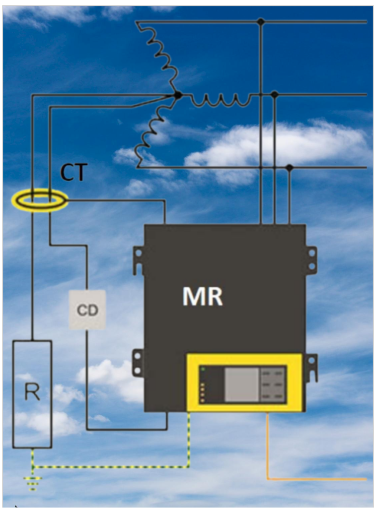
The system involves connecting one terminal of a sensing resistor to the neutral point, which passes through a parallel-connected neutral current transformer along with the neutral resistor. The other terminal of the sensing resistor is linked to the monitoring relay. The monitoring relay then transmits a low-amplitude, high-frequency signal to the neutral resistor via the sensing resistor. It measures the current and voltage at the neutral point, allowing for continuous monitoring of the resistance of the neutral grounding resistor. If the resistance deviates from the preset value, the system triggers a warning and/or trip signal.
Sensing resistors are manufactured and tested to meet the specific requirements of the network and monitoring relay. They come with various technical specifications, including suitability for voltages up to 110/√3 kV, fault currents up to 5000 A, and resistance materials made of stainless steel capable of withstanding extreme environmental conditions. The design features internal current transformers for detecting failure currents and adheres to ANSI-IEEE 32 standards and special specifications.
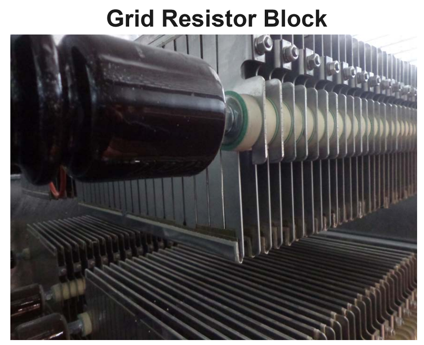
The resistor element itself can take the form of spring-wound, edge-wound, or grid resistor elements designed to accommodate the nominal current. These elements are fully modular, employing stainless steel bolt connections to ensure electrical continuity and withstand high temperatures and currents. Special design considerations are given to insulation, mechanical resistance, and the ability to dissipate thermal and mechanical effects resulting from overcurrent.

The enclosure housing the monitoring system is designed with a focus on protection and practicality. It typically meets IP23 standards for outdoor use, with an IP65 terminal box. The enclosure is made of standard hot-dipped galvanized steel and features a fully modular, rigid design with resistor blocks mounted for easy lifting and maintenance. It includes a lockable door, corrosion-resistant handling rings and connectors, as well as stainless steel product and warning labels for added durability and safety.