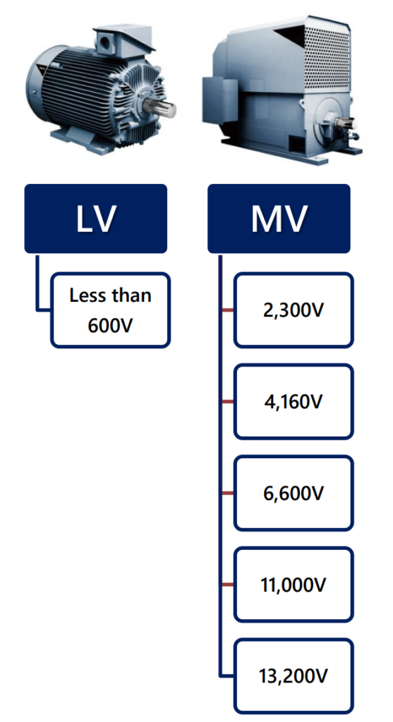
The article emphasizes the importance of a systematic approach for the safe and reliable application of medium voltage (MV) motors, which are commonly used in various industrial applications such as compressors, pumps, fans, extruders, and mills. The scope of the tutorial covers MV motors with voltages exceeding 2.3 kilovolts (kV) and motor power ranging from 500 horsepower (HP) to a substantial 100,000 HP.
Medium Voltage (MV) Motors Complete Technical Guide:
![Medium Voltage (MV) Motors What are they? Technical Guide [PDF]](https://paktechpoint.com/wp-content/uploads/2023/09/image-226-1024x367.png)
What is an Induction Motor or a Synchronous motor?
An Induction Motor and a Synchronous Motor are two common types of electric motors used in various industrial and commercial applications:
- Induction Motor:
- An induction motor is the most common type of industrial motor, making up over 99% of industrial motor applications.
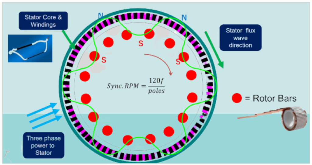
- It operates on the principle of electromagnetic induction, where electrical energy is transferred to the rotor (rotating part) of the motor through electromagnetic fields generated by the stator (stationary part).
- Induction motors typically run at speeds slightly less than their synchronous speed, resulting in what is known as “slip.” The synchronous speed is determined by the frequency of the power supply and the number of motor poles.
- These motors are often referred to as “squirrel cage motors” due to their rotor’s resemblance to a squirrel cage wheel. They are known for their simplicity, durability, and reliability.
- Induction motors are widely used in various applications, including pumps, fans, conveyors, and many industrial machines.
- Synchronous Motor:
- A synchronous motor is another type of electric motor that operates at a constant and precisely controlled speed, known as the synchronous speed. This speed is directly proportional to the frequency of the power supply and is not affected by load variations.
- Unlike induction motors, synchronous motors do not exhibit slip and maintain a fixed speed regardless of the load.
- Synchronous motors are often used in applications where maintaining a constant speed is critical, such as in power generation, synchronous clocks, and precision machinery.
- They are more complex and less common than induction motors and may require additional control systems to synchronize with the power supply frequency.
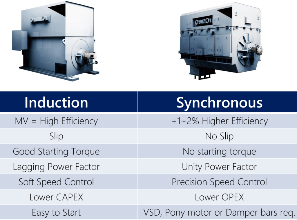
Key Differences between Induction & Synchronous Motors.
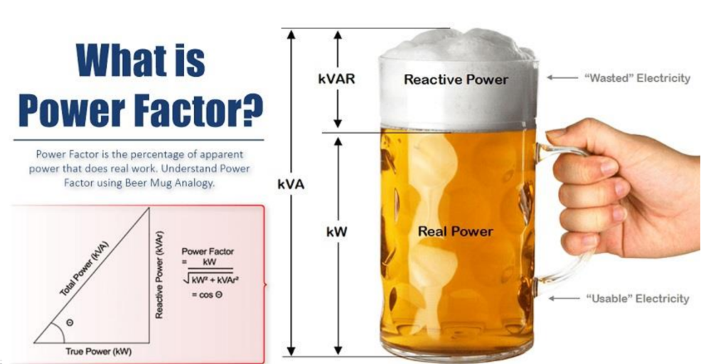
What is Power Factor for MV Motor?
Power Factor (PF) is a key electrical parameter that measures the efficiency of electrical power utilization in an AC (alternating current) circuit. It is expressed as a dimensionless number between 0 and 1 or as a percentage between 0% and 100%. Power factor indicates how effectively electrical power is being converted into useful work output in an electrical system.
In an AC circuit, power is composed of two components:
- Real Power (P): Real power is the component of power that performs useful work in the circuit, such as driving motors, heating elements, or powering electronic devices. It is measured in watts (W).
- Reactive Power (Q): Reactive power is the component of power that does not perform useful work but is required to maintain the voltage levels and magnetic fields in the circuit. It is necessary for inductive and capacitive loads and is measured in volt-amperes reactive (VAR).
Power Factor is defined as the ratio of real power (P) to apparent power (S), where apparent power is the vector sum of real power and reactive power:
Power Factor (PF)=P / S
Power Factor can also be expressed as:
PF= Real Power (W) / Apparent Power (VA)
Here are key points about Power Factor:
- A Power Factor of 1 (or 100%) indicates that all the electrical power is being used for useful work, and there is no reactive power. This is ideal and represents maximum efficiency.
- A Power Factor less than 1 (typically expressed as a decimal) indicates that a portion of the electrical power is being used for non-productive purposes (reactive power), which can result in energy losses and inefficiency in the electrical system.
- Low power factor can lead to increased current levels, voltage drop, and higher energy costs for utilities and consumers.
- Power factor correction techniques, such as adding power factor correction capacitors, are used to improve power factor and reduce inefficiencies in electrical systems.
- Power Factor is an essential consideration in industrial and commercial settings, as utilities often charge penalties for low power factor to encourage efficient power usage.
Power Factor is a critical parameter in electrical engineering that quantifies the efficiency of electrical power utilization. It helps assess how effectively electrical energy is converted into useful work and is an important factor in managing energy efficiency and reducing electricity costs.
MV Motor Voltages:
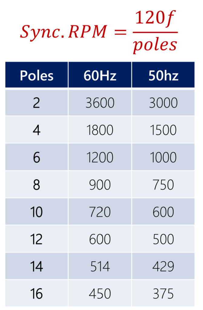
What is Poles & Speed in Medium Voltage Motors?
In the context of medium voltage motors, “poles” and “speed” are fundamental characteristics that describe the motor’s design and performance. These parameters play a crucial role in understanding how a medium voltage motor operates. Here’s an explanation of both terms:
- Poles:
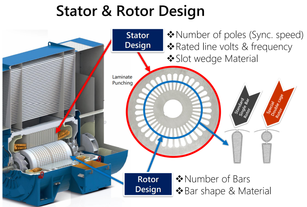
- In a medium voltage motor, “poles” refer to the number of magnetic poles present in the stator (the stationary part) of the motor. These poles are created by the arrangement of winding coils and are a key factor in determining the motor’s speed and performance characteristics.
- The number of poles directly affects the motor’s synchronous speed, which is the speed at which the motor will rotate when it operates at its rated frequency (typically 50 Hz or 60 Hz).
- Motors with more poles tend to have a lower synchronous speed, while motors with fewer poles have a higher synchronous speed. For example, a motor with four poles will have a lower synchronous speed than a motor with two poles.
- The number of poles also influences the torque characteristics of the motor. Motors with more poles tend to have higher torque at lower speeds, making them suitable for applications that require high starting torque.
- Speed:
- The “speed” of a medium voltage motor refers to its rotational speed, typically measured in revolutions per minute (RPM). The speed of the motor depends on various factors, including the number of poles, the frequency of the power supply, and the motor’s load.
- The synchronous speed of a motor is given by the formula:
Synchronous Speed (RPM)=120×Frequency (Hz)/ Number of Poles
- However, in practical applications, the motor’s actual speed is usually slightly less than the synchronous speed due to slip. Slip is a small difference between the synchronous speed and the actual rotor speed, which occurs when the motor is loaded. The slip allows the motor to develop torque and overcome inertia during startup.
- The speed of a medium voltage motor is a critical parameter in selecting the right motor for a specific application. Different applications may require motors with varying speeds to meet their operational requirements.
“Poles” in a medium voltage motor refer to the number of magnetic poles in the stator, which affects the synchronous speed and torque characteristics of the motor. “Speed” refers to the actual rotational speed of the motor, influenced by the number of poles, frequency, and load conditions. These parameters are essential for matching the motor to the requirements of a particular application.
The terminology used in the motor industry can sometimes be specific and unique to the field.
- Number of Poles: In motor terminology, the “number of poles” indeed refers to the configuration of the motor’s stator windings, resulting in the creation of magnetic poles. Each pole represents a pair of North and South magnetic poles. The number of poles directly affects the motor’s synchronous speed, as mentioned earlier.
- Synchronous Motors: Synchronous motors are designed to run precisely at their synchronous speed when connected to a power supply with a fixed frequency. The synchronous speed is determined by the number of poles and the power supply frequency. Synchronous motors are used in applications where maintaining a constant and precise speed is critical.
- Induction Motors: Induction motors, on the other hand, are designed to run at speeds slightly less than their synchronous speed. This speed difference is referred to as “slip.” Induction motors are the most common type of motor and are used in a wide range of applications due to their robustness and ability to handle varying loads. They are sometimes called “asynchronous motors” because their speed is not perfectly synchronized with the power supply frequency.
Medium Voltage Motors Standards:
In North America, medium voltage motor standards are primarily governed by NEMA MG1, which influences IEC metric dimensions. API standards like API 541, API 547, and API 546 are used for motors in industries like petrochemicals. Hazardous location standards include NEC 501 in the U.S. and NEC 505 in Canada, which aligns more with IEC standards. These standards ensure motor safety and reliability in various applications, particularly in hazardous environments.

Induction motors have some notable characteristics and limitations:
- Size Limit: Induction motors are typically limited in size to about 30,000 horsepower (HP). Beyond this range, other types of motors, such as synchronous motors, are often preferred for their performance characteristics.
- Efficiency: Induction motors are generally less efficient than synchronous machines, especially at higher power ratings. This means they may waste more energy as heat during operation.
- Power Factor (PF): The power factor of an induction motor is typically less than 1.0, indicating that there is some reactive power associated with its operation. This can affect the overall efficiency of the electrical system.
It’s important to note that these limitations are not due to technical constraints but rather practical considerations. Induction motors are well-suited for a wide range of applications, particularly in lower to medium power ratings, where their efficiency and power factor are acceptable. However, for very high power applications where efficiency is crucial, other motor types like synchronous motors may be preferred.
Synchronous motors are favored for large horsepower (HP) applications and have seen an increase in their applicable power range over the years. Here are some key points about synchronous motors:
- Large HP Machines: Synchronous motors are more commonly used in applications involving large HP ratings. While 30 years ago, “large” machines might have been around 5,000 HP, today synchronous motors are applied in the range of 30,000 HP to even 100,000 HP, thanks to advancements in motor technology.
- Unity Power Factor: Synchronous motors operate at a power factor of 1.0, which means they have a balanced relationship between real power and reactive power. This makes them highly efficient in terms of power utilization.
- Rotor Magnetization: Synchronous motors have their rotors magnetized to align with the stator’s magnetic field. Unlike induction motors, which rely on induction to create rotor currents, synchronous motors require magnets on the rotor to maintain synchronism with the stator’s rotating magnetic field.
- Permanent Magnet Motors: Some synchronous motors use permanent magnets on the rotor, which eliminates the need for excitation from an external source. These are referred to as permanent magnet motors and are known for their high efficiency and reliability.
Synchronous motors are well-suited for applications where precise control of speed and power factor is essential, making them ideal for large industrial machines and systems that demand high performance and efficiency.
Similarities in Induction & Synchronous:
Induction and synchronous motors share several similarities in certain aspects of their construction and associated accessories:
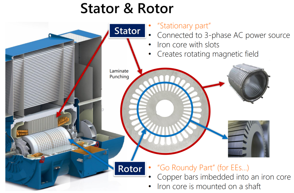
- Stator: Both types of motors have near-identical stator configurations. The stator is a stationary part of the motor responsible for generating a rotating magnetic field that interacts with the rotor to produce motion.
- Insulation Systems: Induction and synchronous motors use similar insulation systems to protect the motor windings from electrical stress and environmental factors. High-quality insulation is crucial for motor reliability.
- Enclosures: Both types of motors can be housed in similar types of enclosures, which provide protection against dust, moisture, and other environmental factors. Enclosures help ensure the motor’s durability and safety.
- Common Accessories: Both induction and synchronous motors can be equipped with common accessories for monitoring and protection, including:
- Space Heaters: Space heaters are used to maintain a minimum temperature within the motor to prevent condensation and moisture buildup during standby periods.
- Bearing and Winding RTDs (Resistance Temperature Detectors): RTDs are temperature sensors that monitor the temperature of motor bearings and windings. They provide important data for motor protection and maintenance.
- Differential Protection: Differential protection schemes are employed to detect internal faults in the motor windings by comparing the current entering and leaving the motor.
While these similarities exist, it’s important to note that induction and synchronous motors also have distinct differences in terms of their operating principles, rotor construction, and applications. Understanding both the commonalities and differences is crucial when selecting and maintaining motors for specific industrial or commercial applications.
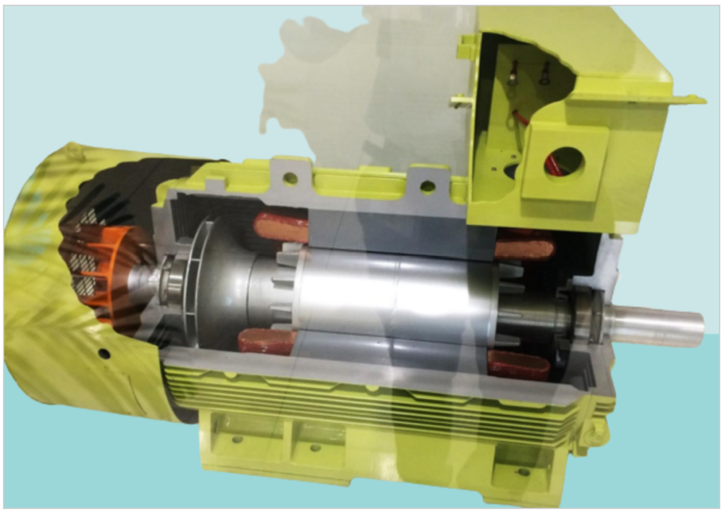
What’s inside an induction motor?

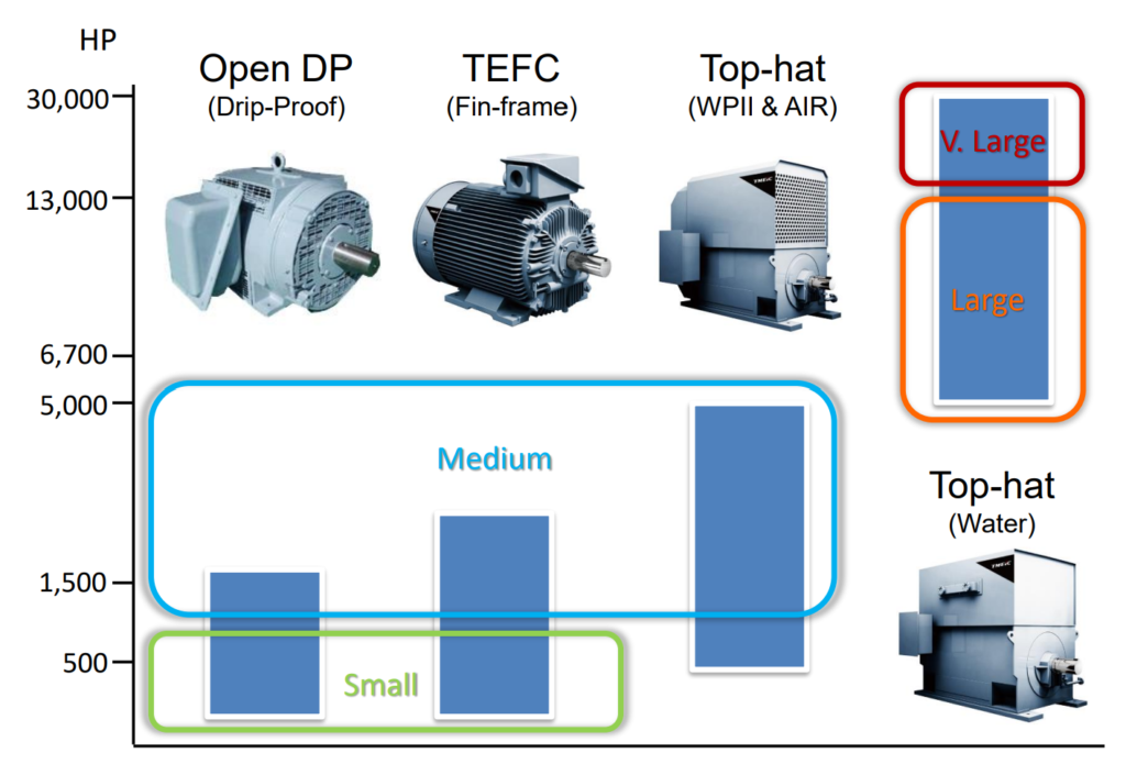
Sizes for MV Motors:
How Induction Machines are Built and Work?
Induction machines, commonly known as induction motors, are the most widely used type of electric motor due to their simplicity, reliability, and versatility. Here’s a brief overview of how induction motors are built and how they work:
Construction of Induction Motors:
- Stator: The stator is the stationary part of the motor and consists of a laminated core made of iron or steel sheets. Around the inner circumference of the stator, there are evenly spaced slots for winding coils. These coils are connected in a way that creates a rotating magnetic field when AC power is supplied.
- Rotor: The rotor is the rotating part of the motor and is placed inside the stator. There are two common types of rotors:
- Squirrel Cage Rotor: This is the most common type of rotor. It consists of laminated iron cores with conductive bars (usually made of aluminum or copper) embedded in them. These bars resemble a squirrel cage, hence the name.
- Wound Rotor: In this type, the rotor windings are wound around the rotor core and are externally connected to a set of slip rings. These slip rings allow for external electrical connections, providing additional control over the motor’s performance.
- Bearings: Induction motors have bearings that support the rotor and allow it to rotate within the stator. Proper bearing lubrication and maintenance are essential for motor longevity.
- Enclosure: The motor is typically housed in an enclosure to protect it from environmental factors such as dust, moisture, and physical damage. Various types of enclosures are used to suit different applications.
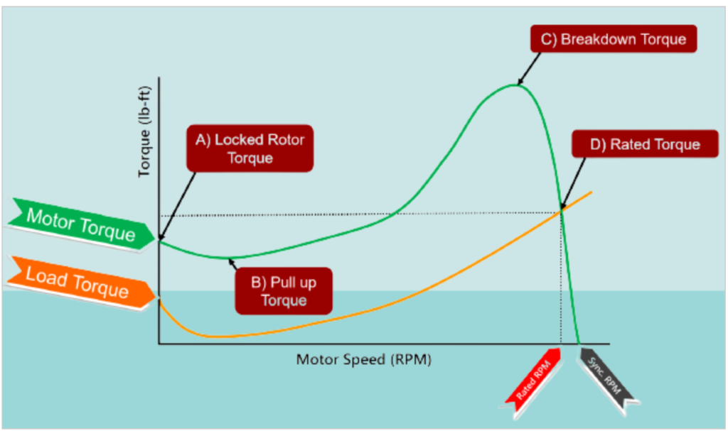
Induction motor speed vs. torque profile:
NEMA Standards & Applications
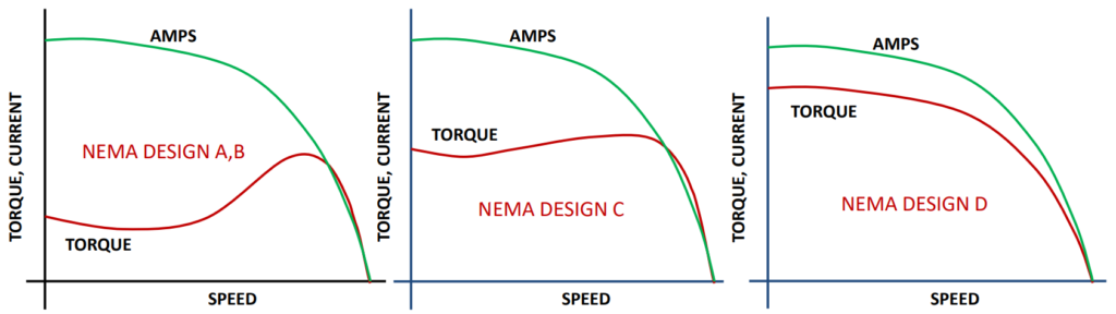
NEMA (National Electrical Manufacturers Association) motor designs are categorized based on their starting torque characteristics, which are suited for different types of applications. Here’s a breakdown of the NEMA motor designs and their typical applications:
- NEMA Design B (Standard Starting Torque):
- Applications: Fans, blowers, centrifugal pumps, and compressors.
- Torque Characteristics: Variable torque applications. These motors provide moderate starting torque suitable for applications where the load varies during operation.
- NEMA Design C (High Starting Torque):
- Applications: Reciprocating compressors, positive displacement pumps, screw compressors.
- Torque Characteristics: Constant torque applications. These motors offer a higher starting torque and are ideal for equipment that requires a consistent level of torque throughout operation.
- NEMA Design D (Highest Starting Torque, High Slip):
- Applications: Car shredders, punch presses, shears, elevators, winches, hoists, oil-well pumping.
- Torque Characteristics: These motors provide the highest starting torque and have high slip. They are designed for demanding applications that require a significant torque boost during startup or under heavy loads.
Motor starting characteristics & starting time:

Interaction between stator & Rotor:
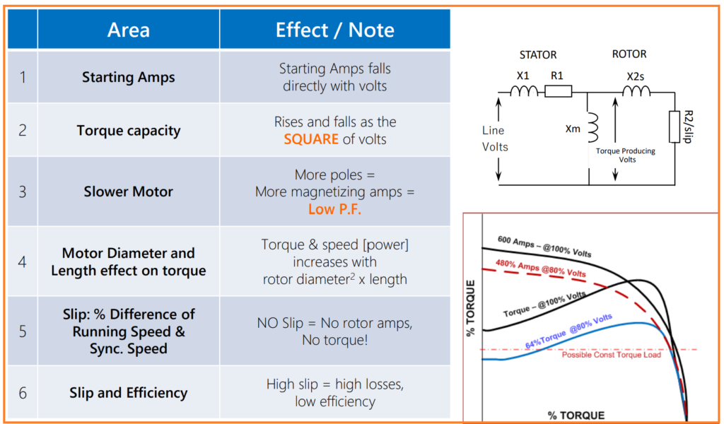
Summary of electrical relationships in MV Motors:
These are important notes and considerations related to the operation and characteristics of electric motors, particularly in relation to voltage, torque, motor size, and efficiency:
- Starting Amps: Starting current (starting amps) decreases as voltage increases. This is important to consider when selecting a motor for a specific voltage supply.
- Torque Capacity: The torque capacity of a motor is proportional to the square of the voltage. Increasing voltage significantly increases the available torque.
- Slower Motor: Motors with more poles tend to run at slower speeds and may require higher magnetizing amps, leading to a lower power factor (P.F.). The number of poles affects motor characteristics.
- Motor Diameter and Length: The size of the motor, specifically its diameter and length, can have a significant impact on torque and speed. Increasing rotor diameter squared by the length results in higher torque and power.
- Slip: Slip refers to the percentage difference between the running speed and synchronous speed of a motor. Zero slip indicates no rotor amps and no torque production.
- Slip and Efficiency: High slip in a motor results in increased losses and lower efficiency. Reducing slip is essential for improving motor efficiency.
These considerations are crucial when designing, selecting, and operating electric motors for various applications. Understanding how voltage, torque, motor size, and slip affect motor performance is essential for optimizing efficiency and ensuring motors meet specific operational requirements.
Motor Selection Process:
The process of selecting an electric motor for a specific application involves considering various electrical and mechanical specifications. Here are key requirements and specifications to consider when selecting a motor:
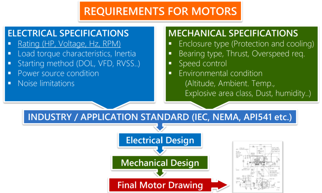
Electrical Specifications:
- Rating: Determine the motor’s power rating in terms of horsepower (HP), voltage, frequency (Hz), and speed in revolutions per minute (RPM). These parameters should match the application’s power requirements.
- Load Torque Characteristics: Understand the load torque characteristics of the application, including torque requirements at different operating conditions and any variations over time. Consider the load’s inertia as well.
- Starting Method: Decide on the motor’s starting method, whether it’s direct-on-line (DOL), variable frequency drive (VFD), or reduced voltage soft starter (RVSS). The starting method affects motor performance and protection.
- Power Source Condition: Ensure that the motor’s electrical requirements align with the available power source conditions, including voltage levels and frequency stability.
- Noise Limitations: Consider any noise limitations or requirements for the application, especially if noise reduction is critical.
Mechanical Specifications:
- Enclosure Type: Choose an appropriate motor enclosure type based on the environmental conditions and protection requirements. Enclosures provide cooling and protection against dust, moisture, and other factors.
- Bearing Type: Select the appropriate bearing type (e.g., ball bearings, roller bearings) based on the motor’s load, speed, and expected operational conditions.
- Thrust and Overspeed Requirements: Determine if the motor needs to handle thrust loads or operate at overspeed conditions. Some applications may have specific thrust or overspeed requirements.
- Speed Control: Consider whether speed control is necessary for the application. This could involve using variable frequency drives (VFDs) or other speed control methods.
- Environmental Conditions: Account for environmental factors such as altitude, ambient temperature, explosive area classification, dust levels, humidity, and other conditions that may affect motor performance and longevity.
By carefully evaluating these electrical and mechanical specifications in the motor selection process, you can ensure that the chosen motor is well-suited for the specific requirements of the application, leading to efficient and reliable operation.
Inertia in MV Motor:
When starting a motor from the utility frequency power source, several important considerations and challenges arise, particularly related to inrush current, rotor heating, and the number of starts allowed. Here are key points to keep in mind:

- Inrush Current: When a motor starts, it draws a significantly higher current than its normal operating current. This initial surge of current, known as inrush current, can be as high as 650% or more of the motor’s rated current. This can lead to voltage drops in the power supply and mechanical stresses on the motor’s windings and rotor.
- Limiting Starts: To protect the motor and the power supply, it’s common practice to limit the number of motor starts. For example, a common practice is to allow two consecutive cold starts (when the motor is at ambient temperature) followed by one hot start (when the motor has not completely cooled down). This practice helps extend the motor’s lifespan and prevents excessive wear and tear.
- Inertia Calculation: Motor design includes calculations to determine the maximum allowed inertia for the motor. Inertia refers to the motor’s resistance to changes in speed. Larger inertia requires a larger motor to handle the load effectively. It’s important to match the motor’s inertia capability with the requirements of the connected equipment.
- VFD (Variable Frequency Drive): When starting a motor using a VFD, there are typically no limits on the number of starts. VFDs allow for precise control of motor speed and acceleration, reducing the stress associated with frequent starts. Additionally, VFDs can limit the inrush current by gradually ramping up the motor’s speed.
Using a VFD offers more flexibility and control in motor starting and operation, making it a preferred choice in applications where frequent starts and variable speeds are required.
Overall, careful consideration of motor design, starting practices, and the use of technologies like VFDs can help mitigate the challenges associated with inrush current and frequent motor starts, ensuring reliable and efficient motor operation.
Insulation class & temperature rise:
The specifications for medium voltage (MV) motors typically include important information related to motor insulation and temperature rise. Here’s a concise explanation of these critical motor construction details:
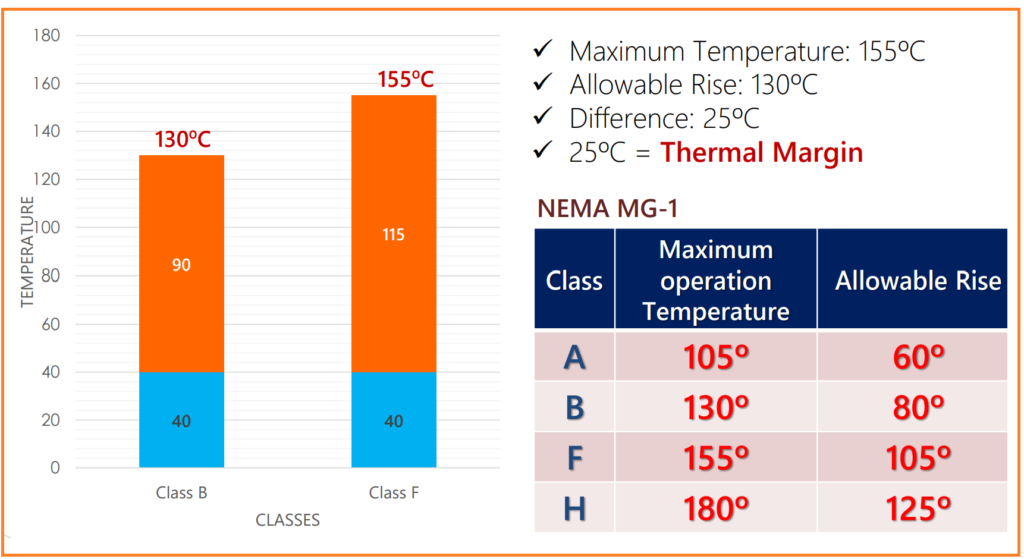
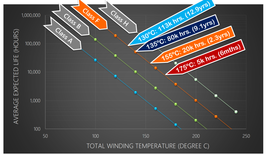
- Motor Insulation – Class F: This designation, “Class F,” refers to the insulation class of the motor. Class F insulation is a common standard in motor manufacturing. It indicates that the motor’s electrical insulation materials are designed to withstand higher operating temperatures. This ensures that the motor can operate safely even when subjected to elevated temperatures during normal operation.
- Motor Temperature Rise not to exceed Class B: This specification specifies that the temperature rise of the motor during operation should not exceed Class B limits. Class B temperature rise is an industry standard that defines the maximum allowable temperature increase of the motor’s windings and other critical components above the surrounding ambient temperature. Staying within Class B limits helps ensure that the motor remains within safe temperature ranges, preventing overheating and insulation breakdown.
In summary, the motor’s insulation class (Class F) and the requirement not to exceed Class B temperature rise are crucial aspects of motor construction and performance. These specifications guarantee the motor’s ability to handle higher temperatures and maintain safe operating conditions, promoting reliability and longevity in various applications.
Motor insulation
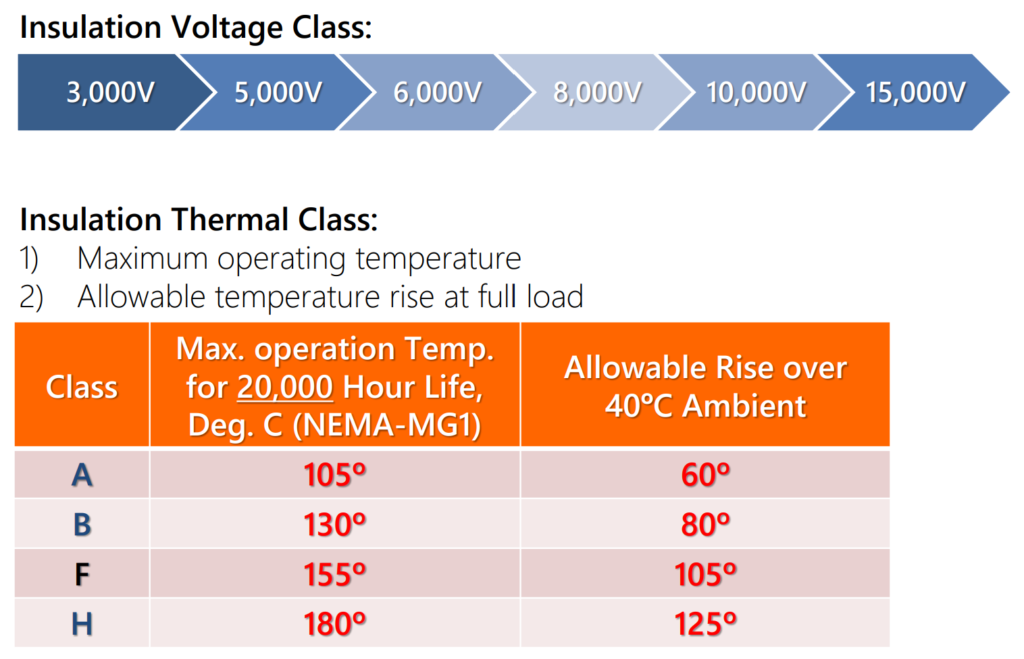
Insulation & Temp. Rise Class:
Insulation Average Expected Life Vs. Operating Temperature:
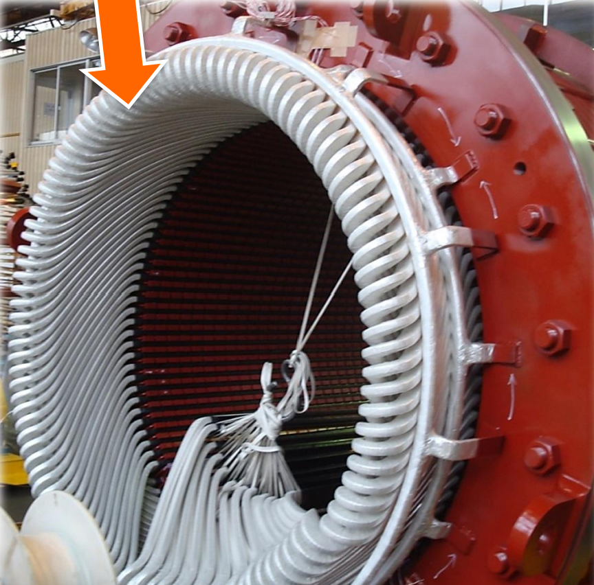
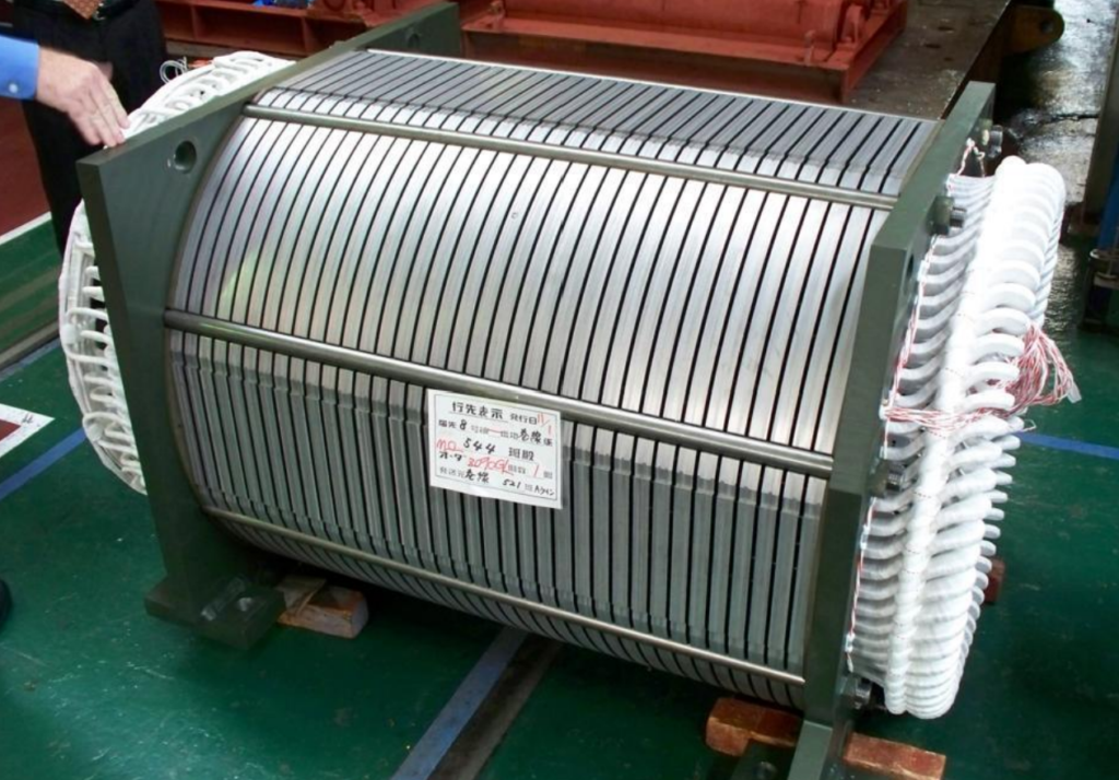
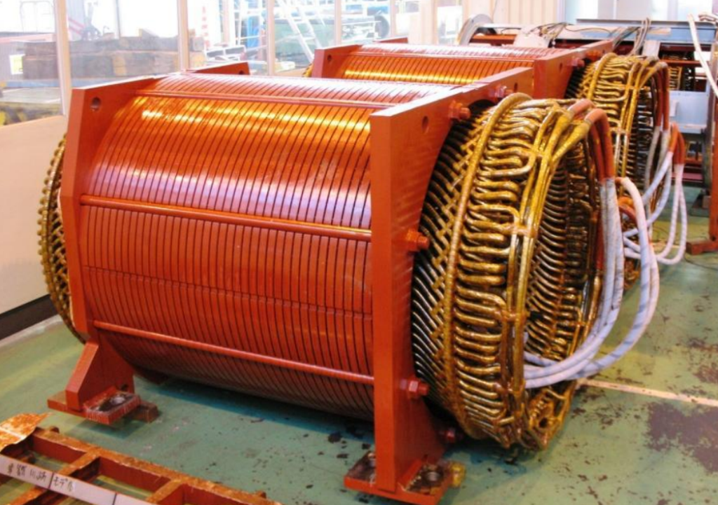
Form wound stator coil
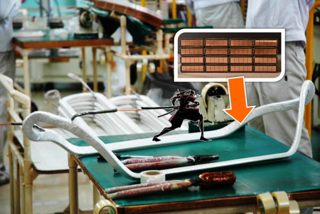
Stator core with form wound coils:
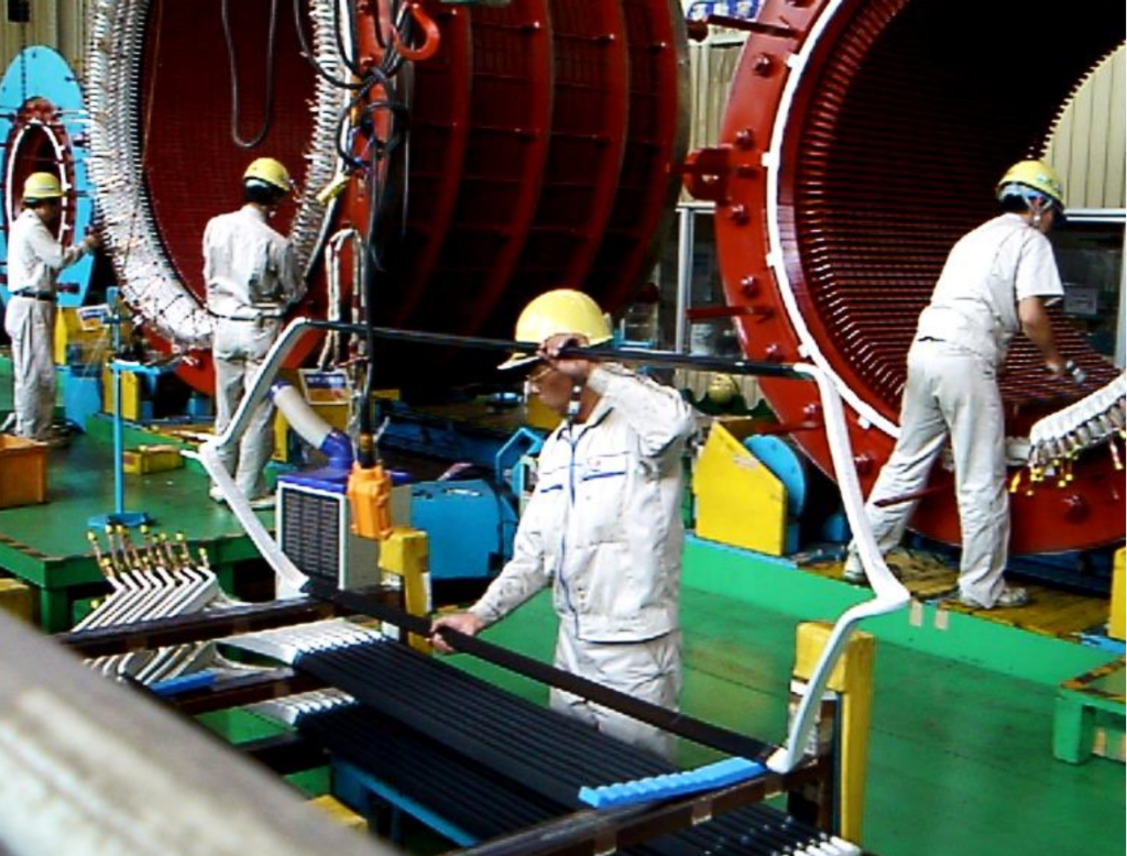
Winding Temperature detectors & bracing:
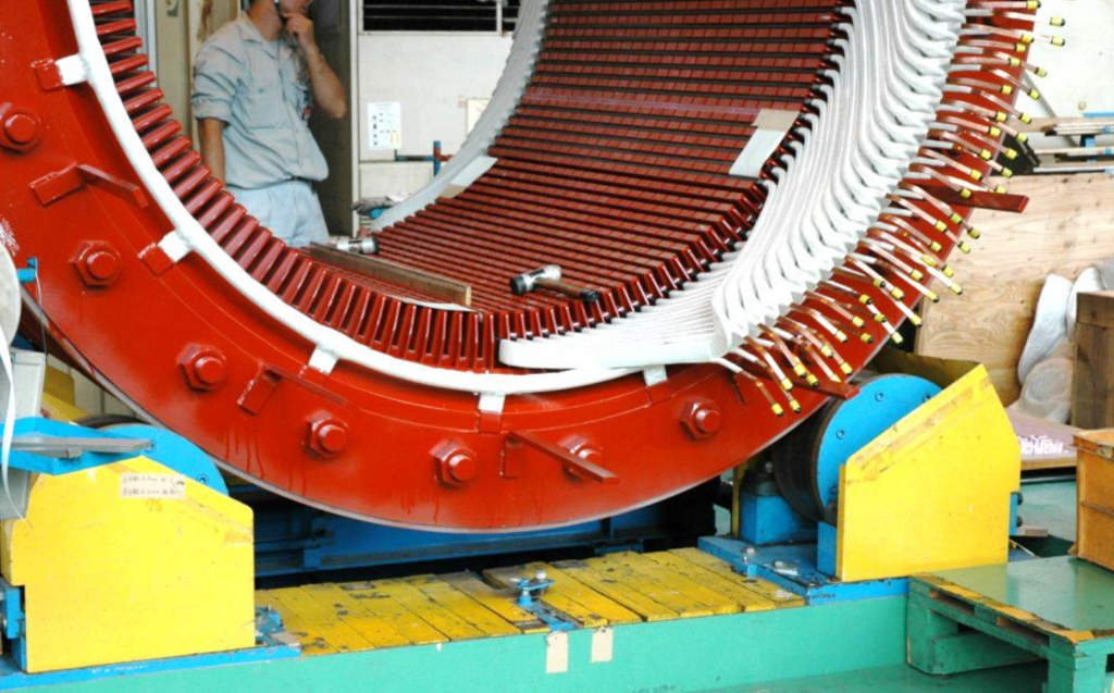
Stator core with windings in place:
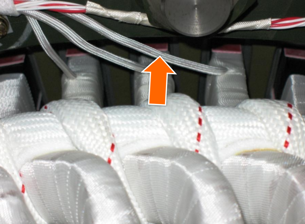
VPI (Vacuum pressure impregnation) Process in Medium Voltage Motor:
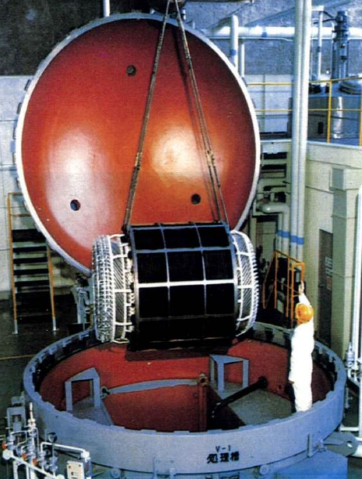
The VPI (Vacuum Pressure Impregnation) process is a critical step in the manufacturing of medium voltage (MV) motors, ensuring their electrical insulation system is robust and reliable.
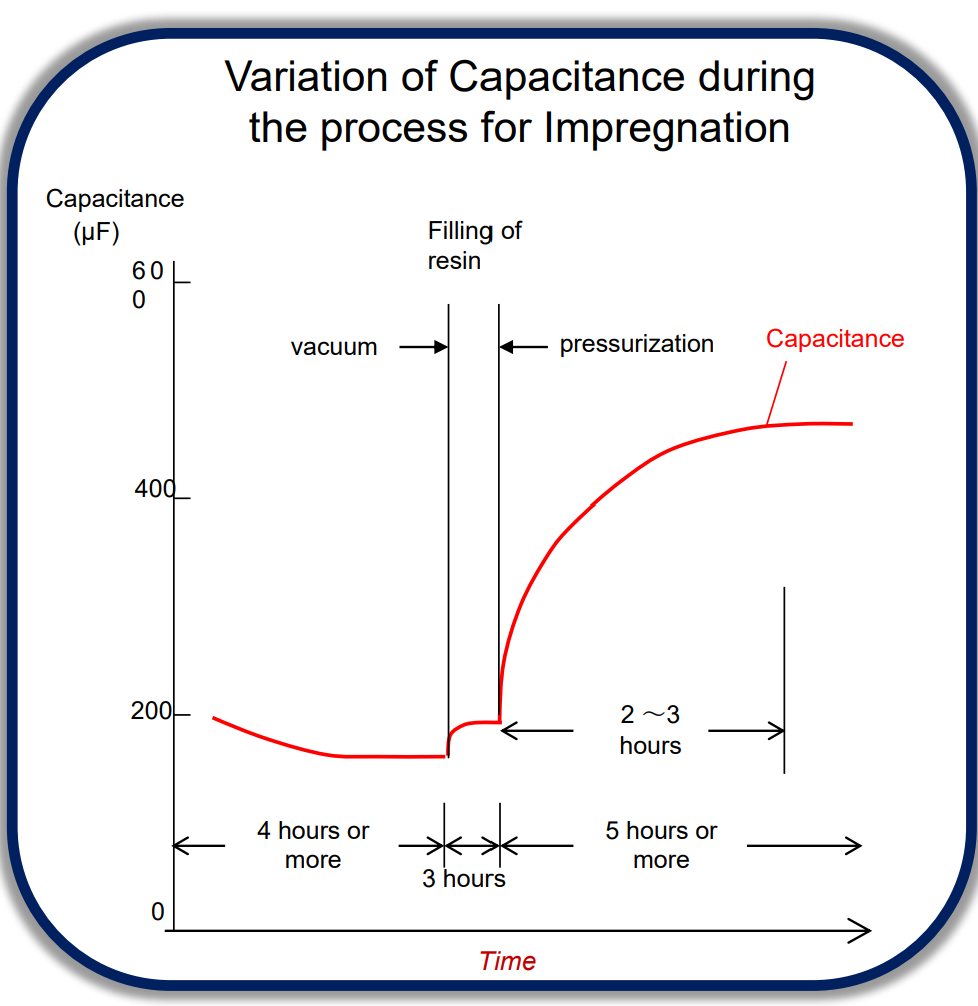
Moisture Removal: Vacuum is used to draw out moisture from the stator windings and assembly, creating a dry environment essential for effective impregnation.Resin Addition: Resin is introduced into the assembly at atmospheric pressure. This liquid resin serves as the insulating material that will protect the windings.Pressurization: The assembly is pressurized to force the resin into all voids and gaps within the windings. This step ensures complete impregnation and eliminates air pockets.Capacitance Measurement: Capacitance levels of the windings are monitored during the process. An increase in winding capacitance indicates that the impregnation process is complete, as the resin has filled all voids.
Stator core after VPI:
The winding is transformed into a solid mass, providing protection against operational and starting forces. Additionally, the VPI process effectively seals out moisture from the surrounding environment.
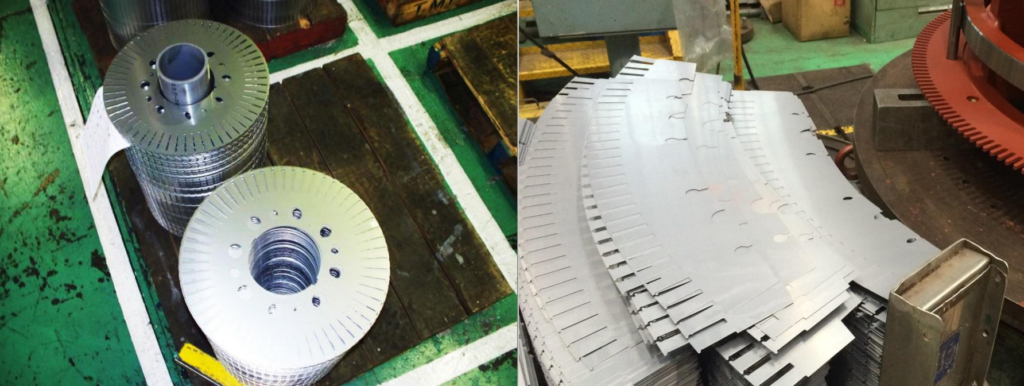
MV Motor Rotor laminations:
Rotor shaft & Air baffle:

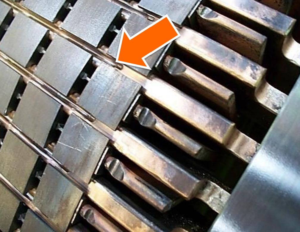
Copper bar insertion:
The copper bars are precisely trimmed and finished using a lathe. Subsequently, end rings will be brazed to the ends of these bars to complete the assembly.
MV Motor Assembled rotors:
Swaging of MV Motor
Swaging is the process in which copper bars are firmly inserted into slots within the motor assembly. This swaging process achieves several benefits, including a secure and tight fit for the bars. It also helps prevent sparking, reduces vibration, and minimizes noise during motor operation.
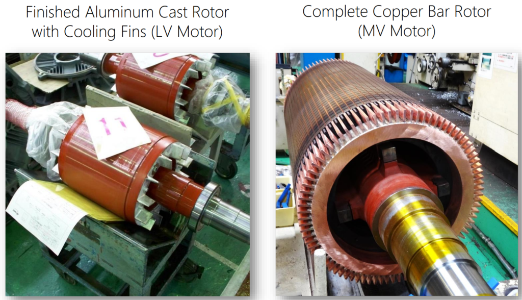
Completed Rotors
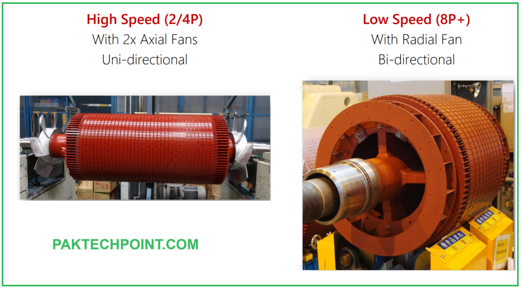
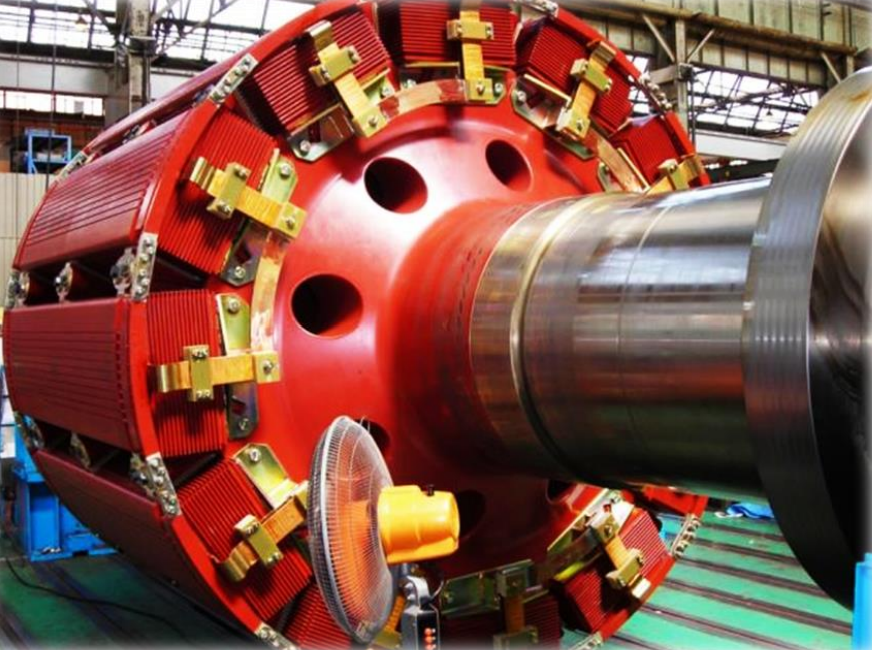
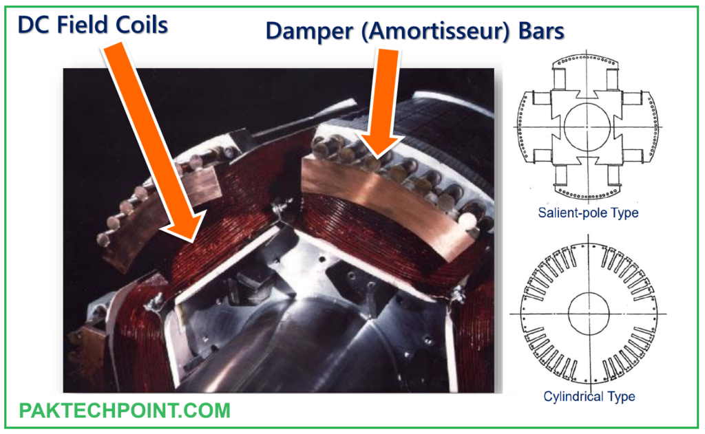
Rotor of a Synchronous motor:
The rotor of a synchronous motor features a complex design comprising two distinct flux circuits:
- DC Current Flux Circuit:
- This circuit consists of field poles that alternate between North and South magnetism. The polarity and strength of this magnetic field are externally controlled.
- The DC current flux circuit plays a crucial role in establishing the synchronous operation of the motor by creating a fixed magnetic field.
- Induction Flux Circuit:
- The induction flux circuit within the rotor is designed similarly to a squirrel cage induction motor.
- It includes “Damper Bars” or “Amortisseur Windings,” typically in the form of round bars, which serve the purpose of aiding motor starting.
- These damper bars contribute to the initial rotation of the rotor during startup, ensuring that the motor reaches synchronous speed and locks into the grid frequency.

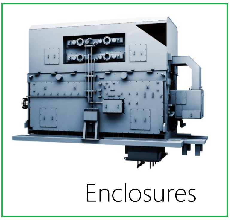
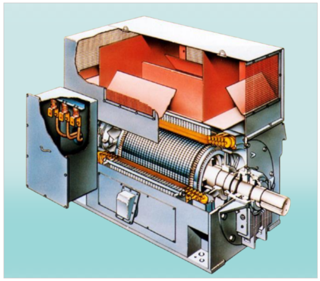
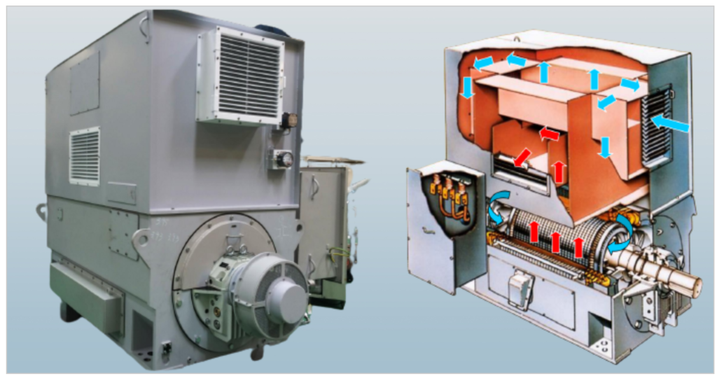
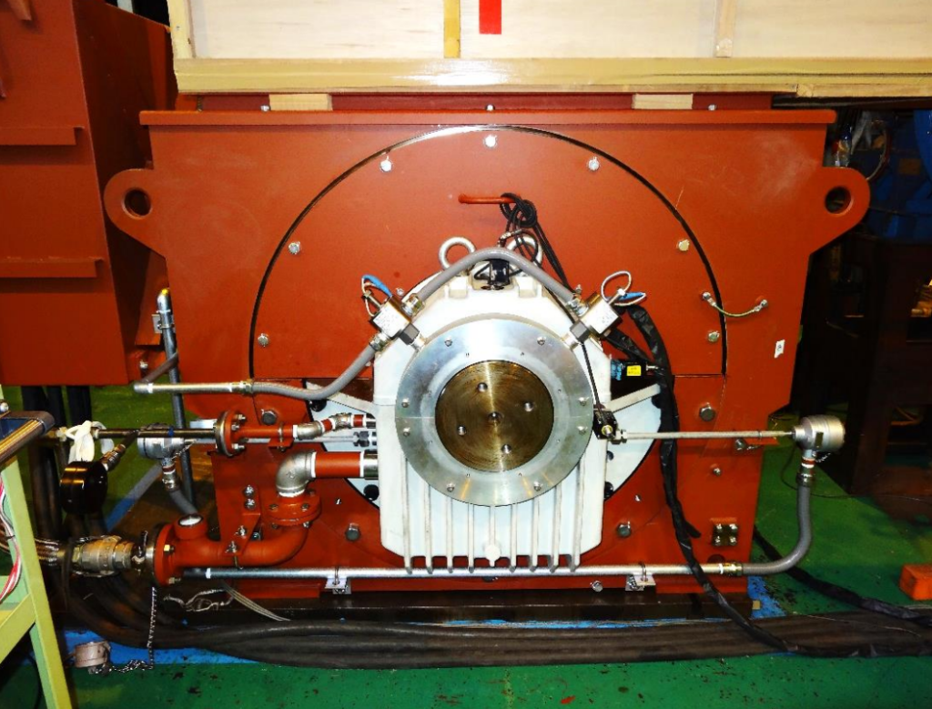
MV Motor enclosures:
Motor enclosures serve two essential functions in motor operation:
- Protection: Motor enclosures provide a protective barrier around the motor’s internal components. This protection safeguards the motor from environmental factors such as dust, moisture, contaminants, and physical damage. It helps ensure the motor’s reliable and safe operation by preventing external elements from affecting its performance.
- Heat Removal: Another crucial role of motor enclosures is heat removal. During motor operation, electrical and mechanical processes generate heat. Excessive heat can be detrimental to a motor’s efficiency and lifespan. The motor enclosure is designed to dissipate this heat efficiently, maintaining the motor’s temperature within safe limits. Heat removal is essential for preventing overheating and insulation breakdown.
Totally Enclosed Fan Cooled (TEFC)
The Totally Enclosed Fan Cooled (TEFC) motor enclosure type, often labeled as IP55 or IC411, offers several characteristics:
- Cost-Effective: TEFC enclosures are cost-effective and provide reliable protection for motors.
- Versatile Use: They are suitable for both indoor and outdoor applications, making them versatile choices for various environments.
- Limited Capacity: TEFC enclosures are not available for large-capacity motors. They are typically used for motors with a power rating of up to approximately 3000 horsepower (HP).
TEFC motors are a practical choice for many industrial and commercial applications where protection from environmental factors and efficient heat dissipation are essential.

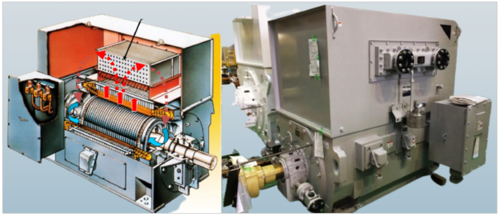
Weather-protected type II (WPII, IP24W, IC01)
The Weather-Protected Type II (WPII) motor enclosure, also known as IP24W or IC01, possesses the following characteristics:
- Outdoor Suitability: WPII enclosures are suitable for outdoor use, although they are less common outside of North America.
- Cost-Effective: They are generally considered cost-effective options.
- Effective Cooling: WPII enclosures provide effective cooling for the motor’s windings, contributing to reliable performance.
- Noise Generation: One drawback is that WPII motors can be noisy during operation.
These motors are well-suited for outdoor applications in North America, where their cost-effectiveness and cooling capabilities are advantageous, even though they may produce more noise compared to some other enclosure types.
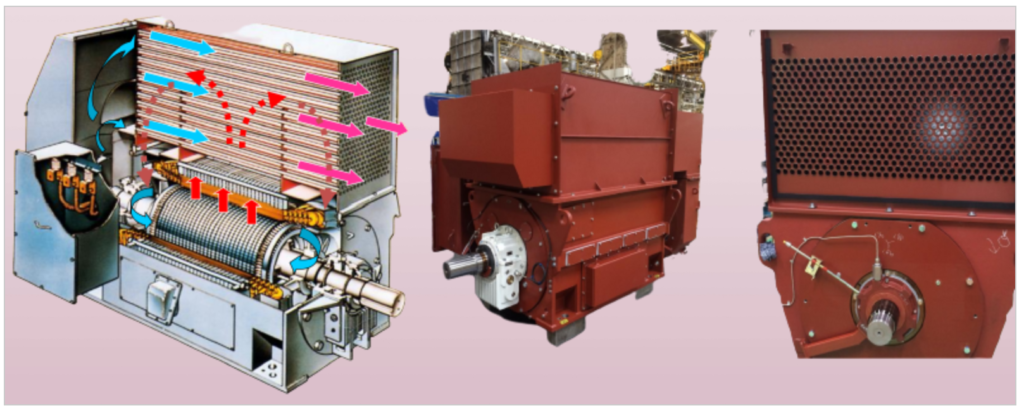
Totally enclosed air to air cooled (TEAAC, IP55, IC611):
The Totally Enclosed Air to Air Cooled (TEAAC) motor enclosure, often labeled as IP55 or IC611, exhibits the following characteristics:
- Outdoor Suitability: TEAAC enclosures are suitable for outdoor use and are more common outside of North America.
- Costly: They tend to be more expensive compared to some other enclosure types.
- Moderate Cooling: While they provide cooling through an air-to-air mechanism, it may not be as effective as some other cooling methods. Larger TEAAC motors are available but may not cool the windings as efficiently as smaller motors.
- Limited for Extremely Large Motors: TEAAC enclosures are not typically available for extremely large capacity motors.
Totally enclosed water to air cooled (TEWAC, IP55, IC81W):
The Totally Enclosed Water to Air Cooled (TEWAC) motor enclosure, often labeled as IP55 or IC81W, possesses the following characteristics:
- Outdoor Suitability: TEWAC enclosures are suitable for outdoor use, making them ideal for a variety of applications.
- Cooling Requirement: They require cooling water for effective operation. This cooling method ensures efficient heat dissipation.
- Costly: TEWAC motors tend to be relatively expensive due to their specialized cooling system.
- Efficient Cooling: They offer efficient cooling, similar to the winding cooling capabilities of WPII enclosures, even for motors of the same size.
- Available for Extremely Large Motors: TEWAC enclosures are available for extremely large capacity motors, making them suitable for heavy-duty applications.
- Quiet Operation: One advantage is that TEWAC motors operate quietly.
Motor frame size – IEC conventions

MV Motor Anti-friction bearings:
Anti-friction bearings, often referred to as rolling bearings or ball bearings, have several characteristics:
- Cost-Effective: They are generally less expensive compared to sleeve bearings.
- Thrust Load Capacity: Anti-friction bearings are suitable for applications with thrust loads, making them versatile for various machinery.
- Regular Lubricant Maintenance: They require relatively short lubricant changing intervals, typically in months. Proper lubrication is essential for their performance and lifespan.
- Speed Limitations: They are not usually suitable for very high-speed applications, especially in 2-pole motors.
- Limited Bearing Life: Anti-friction bearings have a limited bearing life, often measured by the L-10 life, with typical values ranging from 20,000 to 100,000 hours. This indicates that a certain percentage of bearings are expected to still be operational at the specified number of hours, and the rest may fail.
These bearings are commonly used in various industrial and mechanical systems due to their cost-effectiveness and suitability for thrust loads. However, they may not be ideal for extremely high-speed or long-duration applications.

Self-lube Sleeve bearings:
Self-lubricating sleeve bearings, also known as plain bearings or bushings, exhibit the following characteristics:
- Long Bearing Life: They offer a long bearing life, making them suitable for applications where extended durability is essential.
- Extended Lubrication Intervals: Lubricant changing intervals for self-lube sleeve bearings are typically long, ranging from 1 to 2 years, reducing maintenance requirements.
- Higher Cost: They are more expensive compared to anti-friction (A-F) bearings, which should be considered when selecting them for specific applications.
- Not for Thrust Loads: Self-lube sleeve bearings are not suitable for applications with thrust loads, limiting their use in certain machinery.
- Limited for Extreme Temperatures: They may not be suitable for extreme ambient temperature conditions, as the lubrication properties and performance of these bearings can be affected.
Self-lubricating sleeve bearings are commonly chosen for applications where bearing life and reduced maintenance are paramount, even though they may come at a higher cost compared to anti-friction bearings. However, their limitations regarding thrust loads and extreme temperatures should be taken into account when making a selection.
Force-lube Sleeve bearings:
Force-lubricated sleeve bearings possess the following characteristics:
- Long Bearing Life: They offer a long bearing life, making them suitable for applications where extended durability is essential.
- High-Speed and High-Load Capabilities: Force-lube sleeve bearings are designed to cover a high-speed and highly-loaded range, making them ideal for heavy-duty machinery.
- Continuous Lubrication: Unlike some other bearings, no shutdown is required for lubricant changing with force-lubricated sleeve bearings. They receive continuous lubrication during operation.
- Oil-Circulation System: To ensure proper lubrication, these bearings require an oil-circulation system that supplies lubricant to the bearing as needed.
Force-lubricated sleeve bearings are commonly used in demanding applications where bearing longevity and performance under high loads and speeds are essential. Their continuous lubrication feature ensures smooth operation without the need for shutdowns for lubricant changes. However, the presence of an oil-circulation system should be considered in the design and installation process.
Service Factor of MV Motor:
The Service Factor (S.F.) specified for Medium Voltage (MV) Motors, such as 1.15 S.F., indicates the motor’s ability to temporarily produce more power than its rated capacity. Here’s what it means in terms of motor size and design:
- Power Output: A nameplated 1,000HP motor with a 1.15 S.F. must be capable of producing 1,150HP when needed. This additional power output is for temporary surges or overloads.
- Temperature Consideration: While producing this extra power, the motor should not exceed its temperature specifications or the maximum allowable temperature for the operating environment. This ensures that the motor can handle the increased load without overheating.
- API Equipment Specs: In some cases, equipment specifications driven by organizations like API (American Petroleum Institute) may require an additional 10% above the HP (Horsepower) requirement. With a 15% Service Factor, the motor size effectively becomes 26% larger to accommodate these extra power demands.
It’s important to note that specifying a higher Service Factor adds cost and increases the size and weight of the motor. However, it provides a safety margin and flexibility for handling intermittent or short-term overloads, which can be critical in industrial applications where sudden power demands may occur.
Ambient temperature & Altitude of MV Motor
Ambient temperature and altitude have significant effects on the performance and design of motors, with considerations including:
- Ambient Temperature: NEMA and IEC motors are typically rated for operation at a 40°C (104°F) ambient temperature. Extreme temperatures below -20°C (-4°F) may necessitate a review of bearing lubrication. Below -40°C (-40°F), the material properties of the motor’s shaft steel and frame should be evaluated. Operating in temperatures below -50°C (-58°F) requires substantial changes to the motor’s design and construction. Conversely, in environments with temperatures exceeding +40°C (+104°F) or hotter, the motor may need to increase in size, along with considerations for bearing lubrication.
- Altitude: Altitude plays a role in motor performance as well. At altitudes above 1,000 meters (approximately 3,300 feet), the motor may require an increase in size or de-rating to account for lower air density and reduced cooling capacity.
Both ambient temperature and altitude are critical factors in determining the suitability and design of motors for specific operating conditions, and they should be carefully considered during motor selection and application.

VFD Duty Motor Design
Variable Frequency Drive (VFD) duty motors are designed with specific features and considerations to ensure reliable performance in VFD applications. Here are some key aspects of their design:
- Compliance with NEMA-MG1 Part 31: VFD duty motors are designed in accordance with the standards outlined in NEMA-MG1 Part 31, which provides guidelines for motor designs intended for use with variable frequency drives.
- Stiff Shaft for 2-Pole Machines: In 2-pole machines, having a stiff shaft is crucial to avoid critical speed issues, which can lead to excessive vibrations and potential motor damage.
- Insulation Reinforcement: These motors feature insulation systems that can withstand the surge voltages generated by VFDs, ensuring protection against electrical stress.
- Specialized Cooling Design: VFD duty motors are equipped with cooling systems optimized for torque load at lower speeds. Some applications may require an auxiliary blower for continuous cooling, even at lower speeds.
- Shaft Current Protection: To prevent bearing electric discharge erosion, shaft current protection measures are implemented. This typically involves insulating the non-drive end bearing and grounding the drive shaft end with a grounding brush. In hazardous areas, both bearings may be insulated, and an insulated coupling may be used for added protection.
VFD duty motors are engineered to handle the unique challenges posed by variable frequency drive applications, ensuring their durability and reliability in industrial settings where VFDs are commonly used.

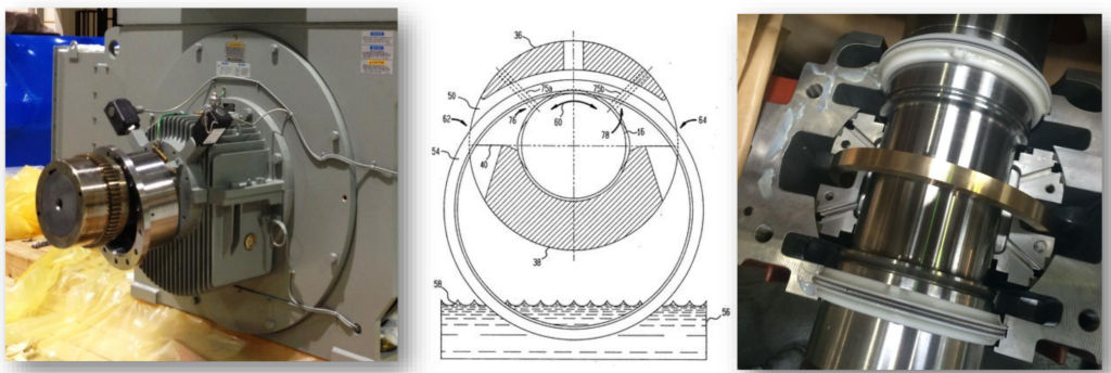
Shaft current protection in MV Motor
Shaft current protection measures for motors can vary depending on the specific application and environmental conditions. Here are some common shaft current protection options:
Standard Shaft Current Protection:
- Non-Drive End (NDE) Bearing Insulated: The non-drive end bearing is typically insulated to prevent shaft current from damaging the bearing.
VFD Duty Standard Shaft Current Protection:
- NDE Bearing Insulated: Similar to the standard protection, the non-drive end bearing is insulated.
- Grounding Brush: A grounding brush is added to the drive shaft end to provide an additional grounding path and help dissipate any shaft currents.
Hazardous Locations Shaft Current Protection:
- Both Bearings Insulated: In hazardous locations or more critical applications, both the drive end and non-drive end bearings may be insulated for enhanced protection.
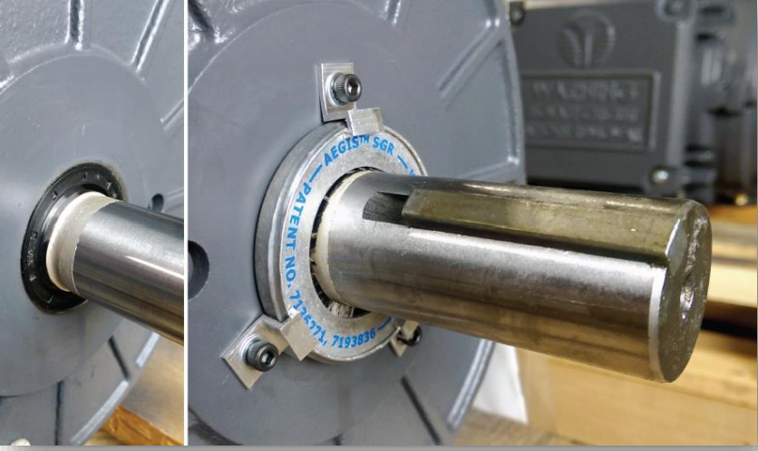
Optional Shaft Current Protection Components:
- Aegis Ring: An Aegis Ring is an additional grounding device designed to divert shaft currents away from the bearings.
- Insulated Couplings: Insulated couplings are used to electrically isolate the motor’s shaft from the driven equipment, preventing the flow of shaft currents.
- Ceramic Ball Bearings: Ceramic ball bearings can be used as an alternative to traditional steel ball bearings, as they are less susceptible to damage from shaft currents.
Terminal box types:
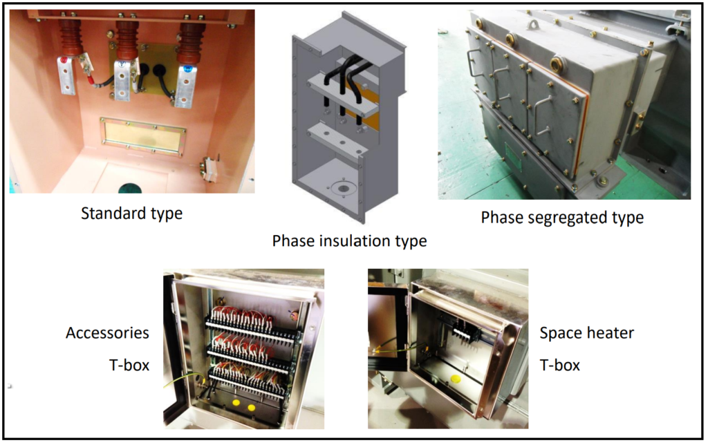
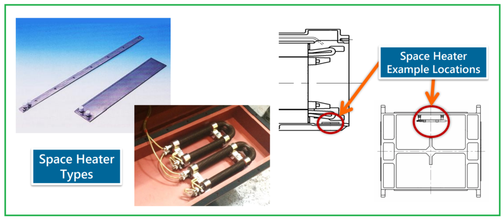
Space Heater:
A space heater in the context of motors is a device used to provide gentle and controlled heating to the motor’s internal components, particularly the winding insulation, in order to prevent moisture condensation (dew) and maintain the insulation’s integrity. Here are some key points about space heaters for motors:
- Moisture Prevention: Motors are often stored or installed in environments where temperature fluctuations can lead to the formation of condensation inside the motor frame. This moisture can be detrimental to the motor’s insulation and overall performance. A space heater helps maintain a stable and slightly elevated temperature within the motor, preventing the formation of moisture.
- Insulation Protection: The winding insulation of a motor is crucial for its safe and reliable operation. Exposure to moisture can lead to insulation breakdown and electrical faults. By using a space heater, the insulation is kept dry and free from moisture-related damage.
- Hazardous Areas: In hazardous areas where there may be flammable gases or dust, it’s essential to use space heaters with low surface temperatures to prevent ignition sources. These specialized heaters are designed to meet safety requirements and minimize the risk of sparking.
- Controlled Heating: Space heaters are designed to provide controlled and uniform heating. They are often equipped with thermostats or temperature sensors to maintain the desired temperature range inside the motor.
- Storage and Standby: Space heaters are commonly used when motors are in storage or on standby, ensuring that the motor is ready for operation when needed.
Temperature sensors

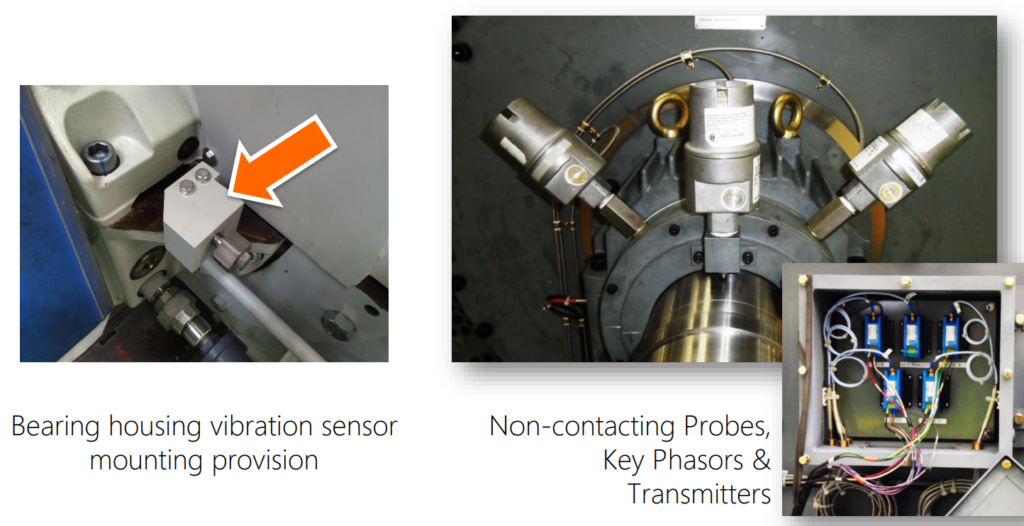
Vibration sensors
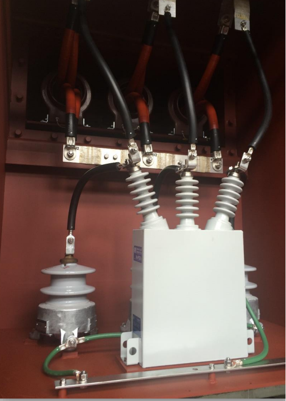
Surge protection for MV Motor
Surge protection devices, such as surge capacitors and surge arresters, are important components used in motor applications to safeguard the motor and associated equipment from voltage surges and transient voltage spikes.
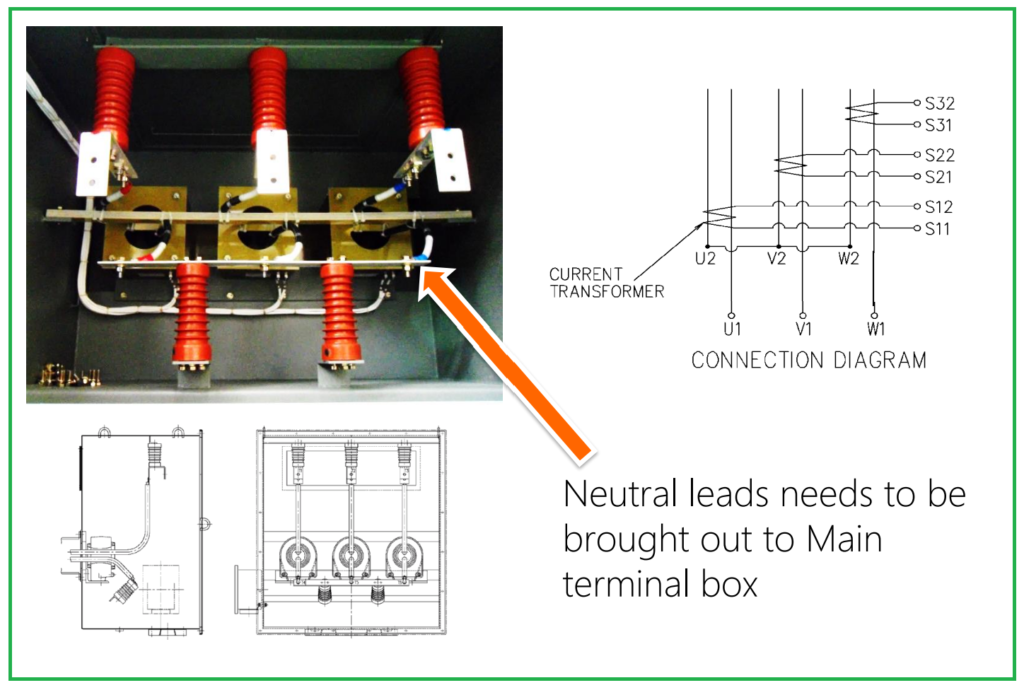
Current transformer in MV Motor
API541 – American Petroleum Institute Standard:
API541 is a significant standard developed by the American Petroleum Institute (API) for electric motors commonly used in the oil and gas industry. It outlines several essential requirements and criteria to ensure the reliability and performance of these motors in demanding industrial environments. Here’s a summary of key points from API541:
- Locked Rotor Current Limitation: The standard places a maximum limit of 650% on the locked rotor current. This limitation helps prevent excessive electrical stress during motor startup.
- Noise Limitation: API541 specifies a maximum noise level of 85 dB(A) for motors, ensuring that the motors operate at acceptable noise levels within industrial settings.
- Bearing Type: Sleeve bearings are commonly used in motors compliant with API541. Sleeve bearings offer specific advantages and are suitable for various operating conditions.
- Vibration Limits: The standard imposes strict limits on vibration levels, ensuring that motors meet specific performance criteria and minimize mechanical stress.
- Starting Requirements: Motors compliant with API541 must adhere to stringent starting requirements, including cold and hot starting procedures. This ensures that the motors can reliably start under various conditions.
- Quality Standards: API541 specifies minimum quality standards for critical motor components, such as the stator lamination core plates. This ensures the use of high-quality materials and manufacturing processes.
- Feet Coplanarity: The standard mandates that the motor’s mounting feet be coplanar within tight tolerances, ensuring proper alignment and secure installation.
- Routine Tests and Inspections: API541 requires the performance of 13 routine tests and inspections to verify motor quality and compliance with the standard’s requirements.
- Additional Test Items: The standard includes various test items and criteria to ensure the motor’s integrity, reliability, and performance in oil and gas applications.
API541 plays a crucial role in maintaining the safety and reliability of electric motors used in the oil and gas industry, where motors are exposed to harsh conditions and demanding operational requirements. Compliance with this standard helps ensure that motors can withstand the challenges of these environments and perform effectively over their operational lifespan.
Medium Voltage Motors Manufacturers:
Following is the list of Medium Voltage Motors Manufacturers.
- Eaton
- ABB
- Siemens
- Baldor
- Toshiba
- WEG
- Yaskawa
- GE
- Hyndai
Thanks for Reading!