The history of lead-acid battery development is a long and storied one, dating back to its invention in 1859 by a Frenchman named Plante. Over the course of more than a century, lead-acid batteries have undergone significant advancements and improvements. Here is a brief overview of the key milestones in their development:
- Invention of the Lead-Acid Battery (1859): Caston Plante invented the lead-acid battery, using two lead electrodes separated by a rubber roll soaked in a sulfuric acid solution. This early version showed promise in terms of repeated charging and discharging.
- Introduction of Pasted Plates (1881): Camille Faure introduced pasted plates to improve the performance of lead-acid batteries. However, these plates had issues with lead paste falling off.
- Grid-Shaped Grid Design (1881): To address the problem of lead paste falling off, the grid-shaped grid design was introduced. This design helped maintain the active substance on the plates.
- Triangular Cross-Section Grid (1889): Further improvements were made to the grid design, changing it to a triangular cross-section bar. This design increased the contact area between the lead paste and the grid, enhancing battery performance and lifespan.
- Advancements in the Early 1900s: By the early 1900s, lead-acid batteries had undergone significant improvements in terms of energy density, cycle life, and high-rate discharge performance.
- Challenges with Open Lead-Acid Batteries: Open lead-acid batteries had two major drawbacks: the need to add water and acid during charging and the risk of gas overflow, leading to environmental pollution.
- Development of Sealed Lead-Acid Batteries (1957): West Sunshine Company introduced gel-sealed lead-acid batteries, marking the birth of practical sealed lead-acid batteries.
- Lead-Calcium Alloy (1960s): The United States’ Gates Company invented the lead-calcium alloy, which further improved sealed lead-acid batteries’ development.
- Use in Space Exploration (1969): Sealed lead-acid batteries were used in the U.S. moon program to power lunar vehicles, contributing to their development.
- Introduction of Valve-Regulated Lead-Acid (VRLA) Batteries (1970s): The development of VRLA batteries began, aiming to address the challenges of open lead-acid batteries.
- Mass Production of VRLA Batteries (1979): GNB Company achieved mass production of large-capacity suction-sealed maintenance-free lead-acid batteries, advancing the technology.
- Telecommunications Sector Adoption (1980s): VRLA batteries gained popularity in the telecommunications sector due to their reliability and maintenance-free nature.
- Capacity Monitoring and Thermal Runaway (1990s): Challenges and doubts about VRLA batteries arose, leading to discussions and advancements in capacity monitoring and thermal runaway prevention.
- Global Adoption (2000s): VRLA batteries became widely used in various applications worldwide, including electric bicycles, scooters, telecommunications, and renewable energy.
- Lead-Acid Batteries in New Energy (2010s): Lead-acid batteries saw increased use in smart grids, solar and wind power plants, electric vehicles, and other fields, contributing to the development of new energy solutions.
Throughout its history, the lead-acid battery has evolved from its early iterations to become a reliable and widely used energy storage solution in various industries and applications.
Lead Acid Batteries Market and the usage:
Lead-acid batteries have maintained a significant presence in the market despite their lower energy density compared to other battery technologies such as Ni-Cd, Ni-MH, Li-ion, and PLIB. Their widespread usage can be attributed to several advantages, making them a preferred choice for various applications:
- Price Advantage: Lead-acid batteries offer a cost-effective energy storage solution. Their affordability makes them highly competitive in the market, especially for applications where cost is a significant consideration.
- Performance Advantages: Lead-acid batteries excel in certain areas, such as large current discharge performance. This characteristic is essential for applications requiring high-power output.
- No Memory Effect: Lead-acid batteries do not suffer from the memory effect, a phenomenon that can reduce the capacity of other battery types over time with repeated partial discharges.
- High Capacity Options: Lead-acid batteries can be manufactured in large capacities, making them suitable for applications requiring substantial energy storage, such as submarine batteries.
Market Insights and Usage Statistics:
- 1998: In 1998, the global chemical power output reached 264 million units, with primary batteries contributing $9.2 billion and secondary batteries (rechargeable) contributing $17.2 billion. Lead-acid batteries represented a substantial portion of secondary battery sales, accounting for $12.4 billion.
- Battery Council International (BCI) Survey (2000): According to a survey by BCI, the annual industrial growth rate of lead-acid batteries in 2000 was 8%, with global sales totaling $1.1 billion.
- Growth Expectations (2004): It was projected that lead-acid battery sales would continue to grow at a rate of 7% annually, with global sales reaching $1.5 billion by 2004.
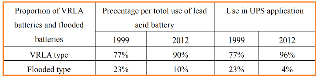
Despite initial challenges and doubts, especially related to issues like leakage, capacity loss, and battery life, VRLA batteries (Valve-Regulated Lead-Acid) made significant advancements in design technology. As a result, VRLA batteries gained a dominant position in various application areas of lead-acid batteries. This dominance is particularly evident in the field of Uninterruptible Power Supplies (UPS).
VRLA Battery Definition & Basic Characteristics
A Valve Regulated Lead-Acid Battery (VRLA battery) is a type of lead-acid battery characterized by its sealed, maintenance-free design. It does not require the addition of acid or water during its service life. Here are the basic characteristics of a VRLA battery:
- Sealed Structure: VRLA batteries are constructed with a sealed design, which means they do not have caps or openings for adding water or acid. This sealed structure prevents the escape of electrolyte and eliminates the need for periodic maintenance.
- Maintenance-Free: One of the key features of VRLA batteries is their maintenance-free operation. Unlike traditional flooded lead-acid batteries that require regular water top-ups to replenish the lost electrolyte, VRLA batteries are sealed and do not require any maintenance in this regard.
- No Acid Leakage: VRLA batteries are designed to be leak-proof. They do not release acid or electrolyte, making them safer to handle and suitable for use in various applications, including indoor and enclosed spaces.
- One-Way Exhaust Valve: VRLA batteries are equipped with a one-way exhaust valve, often referred to as a safety valve. This valve is designed to release excess gas generated during battery operation. When the internal gas pressure reaches a predetermined level, the valve automatically opens to release the gas. Once the pressure decreases, the valve closes to prevent air from entering the battery.
- Recombination of Gases: VRLA batteries are designed to recombine the gases generated during charging. This means that when gases like hydrogen and oxygen are produced within the battery due to overcharging or other factors, they combine to form water vapor, which is then retained within the battery rather than being released into the environment.
- Low Self-Discharge: VRLA batteries typically have a lower self-discharge rate compared to some other battery types. This characteristic allows them to hold their charge for extended periods without significant capacity loss.
- Usage in Various Applications: VRLA batteries find applications in a wide range of industries and applications, including uninterruptible power supplies (UPS), telecommunications, emergency lighting, security systems, renewable energy storage, electric mobility, and more.
VRLA batteries are maintenance-free, sealed lead-acid batteries with a one-way exhaust valve to release excess gas and prevent leakage of acid or electrolyte. Their design features make them suitable for diverse applications where safety, reliability, and low maintenance are essential considerations.
VRLA Classification and Advanced Technology Research
VRLA batteries come in two main types: AGM and GEL. AGM batteries use glass mats to absorb and hold the electrolyte, while GEL batteries use a gel-like electrolyte. AGM batteries can be installed vertically or horizontally, while GEL batteries are usually installed vertically. AGM batteries are versatile and commonly used, while GEL batteries are chosen for applications needing vibration resistance and deep cycling capability. VRLA batteries vary in size, from large with a 10-year design life to small with a 1-3 year design life.
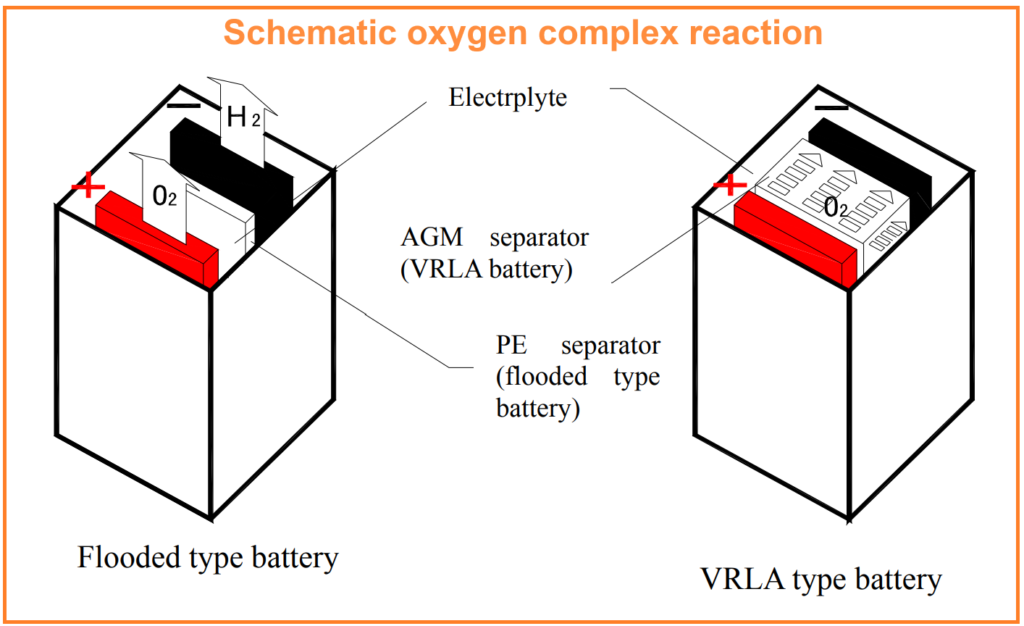
AGMT Technology
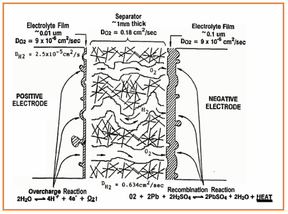
AGM (Absorbent Glass Mat) technology employs ultra-fine glass wool separators with a porosity of over 93% to absorb and hold sufficient electrolyte from reactions without allowing electrolyte flow inside the battery. This separator design maintains 10% of the pores as channels for oxygen (O2) to facilitate the oxygen cycle. O2 is generated at the positive electrode and then reacts at the negative electrode to complete the cycle: H2O → 1/2O2 → H2O, achieving a sealing effect.
AGM batteries are known for their advantages, including:
- Slow self-discharge rate (<2.0%) for extended storage periods at 25°C.
- Efficient charging.
- Low resistance (typically 0.2-0.9mΩ), for high-current discharge.
- High gas recombination efficiency (>98%), preventing mist formation.
- Higher initial cycle capacity, exceeding 100% of the rated capacity from the third cycle.
- Good discharge performance in low-temperature conditions.
These advantages have led to rapid development and widespread use of AGM VRLA battery technology in both domestic and international markets.
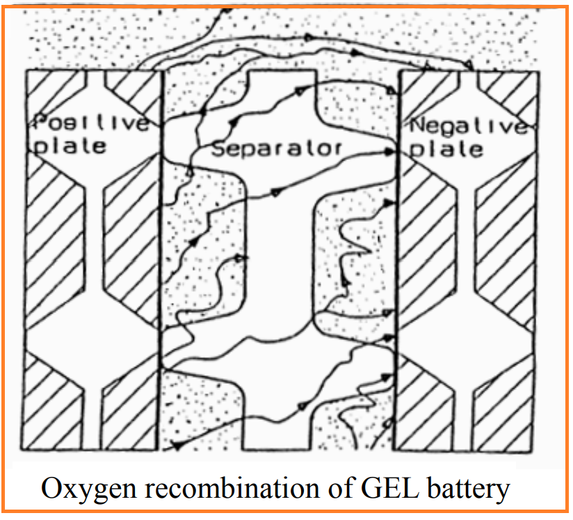
Gel technology
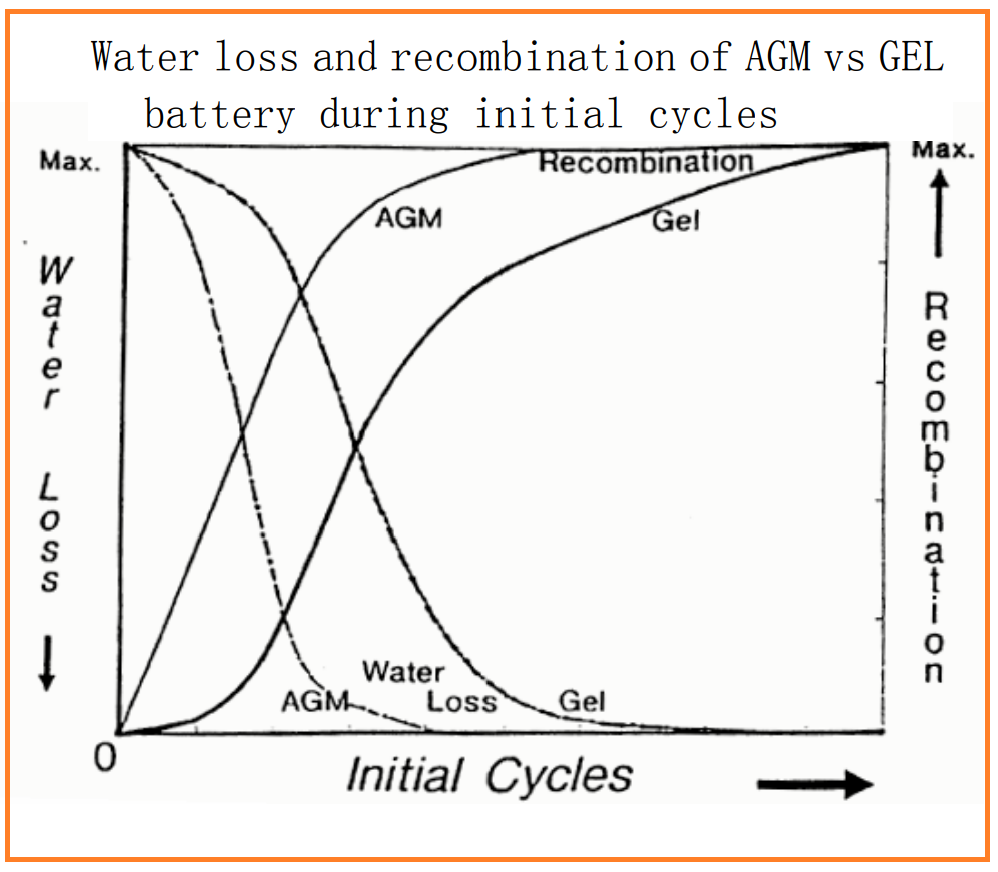
Gel technology, similar to AGM (Absorbent Glass Mat), relies on an oxygen cycle for its sealing mechanism. However, in gel batteries, oxygen from the positive cathode does not pass through the separator to reach the negative electrode pores. Instead, it is achieved through cracks in the colloid. These cracks act as channels for oxygen recombination within the colloid. Initially, gel batteries may have fewer cracks in the colloid, resulting in lower oxygen recombination efficiency and potentially causing the valve to open more frequently, leading to more mist precipitation. However, over time, the number of cracks increases, improving oxygen recombination efficiency.
Major manufacturers of gel batteries include Sonnenschein (Germany), Grompton Parkinson Company (USA), and FIAMM Company (Italy).
The preparation of gel electrolyte can be done through three methods: “Neutralization method,” “Silicon Sol method,” and “dioxide silicon method.” Among these, the “Silicon Sol method” is commonly used in many foreign countries, offering better stability for gel electrolytes.
Advantages of Gel technology:
- Gel batteries use a rich liquid design, making them capable of deep discharge recovery and better resistance to electrolyte dryness.
- Gel batteries exhibit minimal electrolyte stratification due to the use of colloids.
- Gel batteries have a longer lifespan than AGM batteries in higher ambient temperatures.
However, gel technology has some disadvantages:
a) During the initial usage period, the oxygen recombination efficiency is low, leading to more mist discharge.
b) Gel batteries are more sensitive to overcharging, and if the battery is tilted or lying down, the gel inside may flow out.
c) Gel batteries are not suitable for fast charging and high-rate discharge, especially at low temperatures.
d) Gel technology is not suitable for thin plate designs.
Overall, AGM batteries tend to be more efficient in terms of gas recombination compared to gel batteries. Gel batteries also have a higher water loss rate than AGM batteries.
In recent years, there has been increasing emphasis on gel technology in international conferences on lead-acid batteries. However, opinions on the advantages and disadvantages of AGM and Gel technology applications vary. Some believe that AGM technology is suitable for power-type batteries like electric vehicle and traction batteries due to their high current discharge performance. On the other hand, Gel technology is considered more suitable for backup batteries and UPS batteries. The choice between AGM and Gel technology depends on specific application requirements.
Advanced Research in VRLA Batteries Technology
Advanced research in VRLA battery technology has seen significant developments aimed at improving specific energy and deep cycle life. These innovations involve optimizing active material utilization and exploring new cell structures to reduce weight and enhance battery performance.
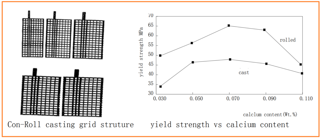
- Continuous Casting Roll Plate Grid Structure (Con-Roll Plate):
- Developed by East Penn and Wirtz.
- Addresses the issue of grid expansion and elongation during battery operation.
- Con-Roll Plate uses Pb-Ca alloy grids and continuous rolling during casting to increase yield strength (YS) and reduce ultimate tensile strength (UTS). This minimizes grid expansion and elongation during battery use.
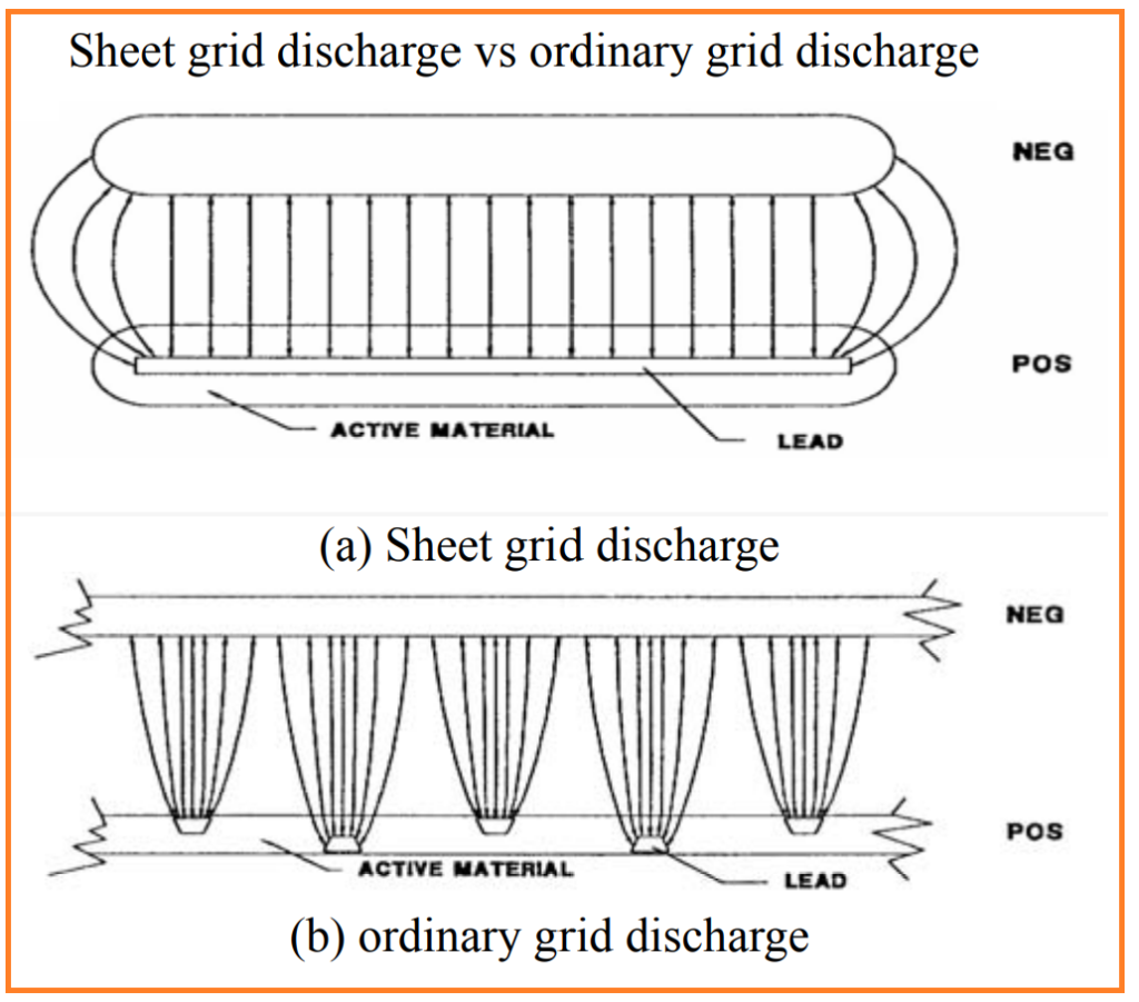
- Sheet Electrodes:
- Sheet grid positive poles offer more uniform charge and discharge performance compared to conventional cast or grid netting.
- Sheet grids with a high surface area exhibit reduced corrosion rates and lower corrosion current density (Acm-2) than normal grids. This technology is used in projects like East Penn’s ALABC.
- Foil Rolls Electrode (Thin Metal Film – TMF Technology):
- Electrodes as thin as paper, developed by U.S. BOLDER.
- Foil electrodes have a high specific power and excellent rechargeable performance.
- Grid thickness is only 0.05mm-0.08mm, which is similar to the thickness of the active material layer.
- Foil electrodes are well-suited for high-rate discharge applications and have been used in power tools, automotive starter batteries, and hybrid electric vehicles.
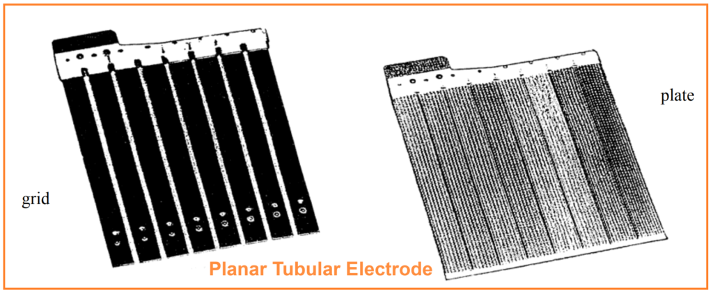
- Planar Tubular Electrode:
- Developed through the ALABC project by Yuasa.
- Grids are produced by casting or extrusion, using Pb-Ca-Sn alloy.
- The structure reduces the resistance between positive and negative electrodes, improving active material utilization and charge-discharge performance.
- Horizon Battery:
- Developed by D.B. Edwards at the University of Idaho for EV and HEV applications.
- Utilizes bipolar ear plates placed horizontally and a porous AGM separator.
- Features positive electrodes with glass bead additives.
- Horizon batteries offer high specific power and energy density, making them suitable for electric vehicles with extended range and high-speed capabilities.
Lead Fabric Batteries:
- Developed by Electrosource in the USA, these batteries use glass fiber filaments extruded with a Pb-Sn content.
- Lead cloth replaces traditional grids and helps reduce internal resistance.
- Lead fabric batteries exhibit high specific power, fast charging capabilities, and reduced weight.
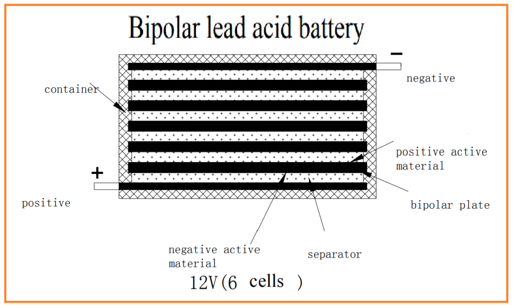
- Sealed Bipolar Lead-Acid Batteries (SBLA):
- SBLA batteries employ a bipolar plate structure, with double-sided plates separated by glass wool.
- The bipolar design reduces internal resistance and offers advantages such as high specific energy, long deep cycle life, and a simple structure.
- These batteries are suitable for applications requiring high voltage outputs.
Spiral Tubular Cylindrical Electrodes Battery:
- Introduced by U.S. EXIDE as the Orbital Select battery.
- Features spiral coil-shaped electrodes with a large surface area.
- Mechanically extrudes active substance into thin sheets.
- Utilizes continuous manufacturing technology to achieve a high compression ratio and reduce electrode thickness.
- Offers higher energy density and extended cycle life, making it suitable for garden car starter cartridges.
These advanced research efforts aim to enhance VRLA battery technology and make them more efficient, longer-lasting, and suitable for a wide range of applications, from electric vehicles to backup power systems.
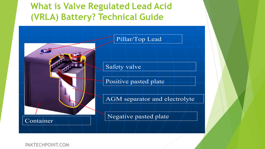
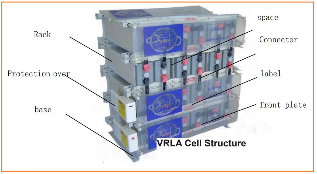
VRLA Basic Cell Structure:
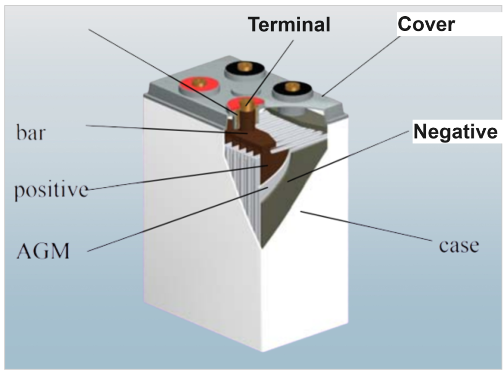
The basic structure of VRLA (Valve Regulated Lead-Acid) batteries consists of several key components, including:
- Positive Electrode (Cathode): The positive electrode is typically made of lead dioxide (PbO2) and serves as the site for the electrochemical reaction during discharge. It releases oxygen during charging.
- Negative Electrode (Anode): The negative electrode is usually made of sponge lead (Pb) and reacts with the positive electrode during discharge. It absorbs oxygen during charging.
- Electrolyte: VRLA batteries use a gel or absorbed glass mat (AGM) electrolyte, which is a sulfuric acid solution absorbed in a sponge-like material (AGM) or a gel substance. This design eliminates the free flow of liquid electrolyte inside the battery.
- Separator: The separator is a porous material that separates the positive and negative electrodes to prevent short-circuiting while allowing for the passage of ions during the electrochemical reactions. AGM batteries use an AGM separator, while gel batteries use a colloidal electrolyte and rely on cracks in the gel for oxygen recombination.
- Battery Case: The battery case is typically made of durable plastic or other non-conductive materials. It contains the internal components and prevents external contamination.
- Lid: The battery lid seals the case, ensuring the battery remains sealed and preventing the escape of gases or electrolyte.
- Safety Valve: VRLA batteries are equipped with a safety valve, often referred to as a one-way exhaust valve or safety relief valve. This valve opens when the internal gas pressure exceeds a certain threshold, allowing excess gas to escape and preventing over-pressurization.
- Terminals: Terminals are metal connectors that provide electrical connections to the battery for charging and discharging. They are usually located on the top of the battery.
- Connecting Bar: A connecting bar is a metal conductor that connects the terminals to the internal electrodes.
- Pole: The pole is a metal rod or post that extends from the battery’s internal electrodes to the terminals, providing a path for electrical current.
Schematic diagram of VRLA
VRLA Working Principle
The principle of operation of a VRLA (Valve Regulated Lead-Acid) battery is based on the chemical reactions that occur during charging and discharging. These reactions involve the conversion of electrical energy into chemical energy during charging and the reverse process during discharging. The key chemical reactions that take place in a VRLA battery are as follows:
Positive Electrode (Cathode):
- During Charging:
- Lead sulfate (PbSO4) at the positive electrode reacts with water (H2O) to form lead dioxide (PbO2), sulfuric acid (H2SO4), and releases two protons (H+) and two electrons (2e-). This reaction is represented as: At Positive Electrode:
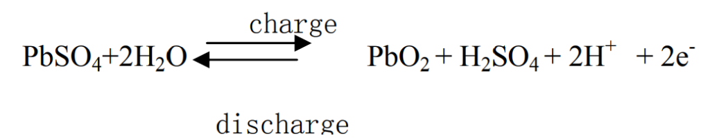
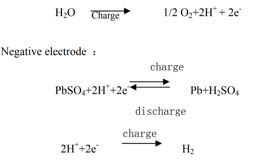
- Simultaneously, some of the released protons and electrons combine with water to form oxygen (O2) and additional protons.
Negative Electrode (Anode):
- During Charging:
- Lead sulfate (PbSO4) at the negative electrode reacts with protons (H+) and electrons (2e-) to form lead (Pb) and sulfuric acid (H2SO4).
- Simultaneously, protons and electrons combine to form hydrogen gas (H2).
These chemical reactions occur during the charging process, converting electrical energy into chemical energy stored within the battery.
During discharging, the reverse reactions take place, converting the stored chemical energy back into electrical energy. Electrons flow from the negative electrode to the positive electrode through an external circuit, producing electrical current.
One of the key advantages of VRLA batteries is their ability to recombine the oxygen produced at the positive electrode with the hydrogen produced at the negative electrode, preventing the escape of these gases from the battery. This internal recombination process helps maintain the integrity of the sealed design and prevents the need for adding water or acid to the battery, making VRLA batteries maintenance-free.
Oxygen cycle principle
The oxygen cycle principle in VRLA (Valve Regulated Lead-Acid) batteries plays a crucial role in maintaining their sealed and maintenance-free design while preventing water loss and the need for acid or water additions during use. This principle is achieved through the design of excessive active material at the negative electrode and the use of specific materials and structures within the battery.
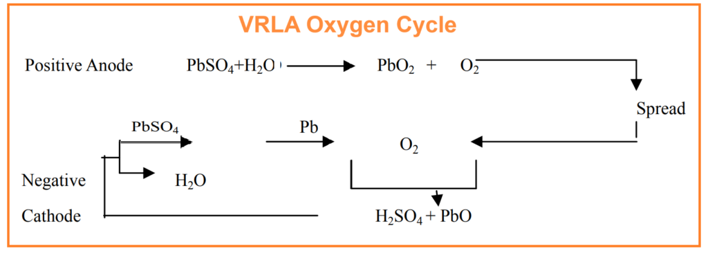
Here’s a breakdown of the oxygen cycle principle:
- Late-Stage Charging and Oxygen Production: During the later stages of charging or overcharging, oxygen is produced at the positive electrode (cathode) as a byproduct of the chemical reactions occurring within the battery.
- Oxygen Migration to the Negative Electrode: In VRLA batteries, the oxygen generated at the positive electrode must migrate to the negative electrode to facilitate complex chemical reactions. This migration of oxygen occurs through two main mechanisms:
- Dissolution in Electrolyte: Some of the oxygen dissolves in the electrolyte, allowing it to reach the surface of the negative electrode through diffusion in the liquid phase.
- Vapor Diffusion: Oxygen also moves in the form of vapor through open channels or voids within the battery to reach the negative electrode surface. This vapor diffusion is more efficient than liquid-phase diffusion and significantly contributes to the oxygen cycle.
- Negative Electrode’s Dual Role: The negative electrode plays a dual role during this process:
- Reaction with Oxygen: The spongy lead of the negative electrode reacts with the incoming oxygen, which leads to the oxidation of lead into lead oxide.
- Reduction of Lead Sulfate: Simultaneously, the lead sulfate present on the negative electrode receives electrons from the external circuit, allowing for the reduction reaction that converts lead sulfate back into spongy lead.
- Efficiency of Oxygen Recombination:
- AGM Battery: AGM batteries have a highly efficient oxygen recombination process, with recombination efficiencies of up to 99% in a poor liquid state.
- Gel Battery: Gel batteries have relatively lower oxygen recombination efficiency compared to AGM batteries, typically ranging from 70% to 90% in a dry state.
- Flooded Battery: Traditional flooded batteries do not create an effective oxygen recombination reaction, resulting in almost zero sealing reaction efficiency.
The efficient oxygen cycle in VRLA batteries, especially in AGM batteries, allows for the recombination of oxygen with other elements within the battery, preventing the loss of water and ensuring that the battery remains sealed and maintenance-free. This design feature makes VRLA batteries suitable for a wide range of applications where water maintenance is not feasible.
VRLA Codes and Standards:
Fixed type VRLA (Valve Regulated Lead-Acid) batteries are subject to various national and international standards and regulations to ensure their safety, performance, and quality. Compliance with these standards is essential for manufacturers and users of VRLA batteries. Here are some of the key standards that fixed type VRLA batteries should adhere to:
- BS6290-1987: The British Standard BS6290-1987 sets guidelines for stationary lead-acid batteries with valve-regulated norms. It specifies requirements and testing procedures for such batteries, including VRLA types.
- JIS C 8707-1992: This is the Japanese Industrial Standard for cathode absorption seal stationary lead-acid batteries. It outlines requirements and standards for VRLA batteries used in stationary applications.
- IEC 60896-21: The International Electrotechnical Commission (IEC) standard 60896-21, titled “Stationary lead-acid battery (VRLA),” provides international guidelines for VRLA batteries. It is a comprehensive standard that covers various aspects of VRLA battery design, performance, and testing. Compliance with IEC standards ensures that VRLA batteries meet international quality and safety criteria.
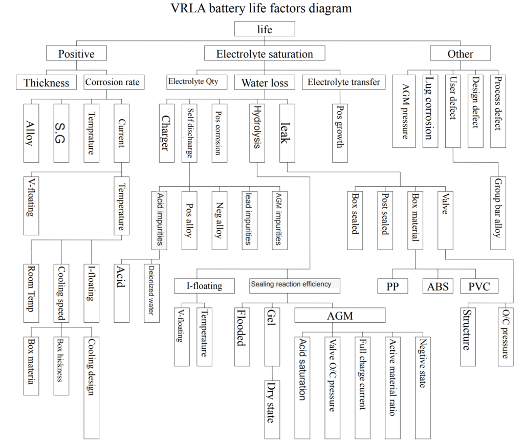
VRLA Battery life factors:
Related Articles:
VRLA (Valve Regulated Lead Acid) Battery Design.
What is Float Charge in Battery? Float Voltage.
What is Battery Capacity Calculation? Calculation for VRLA Battery.
Failure Modes of VRLA Battery.
What are Factors Effect VRLA Battery Capacity?
Cause of Self Discharging of Batteries.
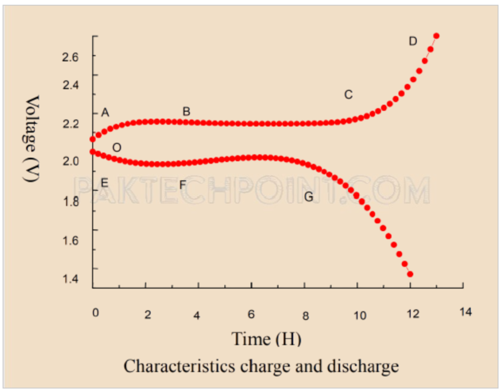
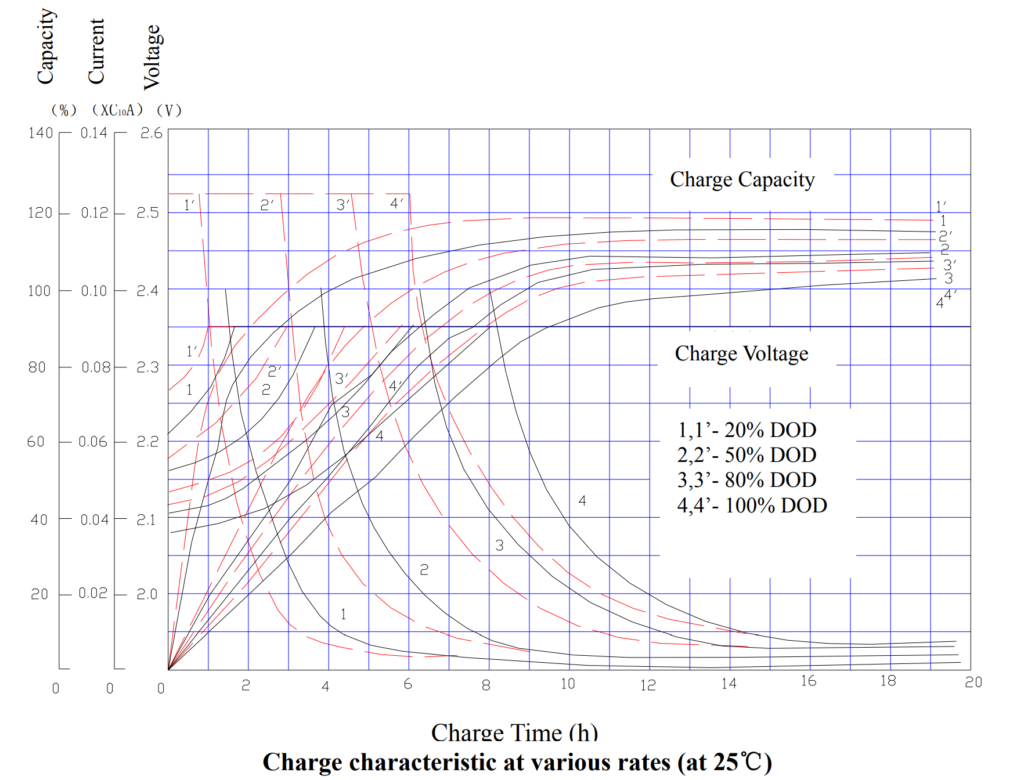
Characteristics of VRLA battery charge and discharge
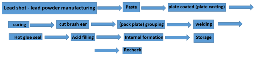
VRLA battery manufacturing process
What is the Peukert effect, and how does it impact VRLA battery performance?
How does temperature compensation work in VRLA batteries, and why is it essential for optimal performance?
What are the main differences between AGM (Absorbent Glass Mat) and Gel VRLA batteries, and how do these differences affect their capacity and application suitability?
What are the key factors and considerations for determining the optimal float voltage settings in VRLA batteries, and how do these settings affect capacity and battery life?
How does internal resistance impact VRLA battery capacity and performance, and what techniques or technologies are used to mitigate internal resistance effects in high-rate discharge applications?
Discover more from PAKTECHPOINT
Subscribe to get the latest posts sent to your email.