VOR, or VHF Omnidirectional Range, is a type of short-range radio navigation system used by aircraft for navigation. It operates in the Very High Frequency (VHF) band and provides pilots with azimuth information, allowing them to determine their radial position relative to the VOR ground station. VOR stations transmit signals in all directions, and the aircraft’s VOR receiver measures the phase difference between these signals to determine the aircraft’s radial from the station. This information helps pilots establish their position and navigate along desired routes, making VOR a critical component of air navigation systems, particularly in areas where GPS coverage may be limited or unreliable.
What is VHF Omnidirectional Range?
VOR, or VHF Omnidirectional Range, is a type of radio navigation system used by aircraft to figure out their position and direction. It works by picking up VHF radio signals sent out by fixed ground stations. Developed during World War II and deployed by 1946, VORs have been a crucial part of air navigation ever since. They’re like old-school signposts in the sky, helping pilots find their way along air routes. Despite predictions that newer GPS systems would replace them, VORs are still widely used today in both commercial and private aviation.
The process of determining a fix or direction using VOR information is similar to what was explained for NDBs. However, VOR signals offer much better accuracy (around 90 meters) and reliability compared to NDBs due to several factors. VHF radio signals used by VORs are less prone to bending around terrain and coastlines, and phase encoding suffers less interference from thunderstorms. VOR stations often have DME or military TACAN equipment co-located with them. When a VOR and TACAN are co-located, it’s called a VORTAC, and when only DME is co-located, it’s called a VOR-DME. A VOR radial combined with DME distance allows for a position fix using just one station. VOR-DMEs and TACANs share the same DME system, and different symbols are used to identify these co-located systems.

A VOR ground station emits two signals: an omnidirectional signal and a highly directional signal that varies in phase 30 times a second compared to the omnidirectional signal. By comparing the phase of the directional signal to the omnidirectional one, the angle or bearing formed by the aircraft and the station can be determined. This line of position is called the “radial” from the VOR.
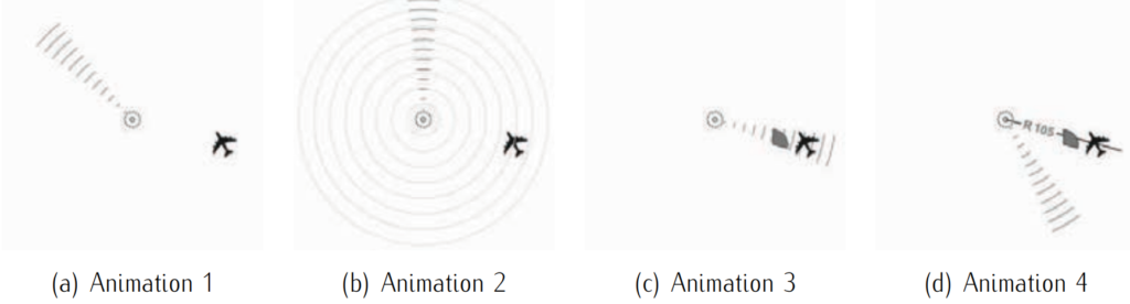
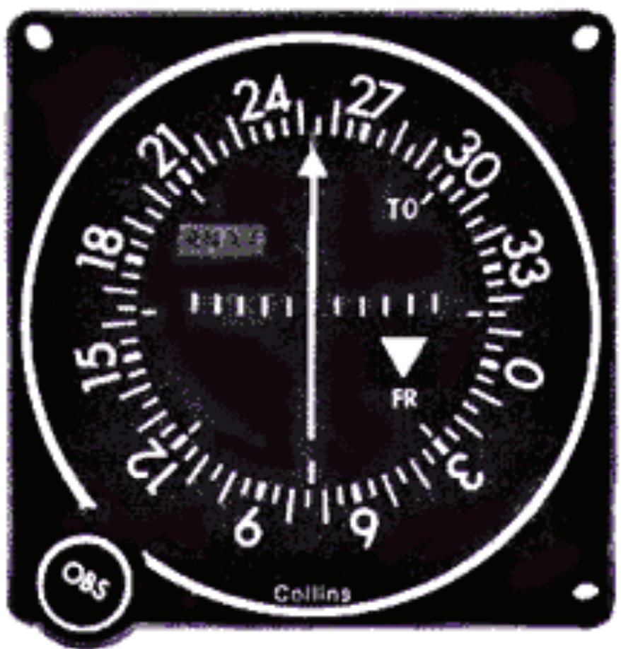
The bearing is then displayed in the aircraft cockpit using one of the following four common types of indicators:
- The Omni-Bearing Indicator (OBI) is a common VOR indicator used in light aircraft. It includes an Omni Bearing Selector (OBS) knob and scale to set the desired course. A Course Deviation Indicator (CDI) shows the aircraft’s deviation from the selected course, while a TO-FROM indicator indicates whether the course leads to or away from the VOR station.
- The Radio Magnetic Indicator (RMI) displays the aircraft’s current heading and the radial from the VOR station. The course arrow on the rotating card indicates the radial, while the arrow’s tail points to the station and its head indicates the inverse course.
- The Horizontal Situation Indicator (HSI) is a more advanced VOR indicator that integrates heading information with a navigation display, resembling a simplified moving map for easier navigation.
- An Area Navigation (RNAV) system is an onboard computer with a display and navigation database. It requires at least two VOR stations (or one VOR/DME station) to plot the aircraft’s position on a moving map, displaying course deviation relative to VOR stations or waypoints.
VOR displays interpretation.

The scanning beam technique involves focusing electromagnetic waves in a specific direction, typically achieved using large antennas and high frequencies. Two key navigational aids that utilize this technique are the Microwave Landing System (MLS) and Radar (Radio Detection and Ranging). MLS facilitates precision landing, while radar serves various purposes including aircraft detection, navigation, and weather monitoring through the emission and reception of radio signals.