The layout of an aircraft cockpit is carefully designed to provide the pilot with all the necessary instruments and controls to operate the aircraft safely and efficiently. While cockpit layouts can vary depending on the type of aircraft, they generally include the following components:

Aircraft Cockpit Layout
- Primary Flight Instruments: These instruments provide essential information about the aircraft’s attitude, altitude, airspeed, and heading. They typically include:
- Attitude Indicator (Artificial Horizon)
- Altimeter
- Airspeed Indicator
- Heading Indicator (Directional Gyro)
- Vertical Speed Indicator (Variometer)
- Navigation Instruments: These instruments help the pilot navigate the aircraft accurately. They may include:
- GPS Navigation Display
- VOR (VHF Omnidirectional Range) Receiver
- ADF (Automatic Direction Finder)
- DME (Distance Measuring Equipment)
- Engine Instruments: These instruments provide information about the aircraft’s engines, including:
- Tachometer (Engine RPM)
- Oil Temperature and Pressure
- Fuel Flow and Pressure
- EGT (Exhaust Gas Temperature)
- Turbine Inlet Temperature (for jet engines)
- Control Panels: These panels contain switches, knobs, and levers for controlling various aircraft systems, such as:
- Electrical Systems
- Communication and Navigation Radios
- Lighting Systems
- Environmental Controls (e.g., heating and ventilation)
- Fuel System Controls
- Secondary Instruments and Displays: Depending on the aircraft’s complexity, there may be additional instruments and displays for specific functions, such as:
- Weather Radar Display.
- Traffic Collision Avoidance System (TCAS) Display.
- Engine Management Systems.
- Multi-Function Displays (MFDs) for displaying various information simultaneously.
- Seats and Controls: The cockpit typically includes seating for the pilot and co-pilot, along with adjustable seats and controls for comfort and ergonomic purposes. Controls may include:
- Control Yokes or Side Sticks for aircraft control
- Rudder Pedals for controlling the aircraft’s yaw
- Throttle Levers for engine power control
- Flap and Trim Controls
Overall, the layout of the cockpit is designed to provide the pilot with easy access to critical information and controls, allowing for safe and efficient operation of the aircraft in various flight conditions.
Aircraft Cockpit Layout
The cockpit, also known as the flight deck, is where the pilot and co-pilots command the aircraft. It’s typically located in the nose of the aircraft and is separated from the cabin. In modern cockpits, you’ll find flight instruments on an instrument panel and controls that allow the pilot to maneuver the aircraft. These controls include the control yoke (or control column) for adjusting the elevator and ailerons, pedals for controlling the rudder, and throttle levers for adjusting thrust.
The layout of cockpits in modern airliners is quite standardized. Most systems-related controls, like switches, are located on an overhead panel in the ceiling. These controls manage various systems such as the electric, fuel, hydraulic, and pressurization systems. Radio communication systems are typically found on a panel between the pilot’s seats, known as the pedestal.
The instrument panel or display is positioned in front of the pilots for easy visibility. In electronic cockpits, essential displays include the Mode Control Panel (MCP), Primary Flight Display (PFD), Navigation Display (ND), Engine Indicator and Crew Alerting System (EICAS), and Flight Management System (FMS), along with backup instruments. These displays provide crucial information for flight and navigation. Traditional mechanical instruments have been replaced by electronic displays, leading to the term “avionics systems” for the electronics onboard the aircraft.
1. Mode Control Panel (MCP)
2. Primary Flight Display (PFD):
The Primary Flight Display (PFD) is a crucial component of modern aircraft cockpits, providing pilots with essential flight information in a clear and concise format. Unlike traditional instrument setups, the PFD integrates multiple flight instruments into a single electronic display, streamlining the pilot’s workflow and enhancing situational awareness.
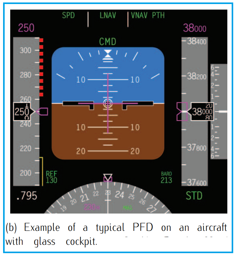
Located prominently in the cockpit, typically at the center for easy viewing, the PFD presents a digitized representation of key flight parameters. These include:
- Attitude Indicator (Artificial Horizon): Displays the aircraft’s pitch and roll attitude relative to the horizon, enabling pilots to maintain proper aircraft orientation.
- Airspeed Indicator: Indicates the aircraft’s airspeed, essential for controlling aircraft performance and adhering to speed limits.
- Altitude Indicator: Shows the aircraft’s current altitude above sea level, crucial for maintaining proper clearance from terrain and other aircraft.
- Vertical Speed Indicator (Variometer): Provides information about the aircraft’s rate of climb or descent, helping pilots maintain desired altitude changes smoothly.
- Heading Indicator: Optionally included in some PFDs, it displays the aircraft’s current heading, aiding navigation and orientation.
- ILS/VOR Deviation Indicators (CDI): Indicates the aircraft’s deviation from the desired course when flying instrument approaches or navigating using VOR stations.
3. Navigation Display (ND):
The Navigation Display (ND) is a critical component of the modern aircraft cockpit, providing pilots with essential navigational information in an electronic format. Positioned within the cockpit for easy access, the ND offers a wealth of data to assist pilots in navigating their route efficiently and safely.
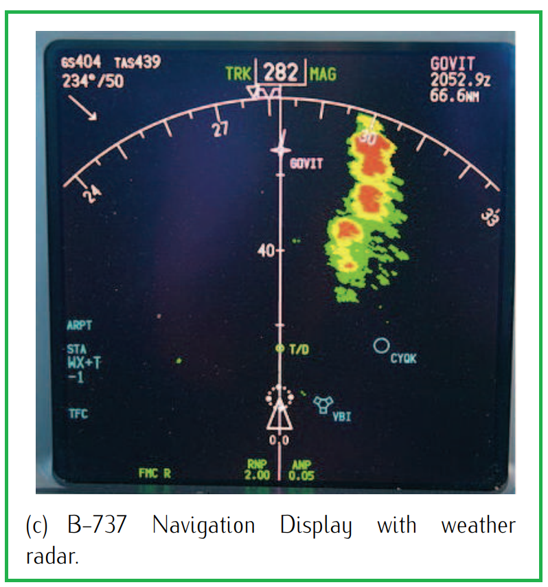
Key features of the Navigation Display include:
- Route Information: The ND displays the planned route of the aircraft, including waypoints, airways, and other navigational points. This allows pilots to visualize their intended flight path and make any necessary adjustments.
- Next Waypoint Data: Pilots can view information about the next waypoint along their route, including distance, estimated time to arrival, and course deviation information.
- Wind Speed and Direction: The ND provides real-time data on wind speed and direction, allowing pilots to account for wind effects and adjust their flight plan accordingly.
- Meteorological Data: In addition to basic weather information, such as current conditions and forecasts, the ND can display data on incoming storms or adverse weather conditions along the flight path.
- Navigational Aids: The ND indicates the location of ground-based navigational aids, such as VOR (VHF Omnidirectional Range) stations and NDB (Non-Directional Beacon) transmitters, which assist pilots in navigation and orientation.
4. Engine Indication and Crew Alerting System (EICAS) or Electronic Centralized Aircraft Monitor (ECAM)
The Engine Indication and Crew Alerting System (EICAS), used by Boeing, and the Electronic Centralized Aircraft Monitor (ECAM), used by Airbus, are advanced systems that provide critical information about an aircraft’s various systems to the flight crew. These systems play a crucial role in monitoring the health and performance of the aircraft during flight.
EICAS/ECAM displays offer a comprehensive overview of key systems, including:
- Propulsion Systems: Information about the engines, such as engine parameters, fuel flow, temperature, and pressure, is displayed to ensure optimal engine performance and detect any anomalies.
- Fuel System: The status of the fuel system, including fuel quantity, temperature, and flow, is monitored to ensure sufficient fuel supply and to detect any fuel-related issues.
- Electrical System: The electrical system’s status, including battery voltage, generator output, and electrical load, is monitored to ensure proper electrical power distribution and to identify any electrical malfunctions.
- Environmental Control Systems: Information about cabin and cockpit temperature, pressure, and ventilation is displayed to maintain a comfortable and safe environment for passengers and crew.
- Control Surfaces: The position and status of control surfaces, such as flaps, slats, and spoilers, are monitored to ensure proper aerodynamic control and to detect any failures or malfunctions.
The EICAS/ECAM display allows pilots to select and view specific information by pressing buttons or accessing menu options. This customizable feature enables pilots to focus on relevant data based on the current phase of flight or any specific issues that may arise.
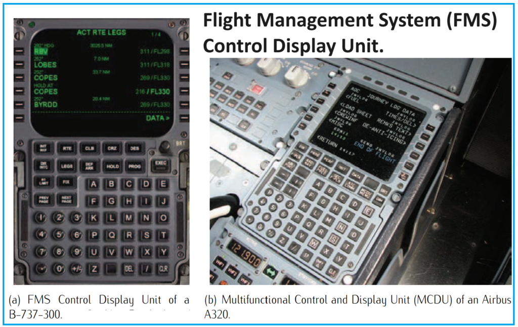
5. Flight Management System (FMS):
The Flight Management System (FMS) is a sophisticated computer system designed to automate various in-flight tasks, thereby reducing the workload on the flight crew and enhancing operational efficiency. Its primary role is to manage the aircraft’s flight plan, which is inputted before departure and updated during the flight through data-link communications.
One of the key functions of the FMS is to guide the aircraft along its predetermined flight path. It achieves this by continuously monitoring the aircraft’s current state, including its position, velocity, and heading angle, and comparing this information with the desired parameters outlined in the flight plan. Based on this comparison, the FMS calculates and implements a guidance law to ensure the aircraft stays on course.
In the cockpit, the FMS is typically accessed and controlled through a device known as the Control Display Unit (CDU). The CDU features a small screen and either a keyboard or touchscreen interface, allowing the flight crew to interact with the FMS and input commands or adjustments as needed.
The FMS communicates with other onboard systems, such as the Navigation Display (ND) and other electronic displays, to relay important flight plan information. This includes details about waypoints, altitudes, speeds, bearings, and navigational aids, which are presented to the flight crew in a user-friendly format on the displays.