This article is about general, Functional and Technical Specification used in Integrated Automation System or Building Automation System.
Building Automation System Functional and Technical Specification
-
Electrical Power Meter Monitoring System:
- The electrical power monitoring system shall be provided with communication capabilities to be integrated into the IAS through the FACLAN building network. Communication systems shall be non-proprietary open systems such as BACnet or Modbus.
- In occupancy mode, the electrical power monitoring system shall be engaged.
- In un-occupancy mode, the electrical power monitoring system shall be engaged.
- In emergency mode, the electrical power monitoring system shall be engaged, unless the facility experiences a power outage.
-
Lighting Control System:
- The lighting control system shall be provided with communication capabilities to be integrated into the IAS through the FACLAN building network. Communication systems shall be non-proprietary open systems such as BACnet or Modbus. System shall share the following data:
- Read device (DALI device) status
- Read Lamp status
- Read Light level
- Read what override is active
- Send override to a device
- Set override type (high priority, normal)
- Set light level
- Set duration
- Calling Preset DALI scene
- Set scene ID
- Set duration for a scene
- Set scene level
- Read lights on/off status for a group of fixtures
- Send override to a group of fixtures
- Set light level for a group of fixtures
- Read ballast status for a group of fixtures
- Read lamp status for a group of fixtures
- Read power consumption for a group of fixtures
- Set Light level for a group of fixtures via scenes
- Set the priority of the override command sent to a group of fixtures
- Read occupancy sensor status
- Read daylight sensor reading
- In occupancy mode, the lighting control system shall be engaged. In addition to the aforementioned, the following will be conducted in occupancy mode;
- Upon the identified vacancy of a tenant, the HVAC control system shall initiate a demand control ventilation (calculated OA CFM) program based on number of occupants present in an large occupied HVAC zones (non-office or large open office).
- During Demand Response – Level 1, the public area, back of house and corridor lighting shall be dimmed by 15%.
- During Demand Response – Level 2, the public area, back of house and corridor lighting shall be dimmed by 15%.
- During Demand Response – Level 3, the office lighting shall be dimmed by 15%.
- In un-occupancy mode, the lighting control system shall be disengaged and placed in standby, as only essential security offices and areas shall remain illuminated. The following will be conducted in un-occupancy mode;
- The lighting control shall be engaged during temporary occupancy and shall remain on for a pre-determined duration of time.
- In emergency mode, the lighting control system shall be engaged. The following will be conducted in emergency mode;
- All lighting levels and set points will be over-ridden and turned on at100%.
- The lighting control system shall be provided with communication capabilities to be integrated into the IAS through the FACLAN building network. Communication systems shall be non-proprietary open systems such as BACnet or Modbus. System shall share the following data:
-
Plug Load Control System:
- The plug load control system shall be provided with communication capabilities to be integrated into the IAS through the FACLAN building network. Communication systems shall be non-proprietary open systems such as BACnet or Modbus. System shall share the following data:
- Read device (DALI device) status
- Read plug status
- Read what override is active
- Send override to a device
- Set override type (high priority, normal)
- Set status (on or off)
- Set duration
- Read plug on/off status for a group of plugs
- Send override to a group of plugs
- Read status for a group of plugs
- Read power consumption for a group of plugs
- Set the priority of the override command sent to a group of plugs
- In occupancy mode, the plug load control system shall be engaged. In addition to the aforementioned, the following will be conducted in occupancy mode;
- During Demand Response – Level 1, the public area plugs shall be shut off.
- During Demand Response – Level 2, the back of house plugs shall be shut off.
- During Demand Response – Level 3, the office non-critical plugs shall be shut off.
- In un-occupancy mode, the plug load control system shall be disengaged and placed in standby, as only essential areas and critical plug loads shall be powered.
- In emergency mode, the plug load control system shall be engaged and enabled.
- The plug load control system shall be provided with communication capabilities to be integrated into the IAS through the FACLAN building network. Communication systems shall be non-proprietary open systems such as BACnet or Modbus. System shall share the following data:
-
Emergency Generator and UPS systems:
- The emergency generator shall be provided with communication capabilities to be integrated into the IAS through the FACLAN building network. Communication systems shall be non-proprietary open systems such as BACnet or Modbus. The system shall share the following information/data with the IAS;
- Kwh and kW from generators time stamped in 15 minute instances.
- Starts and runtime.
- Battery voltage.
- Fuel tank level.
- Radiator and oil temperatures.
- Percent of full load power production.
- Volts, amps, hertz, power factor.
- Alarm or fault occurrences (failure, fuel loss, power loss, communication loss).
- In occupancy mode, the emergency generator shall be disengaged unless the unit is manually operated.
- In un-occupancy mode, the emergency generator shall be disengaged unless the unit is manually operated.
- In emergency mode, the emergency generator shall be engaged in the event the facility experiences a power outage.
- The emergency generator shall be provided with communication capabilities to be integrated into the IAS through the FACLAN building network. Communication systems shall be non-proprietary open systems such as BACnet or Modbus. The system shall share the following information/data with the IAS;
-
GRAPHICAL EXAMPLES
- This section can be included as is or as an attachment. The graphics should be reviewed and updated as examples of what the engineer would expect as a deliverable.
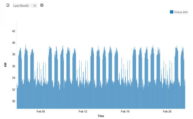
- Provide graphical diagrams which assist with analytics such as a weekly diagram with color coded times of day to show values:
- This section can be included as is or as an attachment. The graphics should be reviewed and updated as examples of what the engineer would expect as a deliverable.

Software shall show power use profiles in multiple formats.
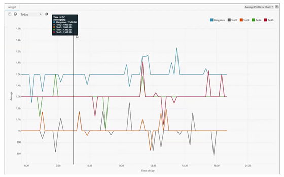
Multiple values can be overlaid on a graph for comparison.
The software shall show equipment operation in chart form.

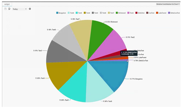
Software should be able to provide relative contribution charts.
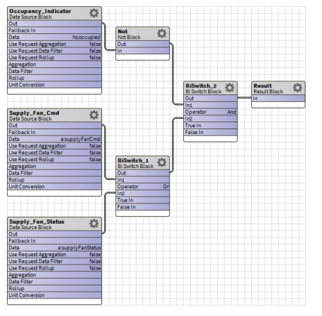
Software shall provide flowcharts and linked programming algorithms.
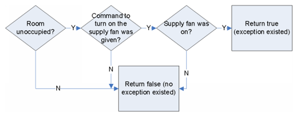
This is an example of the graphical programming algorithms.
HVAC System Functional Specification | Integrated Automation System
Water Booster Pump Control System Functional Specification