Transducers and Instrumentation for Vibration Measurement and Monitoring of Rolling Element Bearings

Transducers and Instrumentation for Vibration Measurement and Monitoring of Rolling Element Bearings

1. REBAM Instrumentation System

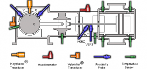
Rolling Element Bearing Activity Monitor. The REBAM system uses a high-gain, low-noise eddy current proximity transducer that is installed in the bearing housing observing the bearing outer ring. 


Transducers and Instrumentation for Vibration Measurement and Monitoring of Rolling Element Bearings

The bearing outer ring contains the outer race. The REBAM® transducer measures the very small (microinch/micrometre) deflection of the outer ring as the rolling elements pass the area observed by the transducer. These deflections are measured in terms of displacement. The operating frequency range for the REBAM® transducer system is from 0 Hz (dc) to 10 kHz (0 to 600 kcpm). The REBAM® system is a direct and very sensitive method of rolling element bearing measurement. It offers a very high signal-to-noise ratio, as compared to casing-mounted acceleration or velocity measurements.

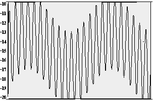
Through the use of electronic filters, the REBAM® vibration signal is separated into Rotor Vibration and Prime Spike regions as previously discussed. Typical Prime Spike amplitudes are 10 to 50 microinches (0.25 to 1.3 micrometres) for a good bearing and 2 to 5 times that for a damaged bear-ing. However, the amplitude of the REBAM® signal is highly dependent upon the amount of loading on the elements as they pass the location of the probe, and it is, therefore, not possible to give broad guidelines for a healthy or a damaged bearing. A common practice is to take readings on what is known to be a healthy bearing and set the monitor Alert and Danger alarm levels at 1.5 and 2 times the baseline level. Field and lab tests confirm that using such alarm levels provides adequate failure protection.

2. Casing Vibration Instrument Systems
Rolling element bearing condition can be monitored by using casing measurements. Overall velocity or displacement, Prime Spike velocity, and the high frequency acceleration regions can be used. Bently Nevada can provide accelerometer or velocity transducer-based systems to monitor rolling element bearing condition. Overall casing velocity or displacement provides a means for determining the general mechanical condition of rolling element bearing machinery.

For a velocity transducer-based system, the frequency range used is from 10 Hz to 1 kHz (600 cpm to 60 kcpm). For an accelerometer-based system, the frequency range used is from 10 Hz to 20 kHz (600 cpm to 1.2 million cpm). Depending on the machine speed, the velocity system frequency range is likely to span the Rotor frequency region and the lower end of the Prime Spike frequency region. The acceleration system will cover the Rotor frequency region, Prime Spike region, and into the high frequency region.

As stated previously, the Prime Spike region is used by Bently Nevada to monitor the rolling element bearing-related frequencies (inner/outer race defects). By filtering out the rotor-related vibration signals (i.e., 1X, 2X, etc.), it is possible to get better signals related to the rolling element bearing condition. The Prime Spike frequency region includes thefundamental element passage frequency (EPx) and harmonics up to 7 EPx.

Read more

Predictive Maintenance through the Monitoring and Diagnostics of Rolling Element Bearings

Predictive Maintenance through the Monitoring and Diagnostics of Rolling Element Bearings

Introduction
The predictive maintenance philosophy of using vibration information to lower operating costs and increase machinery availability is gaining acceptance throughout industry. Since most of the machinery in a predictive maintenance program contains rolling element bearings, it is imperative to understand how to monitor and diagnose problems associated with them. Bently Nevada has adopted a two-part philosophy with regard to rolling element bearing monitoring and diagnostics: (1) the monitor system will provide adequate warning to avert catastrophic machine failures and (2) diagnostic data will be available so that when warning is given, the bearings will have visible damage. This philosophy should be kept in mind during the following discussion.

Rolling Element Bearing Characteristics
Any discussion of monitoring and diagnostics for rolling element bearings would not be complete without a comparison with the techniques used for fluid film bearings. The construction of a fluid film bearing is such that the shaft is supported by a fluid film during operation. By design, the shaft can experience motion relative to the bearing. Because of this freedom of motion, the industry-accepted vibration measurement for a fluid film bearing machine is a shaft relative measurement, i.e., proximity probe.

A rolling element bearing, by design, has extremely small clearances which do not allow a significant amount of shaft motion relative to the bearing (Figure 1).

Predictive Maintenance through the Monitoring and Diagnostics of Rolling Element Bearings


Forces from the shaft are transferred through the rolling elements to the bearing outer race and then ultimately to the bearing housing. Because of this transmission, a casing (bearing housing) measurement is normally acceptable for monitoring machines with rolling element bearings. However, as explained later in this discussion, a method called REBAM® is available from Bently Nevada Corporation that allows vibration measurements directly at the bearing outer ring, which contains the outer race. This direct measurement greatly enhances bearing vibration data, and in some cases, this is the only measurement that can provide adequate vibration information.(Reference Hansen, J. Seven and Harker, Roger G., ”A New Method for Rolling Element Bearing Monitoring in the Petrochemical Industry,” Presented at the Vibration Institute Seminar, New Orleans, Lousiana, June 1984.) Shaft relative vibration measurements (i.e., proximity probe) are also useful when clearances increase during failure and for observation of rotor problems that are not related to bearings. A classical characteristic of rolling element bearings is the generation of specific vibration frequencies based on the bearing geometry, number of rolling elements and the speed at which the bearing is rotating Click to lik to read terms of frequencies in vibration. (Reference Foiles, Bill, “Rolling Element Bearing Frequencies,: Edited by Bently Nevada Corporation.)

The most prominent of these characteristic bearing frequencies are the Outer Race Element Pass frequency, Inner Race Element Pass frequency, Element Spin frequency, and the Fundamental Train frequency or Cage frequency. These vibrational components are generated even in a new bearing, but the amplitudes are small. Bently Nevada defines the frequency range from the Outer Race Element Pass frequency (1EPx) to seven times this value (7EPx) as the Prime Spike frequency region. This range contains the Inner and Outer Race Element Pass and Element Spin frequencies, and is therefore a valuable region to monitor bearing condition. The Cage frequency lies below 1/2 rotor speed (for a stationary outer ring) and cage damage would therefore show up in the Rotor frequency region, defined below. Distinguishing between these two regions enhances the ability to determine if a vibration increase is caused by a failing bearing or a rotor-related malfunction (imbalance, misalignment, fluid induced instability, etc.). It should be kept in mind that, from a plant manager’s point of view, it is much more important to determine when a bearing needs to be replaced to avert a machine failure and unnecessary downtime, than it is to determine what components within the bearing are being damaged. The primary goal of a rolling element bearing monitoring system is to satisfy this need. The secondary goal is to provide data that is appropriate for diagnosing the failure of the bearing with the purpose of determining the root cause (improper mounting, lubrication, loading, etc.) so that similar failures can be avoided in the future.

Read more

Rolling Element Bearing Frequencies Derivation of Bearing Frequencies


The topic is about Rolling Element Bearing Frequencies Derivation of Bearing Frequencies.Primary Rolling Element Bearing Frequencies. Cage Frequency. Race Ball Pass Frequency.

Rolling Element Bearing Frequencies

These calculated frequencies are essentially of academic interest, because (1) it frequently occurs that any flaw on any element rapidly generates secondary flaws on other elements and (2) knowledge of the existence and extent of a flaw is vital; however, the element that it is on is not too important because the entire rolling element bearing is normally replaced and not just the damaged portion.

Rolling element bearings find many uses in today’s machinery. They can be found in motors, slow-speed rollers, gas turbines, pumps, and many other machines. Some of the reasons rolling element bearings are used are: low starting friction, low operating friction, ability to support loads at low (even zero) speed, lower sensitivity to lubrication (compared to fluid film bearings, thus a simpler lubrication system can often be used), and the ability to support both radial and axial loads in the same bearing. When some of these factors are important, rolling element bearings may be in use.


By themselves, rolling element bearings have very little damping, so whenever a machine with rolling element bearings traverses a balance resonance, large vibration can result. Also, compared to fluid film bearings which generally have a long life, rolling element bearings have a limited fatigue life due to the repeated stresses involved in their normal use.

Rolling element bearings, regardless of type (ball, cylindrical, spherical, tapered, or needle) consist of an inner and outer race separated by the rolling elements, which are usually held in a cage (see Figure.

Rolling Element Bearing Frequencies

Mechanical flaws may develop on any of these components. Using the basic geometry of a bearing, the fundamental frequencies generated by these flaws can be determined.

For most applications, the outer race is fixed and does not rotate. However, in some instances, just the outer race or both races rotate. For the case of the outer race fixed, Following figure contains a summary of the main bearing frequencies. These frequencies may, and often do, include sum and difference frequencies. Often they are modulated by the speed of the equipment.

Rolling Element Bearing Frequencies

Read more

WHAT IS CONTROL VALVE HANDBOOK DOWNLOAD

This article is about WHAT IS CONTROL VALVE HANDBOOK DOWNLOAD and focusing to the engineers, technicians and supervisors. You will find lot of documents related to this article. Just navigate our website  www.paktechpoint.com  and find more articles. Please! Do not forget to subscribe our You tube channel also. Thanks in Advance.

PLEASE SUBSCRIBE OUR PAKTECHPOINT YOUTUBE CHANNEL


Wait some time if Book is not loaded…………….!


Emerson-Control-Valve-HandBook

WHAT IS CONTROL VALVE HANDBOOK DOWNLOAD

This book is offering details as mentioned following chapter wise.

In First Chapter of this book offers Introduction to Control Valves

In 2nd Chapter of this book includes information Control Valve Performance

In 3rd Chapter of this book covers Valve and Actuator Types

In 4th Chapter of this book is comprehensive guide to Control Valve Accessories

In 5th Chapter of this book describes Control Valve Selection

In 6th Chapter of this book develops Special Control Valves

In 7th chapter of this is discussing about Steam Conditioning Valves

In 8th chapter of this book gives information about Installation and Maintenance

In 9th chapter of this book illustrates about Standards and Approvals

In 10th chapter of this book explains about Engineering Data about control valve.

WHAT IS CONTROL VALVE HANDBOOK DOWNLOAD

Read more

What is REBAM How the REBAM Concept Works and Field Application of REBAM

How the REBAM Concept Works and Field Application of REBAM

Introduction
The ability to monitor and analyze machinery utilizing rolling element bearings is a unique challenge. Most monitoring and analysis techniques used today use a casing vibration instrumentation system to determine rolling element bearing condition. Due to problems introduced by either the instrumentation itself or by interference for extraneous vibration, limited success has been achieved. The purpose of this applications note is to outline how vibration measurements made directly at the bearing outer ring, which contains the outer race, can greatly improve the ability to monitor and analyze rolling element bearing condition.

How the REBAM Concept Works

The concept of measuring the deflections of a rolling element bearing outer ring during operation was originally demonstrated by Shapiro of the Franklin Institute using strain gages attached to the bearing’s outer ring. This concept was further improved upon by G. J. Phillips of the David W. Taylor Naval Research and Development Center using noncontact fiber optic techniques. Bently Nevada Corporation adopted this noncontact concept and, as an alternative to the fiber optic sensor, developed a high-gain, low-noise eddy current proximity transducer to measure the deflections of a rolling element bearing’s outer ring. This transducer is called REBAM®, which is an acronym for Rolling Element Bearing Activity Monitor.

A high-gain eddy current proximity transducer is mounted through the bearing housing observing the external surface of the bearing outer ring (Figure 1). The bearing outer ring contains the bearing’s outer race. During bearing operation, the bearing’s outer ring deflects minutely as a function of applied forces. The REBAM® transducer measures the very small (microinch/micrometre) deflections are measured in terms of displacement and are typically in the range of 2 to 300 microinces (0.5 to 8 micrometres). Under typical operating conditions, the signal from a good bearing, observed on an oscilloscope, displays a smooth signal with few or no “spikes” of significant amplitude. When an internal bearing flaw (e.g. , inner race, outer race, rolling elements) is present, “spikes” of significant amplitude occur on the vibration signal (Figure 2). In order to clarify how the REBAM® signal can be used to evaluate rolling element bearing condition, some discussion of rolling element bearing vibration characteristics is justified.

What is REBAM

How the REBAM Concept Works

Rolling Element Bearing Vibration Characteristics
The vibrations produced by machines with rolling element bearings occur in three frequency regions: (1) Rotor Vibration region, (2) Prime Spike (element passage) region and (3) the High Frequency region. The High Frequency region measurement (above 5 Khz) is for specialized applications and will not be discussed in this applications note.

1. Rotor Vibration Region

Rotor-related vibration normally occurs in the range of 1/4 to 3 times shaft rotative speed (1/4Xx – 3x) and, when using the REBAM® instrumentation system, is measured in terms of displacement. Many rolling element bearing failures are the direct result of a rotor-related malfunction (e.g., unbalance, misalignment, or rotor instability). If the rotor-related vibration data is not monitored for identification and correction of rotor-related malfunctions, the bearing will chronically fail.

2. Prime Spike (Element Passage) Region
The second vibration frequency region to monitor for machines with rolling element bearings is the Prime Spike (element passage) region. A classical characteristic of rolling element bearings is the generation of specific frequencies based on the bearing geometry, number of rolling elements and the speed at which the bearing is rotating. These “bearing-related” frequencies are generated even by a new bearing, but the amplitudes are very small. Prime Spike is a term used by Bently Nevada to describe a vibration frequency range which includes those bearing frequencies that are generated by the rolling elements traversing either an inner or outer race flaw. This frequency range is normally 1 to 7 times the Outer Race Element Passage rate (1-7EPx). The Outer Race Element Passage rate (EPx) is defined as the rate at which the rolling elements pass a point on the outer bearing race.

Read more

Eddy Current Proximity Probes for Overspeed Protection Systems

Eddy Current Proximity Probes for Overspeed Protection Systems

Introduction
Since overspeed is one of the most dangerous conditions that can occur in a turbine, it is essential that overspeed protection systems are properly installed. In the sections below are issues you should consider when applying eddy current proximity transducers in an overspeed protection system.

A diagram shows the terms used in this document for describing gear geometry.

Signal Amplitude at Overspeed
The signal from a transducer system viewing a gear is a complex signal. In other words the signal may contain a vibration and/or runout component as well as the speed component in following figure. Other signal variations could come from inconsistencies in gear tooth dimensions. Normally these components of the signal are small compared to the speed component of the signal. However, when a machine approaches overspeed there must be no doubt which component of the signal represents the speed of the gear.

Signals from the transducer may contain a vibration and/or runout signal as well as a speed signal.

In order to insure that the speed signal is the dominant signal component, we recommend that the amplitude of the speed signal be greater than 7 Vpp at the overspeed setpoint (200 mV/mil transducer system).

The signal amplitude at overspeed is dependent on factors such as probe gap, gear dimensions, target material, and signal frequency. The general approach to estimating signal amplitude at overspeed is:


  1. Find the amplitude of the speed signal at slow roll.
  2. Estimate the amount of signal attenuation at the overspeed setpoint (frequency response).

Since the geometry of the gear affects both the slow roll signal amplitude and signal attenuation, the next section describes three types of gear geometry and shows the typical signal produced by each type.

Read more

error: Content is Protected.