The technical specification outlined in this article provides a comprehensive guide for the proper commissioning of liquid-filled transformers. Commissioning is a critical phase in the lifecycle of these transformers, ensuring that they are installed, configured, and tested to perform reliably and efficiently.
The article aims to establish clear work practices and guidelines to facilitate a successful commissioning process. However, it’s important to note that the article serves as a framework for understanding the essential steps and considerations involved in commissioning, rather than a detailed work scope.

What is Liquid Filled Transformer?
Liquid-filled transformers are essential components in electrical power distribution and transmission systems. They offer a reliable and efficient means of transforming voltage levels for efficient electricity transmission over long distances. These transformers utilize dielectric liquids such as mineral oil or silicone oil as both an insulating material and a coolant. The liquid provides excellent insulation properties, preventing electrical breakdown, and helps dissipate the heat generated during transformer operation. This cooling mechanism ensures that the transformer operates within safe temperature limits, maintaining its efficiency and extending its lifespan.
Liquid-filled transformers come in various sizes and voltage ratings, making them suitable for a wide range of applications, from substations to industrial facilities and utility grids. They consist of core and windings, enclosed within a sealed tank, which acts as a protective barrier against external environmental factors and prevents the escape of dielectric fluids. Additionally, some larger transformers feature a conservator and various accessories for monitoring and maintaining their performance. As the demand for efficient and reliable electrical power continues to grow, liquid-filled transformers remain a critical part of modern electricity infrastructure.
This specification serves as a comprehensive guideline for conducting inspections, tests, and commissioning procedures for liquid-filled transformers. It encompasses both visual and mechanical inspections, as well as electrical and functional testing. The document is a crucial reference point for professionals involved in ensuring the readiness and reliability of liquid-filled transformers for operation.
Testing and Commissioning of Liquid Filled Transformer
Upon receipt of the equipment, it is crucial to perform a series of inspections and checks to ensure the integrity and readiness of the electrical equipment for commissioning. Below is a detailed breakdown of these tasks, along with explanations of why they are important:
1. Inspect for Physical Damage:
- Shipping and handling can sometimes lead to physical damage. Identifying and reporting such damage ensures that necessary repairs or replacements are made promptly.
2. Verify Seismic Detectors (if applicable):
- Seismic detectors are vital for detecting ground motion during an earthquake. Ensuring they haven’t tripped is essential for earthquake preparedness.
3. Compare Nameplate Information:
- Comparing nameplate data with diagrams and specifications helps confirm that the equipment received matches what was ordered, reducing the risk of incorrect installations.
4. Verify Safety Grounding Cables:
- Safety grounding is critical for personnel safety. Checking cable connections and sizes ensures the protection of equipment and personnel from electrical faults.
5. Check for Oil Leaks:
- Oil leaks can compromise the performance and safety of electrical equipment. Early detection helps prevent potential oil-related issues.
6. Check Tank Pressure:
- Maintaining the correct tank pressure is essential for the operation of certain equipment. Monitoring pressure ensures equipment functions as designed.
7. Monitor Tank Pressure Regularly:
- Pressure fluctuations can indicate issues like leaks or malfunctioning components. Regular monitoring helps detect problems early.
8. Verify Tap Settings:
- Correct tap settings are essential to match the equipment’s voltage requirements. Incorrect settings can result in operational problems.
9. Confirm Proper Grounding:
- Proper grounding ensures electrical safety and equipment performance. Ensuring that the transformer frame and Wye connection are grounded reduces the risk of electrical faults.
10. Inspect Auxiliary Equipment:
Gauges, fans, and other auxiliary equipment contribute to the efficient operation of the transformer. Checking for damage ensures smooth operation.
11. Ensure Oil Flow:
Open valves are crucial for proper oil circulation in the cooling system. Confirming that all oil cooling system valves are open ensures efficient cooling.
12. Check Wiring Termination:
Tight and correctly wired terminations are essential for electrical connections. Proper wiring practices ensure reliable equipment performance.
13. Verify Level Placement:
Transformers need to be level to function correctly. Ensuring the equipment sits on a level plane via its foundations prevents operational issues.
14. Confirm Tap Charger Setting:
The tap charger setting must match the requirements for incoming voltages. Verifying that the mechanism is latched on the correct tap setting is essential.
15. Check Current Transformer Devices:
Ensuring that any shorting devices have been removed is critical for accurate current measurement. This check prevents measurement errors.
16. Inspect Ground Resistor:
Proper installation and connection of the ground resistor are vital for grounding systems. Recording the resistor value and conducting insulation-resistance tests ensure safety and functionality.
17. Verify Oil Levels:
Proper oil levels in bushings and tanks are essential for electrical insulation and cooling. This check prevents issues related to inadequate oil levels.
18. Ensure Proper Lightning Arrestor Placement:
Correct placement of pressure relief devices on lightning arrestors is crucial to prevent damage to adjacent equipment in the event of an arrestor failure.
19. Check Silica-Gel Condition (if applicable):
Silica gel is used for moisture control in conservation tanks. Ensuring its proper condition helps maintain the desired humidity levels.
By diligently performing these tasks, you ensure that the electrical equipment is in optimal condition and ready for commissioning, minimizing the risk of operational issues and ensuring safety standards are met.
Operational and Electrical Testing
Operational and Electrical Testing is a critical step in ensuring the performance, safety, and reliability of oil-filled transformers. Here’s a breakdown of the testing procedures and their importance:
1. Sweep Frequency Response Analysis (SFRA):
SFRA is used to assess the mechanical integrity of transformer windings. It helps identify issues such as winding deformations, shorted turns, or other mechanical faults.
2. Oil Dielectric Strength Test
This test evaluates the dielectric strength of the insulating oil. It ensures that the oil is capable of withstanding high voltage without breaking down, which is crucial for insulation.
3. Turn-to-Turn Ratio Test:
This test checks the turn-to-turn ratio of the transformer windings to ensure they are within acceptable limits. It helps detect winding faults or incorrect connections.
4. Insulation Power Factor (Doble) Bushing Test:
Bushings are essential for electrical insulation. This test assesses their insulation condition to prevent issues like partial discharge or dielectric breakdown.
5. Insulation-Resistance (Megger) Test:
Insulation resistance tests ensure the integrity of insulation materials. Testing primary and secondary windings, as well as cables, helps detect potential insulation faults.
6. Dissolved Gas Analysis (DGA):
DGA assesses the quality of the insulating oil by detecting dissolved gases. Abnormal gas levels can indicate incipient faults within the transformer.
7. Secondary-Injection Test on Relays:
Secondary-injection tests check the proper functioning of protective relays. It verifies that the relays can operate as intended during fault conditions.
8. Primary-Injection Test on Ground Current Transformers (50 GS Type):
This test ensures that the ground current transformers and associated wiring are functioning correctly. It verifies the integrity of the protective system.
9. Verify Current Transformer (C.T.) Ratios and Polarities:
Correct C.T. ratios and polarities are essential for accurate current measurement and protection coordination.
10. Function Test of Fans and Oil Pump:
Fans and oil pumps are critical for cooling and maintaining proper oil circulation. Calibrating and testing them ensures efficient cooling and operation.
11. Calibration and Function Test of Various Devices:
Calibrating and testing devices like low oil switches, flow switches, sudden pressure relief devices, oil temperature switches, and automatic nitrogen purge systems ensure their proper operation.
12. Verify Tap Settings and Secondary No-Load Voltage:
Confirming tap settings and secondary no-load voltage after energizing the unit ensures that the transformer is operating at the desired voltage levels.
13. Function Test of Alarm Devices:
Alarm devices are essential for monitoring the transformer’s condition. Testing them, including the alarm panel, ensures that potential issues are promptly detected and addressed.
By conducting these tests meticulously, you can identify any potential problems or faults in the transformer and its associated systems before energizing it. This proactive approach helps prevent equipment damage, ensures safety, and maintains reliable operation. Additionally, it aligns with best practices in transformer maintenance and commissioning.
Documentation
Proper documentation is essential for maintaining a record of the tests conducted and the condition of the transformer. Here’s a breakdown of the required documentation:
1. Nameplate Data and Test Results:
- This should include all relevant information from the transformer’s nameplate, such as its model, serial number, voltage ratings, and other specifications. Additionally, test results from the various inspections and tests conducted should be recorded and included in this documentation.
2. Report 1 – Power Transformer Test and Inspection Report:
- This report should detail all the tests and inspections performed on the power transformer. It should include the results of the Sweep Frequency Response Analysis (SFRA), oil dielectric strength test, turn-to-turn ratio test, and any other relevant tests. Additionally, it should provide information on visual and mechanical inspections. This report serves as a comprehensive record of the transformer’s condition.
3. Report 2 – Transformer Turns Ratio Test Report:
- This report should specifically focus on the turns ratio test. It should detail the test procedure, the results obtained, and any observations or findings related to the turns ratio. This information is critical for assessing the integrity of the transformer windings.
4. Report 3 – Transformer Insulation Power Factor Test Report:
- This report should cover the insulation power factor test conducted on the transformer. It should include the test conditions, equipment used, test results, and any analysis or interpretation of the power factor values. This test is essential for evaluating the insulation condition.
5. Report 4 – Autotransformer Test and Inspection Report:
- If an autotransformer is present, a separate report should be prepared for it. This report should mirror the format of Report 1 but focus specifically on the autotransformer. It should detail all tests and inspections conducted on the autotransformer, including visual, mechanical, and electrical tests.
6. Filing of Documentation:
- One copy of all completed documentation should be filed on-site for future reference. This provides a readily accessible record of the transformer’s condition and the tests conducted. Additionally, one copy of the documentation should be forwarded to the Electrical Engineering department for their records and analysis.
Proper documentation not only ensures that all necessary tests and inspections have been conducted but also serves as a valuable reference for future maintenance and assessments of the transformer’s condition. It is a crucial aspect of transformer commissioning and maintenance practices.
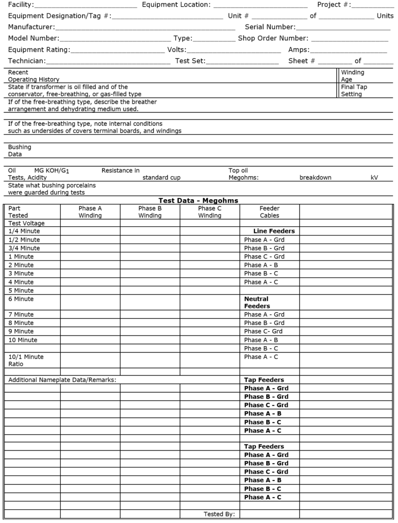
Power Transformer Test and Inspection Report
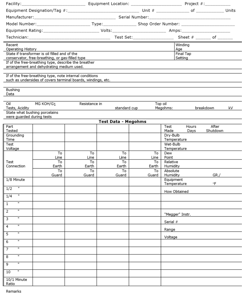
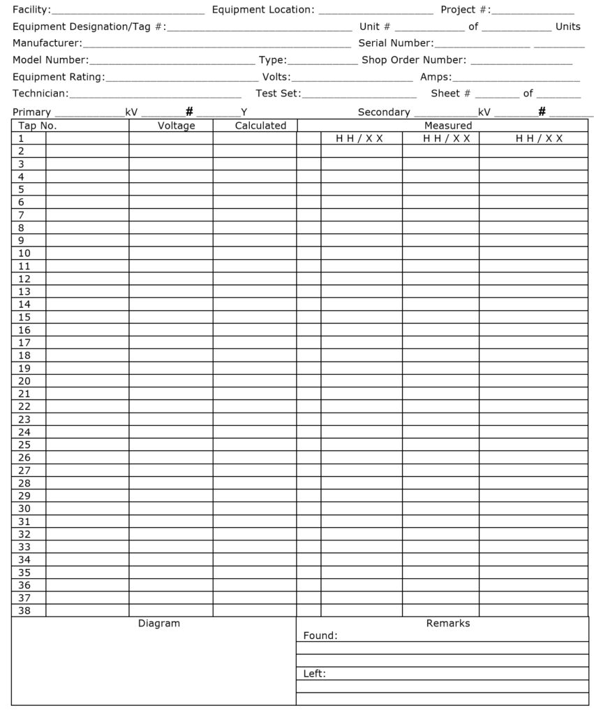
Transformer Turns Ratio Test Report
Transformer Insulation Power Factor Test Report
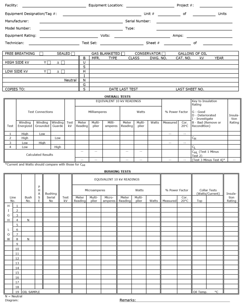
Transformer Insulation Power Factor Test Report – Excitation-Current Tests

Autotransformer Test and Inspection Report
5.1 Liquid-Filled Transformers Nameplate Data
Date:________
Facility:_____________ Equipment Location:______________________ Project #: __________
Equipment Designation:______________________________ Unit # _______ of ______ Units
Manufacturer:_________________________ Serial Number:________________________
Model Number:______________ Type:________ Shop Order Number: ____________________
Equipment Rating:____________________ Volts:________________ Amps:_____________
Related Articles:
- Sweep Frequency Response Analysis Testing
- Electrical Safe Work Practices
- Electrical Equipment Commissioning
- Commissioning: Substations and Outdoor Bus Structures
- Electrical Work
- Electrical Safety Awareness and Aptitude Training