This technical specification and method statement outline the necessary electrical work practices for the proper commissioning and maintenance of rotating equipment, specifically motors exceeding 600 hp. It’s important to note that this article does not serve as a definitive work scope or restrict the extent of work essential for the operation of such equipment.
Furthermore, this technical specification and method statement encompass visual and mechanical inspections, as well as electrical and functional testing procedures, specifically tailored for rotating equipment in the category of motors greater than 600 hp. These guidelines aim to ensure the effective and safe operation of such equipment within the designated parameters.
Electrical Motors Commissioning and Checklist
Motors Greater Than 600 hp Nameplate Data
Date:___________
Facility:_____________ Equipment Location:_______________ Project #: ____________
Equipment Designation:______________________ Unit # _______ of _______ Units
Manufacturer:___________________ Serial number:______________________________
Model number:____________ Type:___________ Shop Order number: _________________
Equipment Rating:__________________ Volts:_______________ Amps:______________
Technician:_________________________________ Sheet # ____ of ____
Visual and Mechanical Inspection for Synchronous Motors and Induction Motors 2250 hp and Above:
Upon the receipt of the equipment, a thorough inspection is essential to identify any physical damage that may have occurred during shipping. Any such incidents should be reported following the shipper’s instructions. Subsequently, the following steps must be executed:
- Connect stator heaters for optimal performance.
- Perform a load check, recording the amperage reading as required.
It is imperative to ensure the alignment of equipment nameplate information with the latest single-line diagram and equipment specifications. Additional key inspection points include:
- Verification of motor rating with the single-line diagram.
- Examination for loose fan blades, support bolts, shrouds, debris, drilling chips, shipping blocks, and the overall condition of windings, bracing, leads, and internal motor auxiliary devices and instruments.
- Evaluation of motor cover dust seal clearances on both the motor and exciter, where applicable.
- Measurement of air gaps on the exciter and motors with pedestal bearings, where applicable, with results meticulously recorded.
Further checks involve:
- Verifying the pressure of the flood lube system feed and drain, checking for proper flow, and detecting any leaks when the oil system is initially activated or during motor accessibility for other assessments. Attention must be given to correct inlet and outlet piping connections and the installation of a drain line sight glass, ensuring proper slope.
- Inspection for cooler leaks, with particular attention to internal piping connections where applicable.
- Conducting continuity and terminal marking tests of motor coil groups using a volt-ohm meter.
- Confirming the installation of proper crimp lugs on all connections, adhering to standards outlined in Medium Voltage Cable Testing and Installation.
- Performing wire checks on all C.T. circuits within the motor terminal box, with the use of ring-type lugs.
- Ensuring that the Micarta cable support piece in the motor terminal box is appropriately drilled and split to facilitate cable growth and removal.
- Validating connections of the ground loop across the entire motor and compressor system, shown in following diagram.
- Checking and recording collector slip ring run-out and brush spring tension where applicable.
- Verifying the tightness of accessible bolted bus joints, using a calibrated torque wrench method, and adhering to manufacturer’s instructions or, if unavailable, the table in Electrical Equipment Commissioning.
These meticulous inspections and checks are fundamental to ensuring the reliable and safe operation of synchronous motors and induction motors, particularly those with a capacity of 2250 hp and above.
Operational and Electrical Testing for All Synchronous Motors and Induction Motors 2250 hp and Above:
Here’s an overview of the operational and electrical testing procedures for synchronous motors and induction motors rated at 2250 hp and above:
- Check Bearing Insulation Resistance:
- This task is conducted before coupling and while the motor covers are removed.
- Ensure all piping and electrical connections to the bearing are included in the test.
- Record the results of the insulation resistance test for bearing insulation.
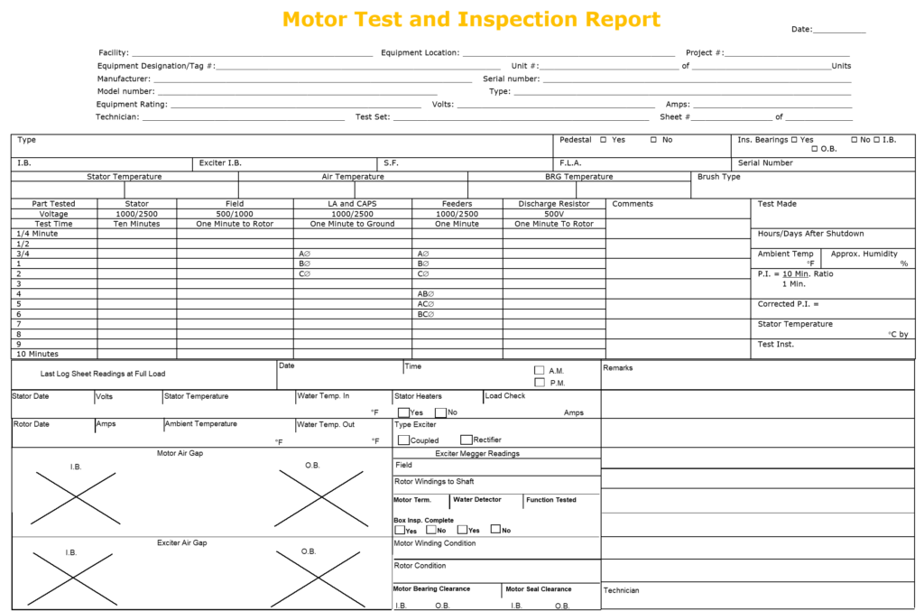
- Insulation Resistance (Megger) Test – Motor Stator:
- Utilize the polarization index for this test.
- Record the results of the insulation resistance test for the motor stator.
- Insulation Resistance (Megger) Test – Motor Feeders, Lightning Arrestors, and Capacitors:
- Conduct insulation resistance testing for motor feeders, lightning arrestors, and capacitors.
- Record the results of these tests.
- Insulation Resistance (Megger) Test – Motor Field Discharge Resistor, Exciter Stator, and Exciter Rotor (If Applicable):
- For motors equipped with field discharge resistors, exciter stators, and exciter rotors, perform insulation resistance tests.
- Caution: Isolate semiconductor devices before testing motor field discharge resistor and rotor, referring to the manufacturer’s instruction literature.
- Record the results of these tests.
- Check for Grounds in Static Devices, Terminals, Connections, and Control Wheel:
- Use a volt-ohm meter to ensure that no grounds exist in static devices, terminals, connections, and control wheel.
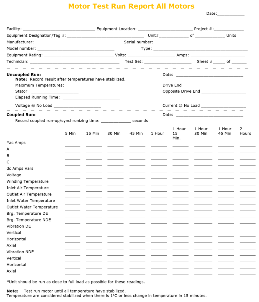
- Test Run – Uncoupled:
- Before coupling, initiate a test run of the motor to check for proper rotation.
- Caution: For flood or pressure lubricated bearing systems, ensure they are commissioned before motor starting.
- During the uncoupled test run:
- Record bearing temperatures and vibration levels.
- Run until temperatures have stabilized (considered stabilized when there is a 1 degree C change or less in 15 minutes).
- Listen for unusual noises.
- Record the results of this test.
- Test Run – Coupled:
- After the uncoupled test run and coupling, conduct a test run of the motor while it is coupled to the load.
- During the coupled test run:
- Record bearing temperatures and vibration levels.
- Run until motor temperatures have stabilized (considered stabilized when there is a 1 degree C change or less in 15 minutes).
- After stator temperatures have stabilized, verify the hottest RTD (Resistance Temperature Detector) and ensure it is in the shutdown circuit if applicable.
- Record the results of this test.
- Verify Out-of-Step Protection System:
- Confirm that the out-of-step protection system functions correctly to trip the breaker if applicable.
- Verify Bearing Grounding:
- Ensure that the non-drive end (NDE) bearing is ungrounded, while the drive end (DE) bearing is grounded.
These comprehensive testing procedures help ensure the proper operation and reliability of synchronous and induction motors rated at 2250 hp and above. It is essential to follow these steps meticulously to maintain the safety and efficiency of these critical components.
Visual and Mechanical Testing for All Induction Motors – 600 Through 2000 hp
Here’s a breakdown of the visual and mechanical testing procedures for induction motors ranging from 600 to 2000 hp:
- Inspect for Shipping Damage:
- Upon receiving the equipment, carefully inspect it for any physical damage that may have occurred during shipping.
- Report any incidents or damages as instructed by the supplier.
- Connect Stator Heaters:
- Ensure that the stator heaters are properly connected and in working condition.
- Perform a load check, recording the amperage: [Specify amperage value].
- Compare Equipment Information:
- Cross-reference the equipment’s nameplate information with the latest single-line diagram and equipment specifications to ensure alignment and accuracy.
- Check Continuity and Terminal Markings:
- Verify the continuity and terminal markings of motor coil groups. This can be done by opening the neutral connection and using a volt-ohm meter where applicable.
- Verify Proper Crimp Lugs:
- Confirm that the correct crimp lugs, as specified in Medium Voltage Cable Installation and testing, have been installed on all connections.
- Ensure that the use of test slugs complies with go/no-go standards.
- Wire Check for Current Transformer (C.T.) Circuits:
- Examine all current transformer (C.T.) circuits in the motor terminal box.
- Ensure that ring-type lugs are utilized where applicable for secure connections.
- Inspect Micarta Cable Support Piece:
- Check that the Micarta cable support piece in the motor terminal box is properly drilled and split.
- This facilitates cable growth and allows for cable removal as needed.
- Verify Group Loop Connections:
- Confirm the connections of the group loop throughout the entire motor and compressor system.
These procedures are essential to ensure the proper installation, condition, and connection of induction motors within the specified range. Following these steps meticulously helps maintain the reliability and performance of these motors in industrial applications.
Operational and Electrical Testing for All Induction Motors – 600 through 2000 hp
Here’s a breakdown of the operational and electrical testing procedures for induction motors ranging from 600 to 2000 hp:
- Check Bearing Insulation Resistance:
- Before coupling and with the motor covers removed, check the insulation resistance of the motor’s bearings.
- Ensure that all piping and electrical connections to the bearing are included in the test.
- Record the results of this test.
- Insulation Resistance Test – Stator:
- Perform an insulation resistance test on the motor stator using the polarization index method.
- Record the results of this test.
- Insulation Resistance Test – Motor Feeders, Lightning Arrestors, and Capacitors:
- Conduct insulation resistance tests on motor feeders, lightning arrestors, and capacitors.
- Record the results of these tests.
- Test Run – Uncoupled:
- Run the motor uncoupled and check for the proper operation of oil rings.
- Record the bearing temperatures and vibration levels.
- Continue running the motor until temperatures stabilize. Stability is reached when there is a change of 1 degree Celsius or less in 15 minutes.
- Listen for any unusual noises and record the results.
- Test Run – Coupled:
- Record bearing temperatures and vibration levels when the motor is coupled to the load.
- Run the motor until temperatures have stabilized.
- After the stator temperatures have stabilized, verify the hottest Resistance Temperature Detector (RTD) and ensure that it is integrated into the shutdown circuit where applicable.
- Similar to the uncoupled test, temperatures are considered stabilized when there is a change of 1 degree Celsius or less in 15 minutes.
Following these testing procedures diligently helps ensure the reliability and performance of induction motors within the specified power range (600 to 2000 hp) in various industrial applications.