SAES-L-133, along with similar standards and guidelines, provides essential measures for controlling internal and external corrosion as well as environmental cracking in a wide range of oil and gas facilities, including pipelines, structures, plant equipment, and more. These corrosion control measures are not limited to a specific phase but are intended to be implemented throughout the entire lifecycle of these facilities, from design and construction to operation, maintenance, and repair.
![Corrosion Protection Requirements for Pipelines, Process Equipment SAES-L-133 [PDF]](https://paktechpoint.com/wp-content/uploads/2023/08/Corrosion-Protection-Requirements-for-Pipelines-Process-Equipment-SAES-L-133-PDF-1024x576.png)
The standard likely outlines various strategies and techniques for corrosion control, including the selection of materials resistant to corrosion, protective coatings, cathodic protection systems, and monitoring and inspection protocols. Additionally, it may address specific environmental factors that contribute to corrosion, such as the presence of hydrogen sulfide (H2S) or other corrosive substances in oil and gas streams.
Overall, SAES-L-133 plays a critical role in ensuring the integrity and safety of oil and gas infrastructure by mitigating the risks associated with corrosion-related failures.
SAES-L-133Corrosion Protection Requirements for Pipelines, Process Equipment
Minimum Requirements for Corrosion Protection
5.1 Use of Corrosion-Control Measures:
This section states that the corrosion-control measures outlined in this standard must be applied to all piping and pressure-retaining equipment that is exposed either internally or externally to specific conditions mentioned in Sections 6.1, 6.2, or 6.3 of this standard. It is essential to consult SAES-L-132 for environment-specific materials selection and SAES-L-136 for specific restrictions related to carbon steel pipe types.
5.2 Non-Corrosion-Critical Piping Systems:
This part deals with piping systems that are not considered corrosion-critical. For these systems, you should follow the requirements outlined in relevant industry standards and codes. It’s important to note that some piping systems, even if not defined as corrosion-critical in this standard, may still require the use of corrosion-resistant materials as specified in other standards or codes. Examples of such systems include sewer lines, wastewater disposal lines, and potable water lines.
5.3 Conditions and Corrosion Control Methods:
In this section, there are two main categories of conditions: “Normal, Foreseeable, and Contingent Conditions.”
5.3.1 Normal, Foreseeable, and Contingent Conditions:
- Normal Operating Conditions: These are the conditions during the typical operation of the system projected over its design life, which should be a minimum of 20 years.
- Process Start-Up: Consider conditions during the start-up of the system.
- End of Run Variations: This involves variations in conditions as the system is shut down.
- Foreseeable Intermittent or Occasional Operations: This includes operations like hydrostatic tests, steam cleaning, or situations where contaminants may be carried over from an upstream process (e.g., caustic from a stripper).
For each of these conditions, appropriate corrosion control methods and materials must be selected. Additionally, measures must be taken to prevent specific types of cracking, including sulfide stress cracking (SSC), stress corrosion cracking (SCC) like caustic cracking, SOHIC, and other rapid environmental cracking mechanisms.
5.3.2 Contingent Conditions:
Contingent conditions refer to scenarios that may be encountered during construction, start-up, shutdown, process upsets, or the failure of a single component. Again, it’s crucial to choose corrosion control methods and materials for these conditions and take measures to prevent SSC, SCC, caustic cracking, SOHIC, and other rapid environmental cracking mechanisms.
Contingency failure requirements might not require provisions for general corrosion, localized corrosion, or hydrogen-induced cracking if the exposure time is very limited. However, if these contingent conditions persist for an extended period, additional corrosion control measures should be implemented.
5.4 Situations Not Adequately Addressed:
In cases where specific situations are not adequately addressed by existing industry codes and standards, it is recommended to use the best corrosion and materials engineering practices that are commonly accepted in the oil and gas and refining industry. This ensures that the most appropriate and effective corrosion control methods are employed in unique or less common scenarios. Consultation with experts in corrosion technology and materials engineering is advisable in such cases to make informed decisions.
How to Determine Corrosive and Crack-Inducing Environments?
1. Corrosive Environments:
For design purposes, an environment is considered corrosive if it meets any of the following conditions:
- Acidic or Near-Neutral pH Water with High Oxygen: If the water phase has an acidic or near-neutral pH and contains more than 20 micrograms per liter (20 ppb) of oxygen, it is corrosive. This applies particularly to water exposed to the atmosphere, which tends to contain dissolved oxygen.
- Extremely Low pH: If the pH of the water phase is below 5.5, whether determined from available data or measured in the field immediately after collection, it’s considered corrosive.
- High Carbon Dioxide Pressure: A water-containing multiphase fluid with a carbon dioxide (CO2) partial pressure exceeding 206 kPa (30 psi) is corrosive. For systems with CO2 partial pressures between 20.6 kPa and 206 kPa (3 psi and 30 psi), the need for corrosion control measures depends on the expected corrosion rate.
- High Corrosion Rate: Any condition that would cause a metal penetration rate of 76 μm/yr (3.0 mpy) or more is considered corrosive. This penetration rate could result from various forms of corrosion, including uniform corrosion, localized corrosion, or pitting. Determining this service condition requires consultation with corrosion engineers.
- Buried or Immersed Piping: All soils and waters in which piping systems are buried or immersed are considered corrosive.
- Solids in Water: A water-containing fluid stream that carries solid particles, like scale or sand, which can settle and initiate corrosion damage, is considered corrosive.
- Bacteria-Induced Corrosion: If a water-containing fluid stream carries bacteria that can cause Microbiologically Influenced Corrosion (MIC), it is considered corrosive.
- Insulated and Fireproofed Systems: Systems that are insulated and fireproofed also fall under corrosive environments.
2. Crack-Inducing Environments:
Environments that can induce cracks in piping systems or process equipment require specific control measures when predicted to occur during the design life of the system. These conditions include:
- 6.2.1 Sour Environments: Piping systems or equipment exposed to sour environments as defined in ISO 15156 or NACE MR0103 require measures to control Sulfide Stress Cracking (SSC).
- 6.2.2 High Sulfide Content: Systems exposed to environments with more than 50 ppmw (parts per million by weight) total sulfide content in the aqueous phase must use HIC (Hydrogen Induced Cracking) resistant steel.
- 6.2.3 Mercury Content in Cryogenic Service: Aluminum heat exchangers should not be used in gas stream cryogenic service where the mercury content exceeds 10 ng/Nm³ (nanograms per normal cubic meter) to avoid Liquid Metal Embrittlement (LME).
- 6.2.4 Other Recognized Crack-Inducing Environments: Environments recognized by other standards or good engineering practice as potential environments for Stress Corrosion Cracking (SCC) also require control measures.
3. High Temperature and Refining Environments:
High-temperature refinery environments, as identified by Saudi Aramco Best Practices and various API standards and documents (e.g., API RP 571, API PUBL 932-A, API RP 932-B, API RP 939-C, API RP 941, and API RP 945), also require specific consideration and control measures due to their unique challenges and potential for corrosion and cracking.
Corrosion and Cracking Control Measures
1. Corrosion Control Requirements:
To mitigate internal corrosion in piping systems and equipment, the following corrosion control measures are specified:
- Average Metal Penetration Rate and Corrosion Allowance: Design piping systems or equipment with at least one acceptable measure of internal corrosion control to achieve an average metal penetration rate of less than 76 μm/yr (3.0 mpy) or use an adequate corrosion allowance (e.g., 1.6 mm up to 6.35 mm) to ensure the system functions as designed until planned replacement. The corrosion allowance must adhere to industry codes and Saudi Aramco Standards.
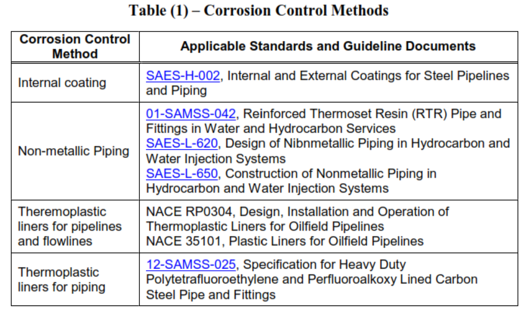
- Acceptable Corrosion Control Measures: Acceptable measures for corrosion control include:
- Corrosion-resistant alloys (e.g., austenitic and duplex stainless steel).
- Non-metallic materials and linings where permitted by Saudi Aramco standards.
- Coatings (internal/external) and linings (internal) meeting specific standards.
- Galvanic or impressed current cathodic protection.
- Chemical treatment, including the use of inhibitors and chemicals selected according to Saudi Aramco guidelines.
- First Fill Chemicals: For the initial filling of chemicals used for corrosion control:
- LSTK (Lump Sum Turnkey) contractors fund the purchase and ensure cleanliness and mechanical operation.
- Follow requirements for oilfield chemicals and water treatment chemicals as per Materials Service Group (MSG) standards defined in SAES-A-205, SAES-A-208, and specific contracts.
- Protection Against Soil-Side Corrosion: Protect all buried steel piping against soil-side corrosion with both external coating and cathodic protection. Use specified coating systems and install cathodic protection systems while evaluating and mitigating the risks of stray current corrosion.
- Offshore Pipeline and Platform Protection: For offshore pipelines and platforms, protect all submerged external surfaces with coatings specified in SAES-H-001 and SAES-H-004 and use cathodic protection as per SAES-X-300. Casings for offshore wells in nonelectrified fields must be externally coated.
- Protection of Offshore Structures: Externally protect offshore structures, piping, and other equipment exposed to the marine environment. Critical components should be sheathed with Monel through the splash zones, while other components exposed to the atmosphere or submerged in the splash zone should be protected with coatings specified in SAES-H-001, SAES-H-002, and SAES-H-004.
- Erosion Corrosion Prevention: Mitigate erosion corrosion by adhering to material selection and fluid velocity limitations as specified in SAES-L-132. Similar principles can be applied to cases not specifically addressed in SAES-L-132.
- 7.1.8 Microbiologically Influenced Corrosion (MIC) Mitigation: Mitigate MIC by controlling bacteria through the application of biocides, selecting resistant materials, and choosing appropriate coatings.
- 7.1.9 Protection of Low Flow and Stagnant Conditions: Piping and pipelines subject to low flow, intermittent flow, or stagnant conditions should be protected using internal coating, non-metallic piping, corrosion-resistant alloys (cladding, weld-overlay, thermal spray, or solid), or non-metallic liners. This includes specific components like flowlines, pipeline jump-overs, and production headers. Dead-legs are handled according to SAES-L-310, Paragraph 11.4. Reference standards and documents are provided for guidance.
These measures are essential for controlling and mitigating corrosion in various types of equipment and piping systems to ensure their integrity and longevity.
We outline following various corrosion control measures and guidelines for preventing corrosion in industrial systems, particularly in the oil and gas facilities. Here’s an explanation of the key points mentioned:
- Galvanic Corrosion Prevention: Galvanic corrosion occurs when two dissimilar metals come into contact in the presence of an electrolyte, leading to accelerated corrosion of one of the metals. To prevent this, insulating gaskets, insulated bolt sets, and insulating unions are recommended when dealing with highly conductive, corrosive fluids containing water.
- Exceptions to Insulating Devices: Insulating devices are not required for services that are dry or non-conductive. They are also generally not used in hydrocarbon service unless explicitly approved.
- Temperature Limitation on Insulating Gaskets: Insulating gaskets should not be used at operating temperatures of 250°F (121°C) and higher.
- Stainless Steel in Tempered Water: It is acceptable to use stainless steel instrument connections with carbon steel pipework in tempered water service.
- Use of Corrosion Inhibitors: Corrosion inhibitors can help reduce galvanic corrosion, but higher concentrations are needed to counteract this type of corrosion.
- Galvanic Isolation with Titanium: Galvanic isolation may be required when using titanium alloys to prevent damage mechanisms like hydriding. Consult the relevant department when using titanium alloys.
- Impact of Insulating Devices on Cathodic Protection: Installing insulating devices for galvanic isolation can affect the continuity of cathodic protection on buried pipelines and equipment. This impact should be evaluated during the design phase.
- Corrosion Prevention Under Insulation: Corrosion under insulation is a common issue. To prevent it, coating systems and wraps specifically qualified for this purpose should be applied to thermally insulated systems. Effective sealing and the use of non-absorbent insulation media are recommended.
- Corrosion Prevention Under Fireproofing: Corrosion under fireproofing is addressed by applying compatible corrosion-resistant coatings underneath fireproofing materials. Adequate sealing and precautions against water ingress are crucial.
- Corrosion During and After Hydrotest: Corrosion protection requirements for hydrostatic testing and post-hydrotest lay-up procedures are mandated, especially for stainless steel and copper alloy systems.
- Corrosion During Lay-up and Mothballing: Corrosion during short lay-up periods can be prevented with proper measures. Adequate planning and funding for mothballing are essential to maintain equipment readiness.
- Cracking Control Measures: This section emphasizes using materials that comply with specific standards and requirements to control various types of cracking, including SSC (Sulfide Stress Cracking), HIC (Hydrogen Induced Cracking), and SCC (Stress Corrosion Cracking). Different types of steel and coatings are prescribed based on the environment and application.
- High-Temperature Damage Mechanism Prevention: To minimize the risk of high-temperature damage mechanisms, including hydrogen attack, specific industry standards and best practices like API RP 941 and Nelson Curves are recommended. Water wash systems are also suggested to control high-temperature corrosion.
These guidelines are essential for maintaining the integrity and safety of equipment and systems in industries prone to corrosion, such as the oil and gas sector. They aim to prevent costly failures and ensure the long-term reliability of infrastructure.
International Codes and Standards used for this Article:
American Petroleum Institute
API RP 571 – Damage Mechanisms Affecting Fixed Equipment in the Refining Industry.
API RP 578 – Material Verification Program for New and Existing Alloy Piping Systems.
API RP 579-1/ASME FFS-1 Fitness-for-Service.
API RP 580 – Risk Based Inspection.
API RP 581 – Risk-Based Inspection Technology.
API RP 584 – Integrity Operating Window.
API PUBL 932-A – A Study of Corrosion in Hydroprocess Reactor Effluent Air Cooler Systems.
API RP 932-B – Design, Materials, Fabrication, Operation, and Inspection Guidelines for Corrosion Control in Hydroprocessing Reactor Effluent Air Cooler (REAC) Systems.
API RP 934-A – Materials and Fabrication of 2¼Cr-1Mo, 2¼Cr1Mo-¼V, 3Cr-1Mo,
and 3Cr-1Mo-¼V Steel Heavy Wall Pressure Vessels for High temperature, High-pressure Hydrogen Service.
API RP 934-C – Materials and Fabrication of 1 1/4Cr-1/2Mo Steel Heavy Wall Pressure Vessels for High-pressure Hydrogen Service Operating at or Below 825°F (441°C).
API RP 939-C – Guidelines for Avoiding Sulfidation (Sulfidic) Corrosion Failures in Oil Refineries
API RP 941 – Steels for Hydrogen Service at Elevated Temperatures and Pressures in Petroleum
Refineries and Petrochemical Plants.
API RP 945 – Avoiding Environmental Cracking in Amine Units.
American Society for Testing and Materials
ASTM C795 – Standard Specification for Thermal Insulation for Use in Contact with Austenitic Stainless Steel Energy Institute
Guidance for Corrosion Management in Oil and Gas Production and Processing, May 2008
European Federation of Corrosion
EFC 55 – Corrosion under Insulation Guidelines
The International Society of Automation (ISA)
ISA 71.04 – Environmental Conditions for Process Measurements and Control Systems: Airborne
Contaminants.
International Organization for Standardization
ISO 15156/NACE MR0175 Petroleum and Natural Gas Industries – Materials for Use in H2S-Containing Environments in Oil and Gas Production.
ISO 14224 – Petroleum, Petrochemical, and Natural Gas Industries – Collection and Exchange of
Reliability and Maintenance Data for Equipment
Manufacturers Standardization Society
MSS SP-54 – Quality Standard for Steel Castings for Valves, Flanges, and Fittings and Other Piping Components – Radiographic Examination Method.
National Association of Corrosion Engineers
Commentary Note:
NACE is in the process of changing the designations RP to SP. Use the equivalent SP document when it is issued.
NACE MR0103 – Materials Resistant to Sulfide Stress Cracking in Corrosive Refinery Environments.
NACE SP0198 – Control of Corrosion under Thermal Insulation and Fireproofing Materials
NACE SP0102 – In-Line Inspection of Pipelines.
NACE RP0170 – Protection of Austenitic Stainless Steels and other Austenitic Alloys from Polythionic Acid Stress Corrosion Cracking during Shutdown of Refinery Equipment
NACE SP0403 – Avoiding Caustic Stress Corrosion Cracking of Carbon Steel Refinery Equipment and Piping.
NACE SP0407 – Format, Content, and Guidelines for Developing a Material Selection Diagram.
NACE Report 34101 – Refinery Injection and Process Mixing Points
NACE Report 34103 – Overview of Sulfidic Corrosion in Petroleum Refining