General Preparatory works for pipework erection. First Confirm the turnover of civil works foundation/pedestals form for the installation of pipe racks. Secure necessary work permit from Contractor Representative prior to start of work/activity.
Check foundations and other connection points to confirm locations, orientation
elevation and condition. Identify the structure members for leave-out (if any) due to installation of equipment and other pre-requisite.
Prior to turnover, ensure that the completed foundation with anchor bolts was already checked and its dimensions, levelness, alignment, top of concrete elevation, surface finish, and others are as per the latest revision of drawings and within acceptable tolerances.

Industry Codes and Standards for Structural Work
AISC AISC Code of Standard Practice, Specification for Structural Joints Using ASTM A325 or A490 Bolts.
AWS 01 .1 Structural Welding Code.
PIP STS05130 Erection of Structural and Miscellaneous Steel Specification.
Erection Of Piperack Procedure | Method Statement
Anchor Bolt Setting for Piperack Erection
- Anchor bolts shall be installed as shown on the design drawings.
- Installation Contractor to coordinate with other trades when inserts placed by others are required.
- Installation Contractor to fill voids in sleeves with readily removable material to prevent the entry of concrete, dirt, etc.
- Anchor bolts shall be positioned and secured within the tolerances as per design drawings.
- Wooden templates shall be used to securely position all column anchor bolts. Templates shall be supported independent from the reinforcing steel.
- Unless shown otherwise, anchor bolts shall be set perpendicular to the theoretical
bearing surface. - Anchor bolts shall be securely held in position and shall be checked immediately after the concrete is placed.
- After the concrete has hardened sufficiently, the exposed portion of anchor bolts shall be cleaned of all concrete and the thread chased. Threads shall be carefully coated with grease and the washers and nuts installed.
- Anchor bolts shall be protected with plastic wrap on its thread before pouring.

Installation and Grouting of Packer Plates
- Clean the top of bearing surfaces and bottom of base plates. Set and shim column base plates to correct positions, elevations, and locations as shown on the latest approved erection drawings. Shims and wedges to be used shall be provided by Contractor, setting nuts shall be loosened before grouting as per PIP STS05130 6.4.1.
- Ensure that the top of foundations have been properly roughened for bonding Laitance, oil, grease, dust, sand and other foreign matter shall be removed if any.
- Dry Pack Grouting;
Contractor shall conduct one (1) time sampling/testing for dry pack grouting during setting of packer plates to ensure compressive strength of grout materials conforms to requirements.
Mixture of grout to be used for installation of packer plates shall be dry pack “non-shrink cementitious grout” in accordance with manufacturer’s recommendations.
Sampling, curing and testing grout specimen shall follow procedure as specified in Method Statement for Non-shrink Grout Installation.
- Setting of packer plates or other adjusting devices shall be in a manner that will ensure structural members are located in correct positrons and elevations.
- Install packer plates (100 x 100 x 5mm thk.) in location(s) as applicable in-between anchor bolts of concrete pedestal. Packer plates will be coated as pet applicable coating system schedule. Grade of packer plate shall be ASTM A36/ASTM A36M as per 12-SAMSS-007 sec. 4.2.
- Conduct inspection for elevation and location of installed packer plates.
- Upon acceptance and curing of dry pack grout installation and packer plates setting, erection of pipe rack shall commence.
Preassembly and Erection
- All materials shall be place on designated area near the location for assembly and erection.
- Surface of steel structural member shall be clean by air blowing on ground prior for lifting work.
- Provide dunnage underneath to avoid materials on direct contact with soil and protect from dirt.
- After pre-assembly check if the bolt is already at snug tight condition by using a test hammer. Mark the bolt as applicable.
- Lifting of painted structural shall be done with non abrasive choker.
- The crane responsible for loading or unloading structural members shall be assigned separately prior to erection works.
- Position the cranes(s) on designated area. Crane #1 (55T minimum) shall be responsible for the pre-assembly of column and girders in ground level and assisting crane #2 for erecting frame assembly. Crane #2 (90T minimum) shall be responsible for the erection of frame assembly from ground level to its designated location and assisting erection of girders connecting frames. Crane #3 (30T minimum shall be responsible for the erection of girders connection to erected frames, tie beams and bracings. The ground where the crane(s) will be position shall be stabilized. Clearance for the crane access way shall establish and maintained in the duration of works.
Pre-alignment of structure
After completion of steel erection, plumbness checking and alignment of erected structure shall commence form Grid lines until the alignment and plumbness of all columns have been checked and corrected. QC inspection shall follow to verify alignment and plumbness records as per TIP. Plumbness/alignment checking and correction works shall progress continuously after erection of structure until it reaches.
Alignment inspection for completed steel structure shall be done prior to welding and final bolting tightening; steel structure shall be totally inspected for accuracy of construction and to ensure that all dimensions are as specified.
Bolt Tightening
After QC inspection and acceptance of pre-alignment records, bolt tightening shall be done at all Grid lines of Pipe rack. Refer to (Detailed Procedure on Bolt Tightening).
Platforms and Access-ways assembly and installations
Platforms and access-ways on pipe rack shall be installed after the structure is fully erected. Refer to “Erection of Platform and Access Way” for detailed procedure.
Detailed Procedure on Bolt Tightening
Bolts Connections / General Requirements
- ASTM A325M bolts shall not be reused. Where ASTM A307 bolt assemblies are used for connecting miscellaneous items (i.e., handrail assemblies, pipe supports, gates, etc.) to structural members, the bolts shall be tightened to snug tight condition.
- Installation Contractor shall color code the ends of the tightened bolts by placing a yellow paint mark indicating that the bolts have been properly tensioned and are ready for inspection.
- Enlargement of bolt holes for the correction of misalignment shall be by reaming or drilling only. Flame cutting, burning shall subject to approval.
- The mill certificates for the faster materials shall meet ASTM specification.
- Prior to commence work, impact wrench shall be properly calibrated to desired tension using bolt tension calibrator.
- Calibration of bolt tension calibrator shall be in every six (6) months or stringent requirements.
Bolt Tightening Condition
Tightening condition shall be in accordance with sec. 4.4 and 4.5 as noted in the standard drawings. Bolt applicable for the bolt tightening procedure shall be ASTM A325M for M20, M24 and M30.
This tightening method should be applicable for the various types of structures connection details as specified in the drawings, and various structure IFC drawings and various structure IFC drawings as indicated as the following abbreviation.
Type of connection for Snug Tight condition
• S*(** such as L, S, R, RL), CS, CSF, LT, HY, L TE, HYE, HYI, H, K, V, EJ, IJ; Structure member (e.g. UB254x31-SL).
• No additional or excess tightening force shall be applied to the bolts where snug tight condition has been confirmed.
Type of connection for Fully Tightening Condition
• This tightening method should be applicable for the various types of structure connection details as specified in the drawings and various structure IFC drawings as indicated as following abbreviations.
• EM** (** such as EMTB, EMBH); Structure member (e.g. UB610x140- EMB).
Bolt Tightening Methods:
Snug Tight Procedure
- Check the fastener assemblies (bolt, washer and nut) combination, diameter, length and grade to be used in the connection of joints.
- Aligned all bolt holes for the insertion of bolts to avoid damage on the threads.
- Placed bolts in all holes with washers positioned and nuts threaded to complete assembly by finger tight.
- By using ordinary spud or manual wrench, the ironworker shall equally tighten the bolts and nuts until the connected piles are in firm contact, but not necessarily continuous contact.
- There must be no gaps between the layers of steel where bolt penetrate the steel, these gaps must be away from the bolt holes, 25mm minimum contact around hole, but not less than the bolt diameter.
- Tightening shall be progress systematically from the rigid part of joint to its free edges. Secure loosen bolt among bolt assembly.
- Re-tightening of bolts as per above procedures shall not be considered as a reuse.
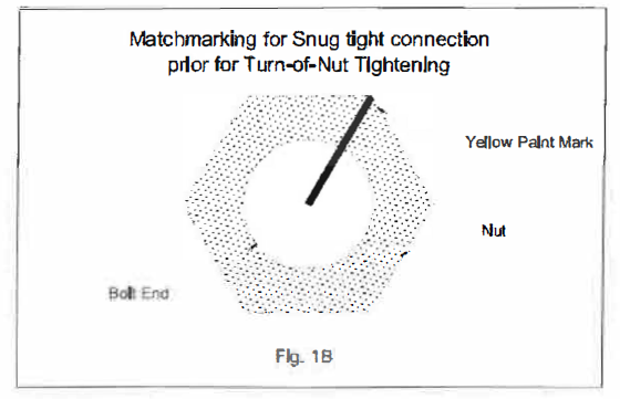
- To confirm whether the bolt connection is in snug tight condition, the protruding end of the bolt and nut shall be marked by yellow paint as shown in Fig. 1A and Fig. 1 B to indicate that the bolts have been properly tightened after inspection by test hammer.
- For S* (** such as L, S, R, RL), CS, CSF, LT, HY, LTE, HYE, HYI, H, K, V, EJ, lJ; Structure member (e.g. UB254x31-SL).

- For EM** (**such as EMTB, EMBH); Structure member (e.g. UB61 Qx 140-EMB).
- In case snug tightening shall be done using impact wrench, the following procedure specified in para. “Pretensionning Procedure Verification Testing” shall be done prior for commencement of the work.
- Tighten the nut to the value pre-set to impact wrench.
- Confirm match-matched connection following procedure in Fig. 1 B.
Fully Tightening by “Turn of Nut” Method
Prior to the application of Turn of Nut pre-tensioning, the bolted joint assembly shall be in snug tight condition.
After all bolts are in snug tight condition and match-marked, the nut or bolt head is rotated to the amounts of turn specified in Table A (refer to attachment B).
Rotation of the nut or head is applied to all fastener assemblies in the joint, progressing systematically from the most rigid part of the joint in a manner that will minimize relaxation of previously pre-tensioned bolts.
To confirm if the bolt is in Turn-of-Nut condition and properly tensioned, see Fig. 2 as illustrated.

Pretensionning Procedure Verification Testing
- Prior to installation of fastener assembly, confirm if the tension calibrator is properly calibrated, pretensionning demonstration shall be conducted to confirm the sequence of work.
- Take three (3) representative samples of complete fastener assemblies (bolt, nut and washer) of each combination of diameter, length, and grade and lot to be used in testing activity.
- Assemble the first set of bolt, washer and nut combination into a tension calibrator, and then tighten the bolt on snug tight condition. Match mark the bolts and nuts as shown in Fig. 1 B.
- Snug tight is defined as the tightness that exists when the plies of the joint are in firm contact. This may be attained by a few impacts of an impact wrench or the full effort of a man using as ordinary spud wrench.
- Following this initial operation, bolts in the connection shall be tightened further by the applicable amount of rotation specified in Table A (refer to attachment B).
- The test shall be verified that the pretensionning method develop a pretension that is equal to or greater than 1.05 times the tension required by Table B (refer to attachment B).
- Remove the assembly and repeat the procedure until all three {3) samples have been tested.
- Verification and inspection shall be conducted in accordance with SATR-M- 2002 to M20, M24 and M30 bolts.
- Visual inspection after pretensionning is required to ensure that fastener assemblies are matched-mark as illustrated to Fig. 2.
- A calibrated tension calibrator shall be onsite when tightening is to be performed on pre-tensioned joints.
Final Alignment
Prior for final grouting, final alignment inspection shall commence to ensure structure plumbness following the tolerances specified in Appendix I “Erection Tolerances” on JGC Specs, unless otherwise specified on design drawings and/or erection plans.
Conduct final alignment inspection using International Standards.
Final Grouting
Subsequently the erection and final alignment of structures is done, final grouting of
packer plates shall commence to complete the erection works. Installation, curing, and
inspection as specified in para. above.
Welding works
Whenever that field welding is required, the welding for main steel members and important joints of steel structures shall be performed in accordance with AWS 01 .1.
Welders shall have valid qualifications which have been certified by means of Job Clearance Card as per Performance Qualification Testing of Contract Welders and Brazers SAEP-323 & Certification Review and Registration of Project Welders SAEP-324.
Welding equipment to be used shall be properly calibrated prior to use at site. Welding equipment shall always be electrically grounded when in use.
Touch-up Application
As mentioned in Specs., when damaged painting or galvanized surface on surface on
steel structure is observed, and the unpainted area by masking at connection is
exposed, surface shall be touch-up.
All repaired, reworked, damage galvanized steel supports and gratings will be
coated as per applicable coating system schedule.
Tools & Equipment used in Piperack Works
Tools and equipment will consist but not limited as below:
- Mobile Crane 160 tons.
- Mobile Crane 55/70 tons.
- Crawler Crane 280 tons.
- Manlift.
- Trailer/tractor.
- Boom truck.
- Welding machine (calibrated).
- Air compressor.
- Tower lights.
- Manbasket.
- Impact tools.
- Magnetic drill.
- Surveying Instrument (calibrated).
- Rigging Tackles.
- Guy wires/ turnbuckles/ chain blocks.
Note: Tools and equipment should be in good condition and must be checked by competent
person and respective supervisor prior to use in the plant. Third Party vehicle and equipment
inspections and vehicle stickers required. Saudi Aramco certified where required.
Piperack Works Safety Precaution
- Approved work permit should be obtained prior to the start any structural works.
- Work execution shall be carried out in accordance with this method of statement.
- Erection crew must carry out a safety risk assessment prior to the start of any new activities.
- During any lifting works, signalman must be assigned full-time.
- The necessary manpower inclusive of supervisory staff, tools, equipment, materials, and other resources required must be made available and ready to use.
- Workers should wear their PPE’s needed for work.
- A Fire Watcher with fire distinguisher shall assign for any hot work activity.
- Certified permit receiver, firewatcher, traffic/flagman and work-in-charge should be at work site during the execution of the work.
- Use of special Manbasket (engineered lifts) is subjected for inspection prior to be utilized on steel erection works.
- Personnel who will be working from a suspended workbasket should secure Suspended
Personnel Work Basket Authorization/ Permit prior to start work. - Manbasket shall be inspected and be tagged with Saudi ARAMCO Certification.
- Manlift equipment shall be tested and certified by the Saudi ARAMCO Equipmen Inspection Division.
- Only certified manlift operator(s) shall be allowed to operate the manlift equipment.
- Sufficient lightings shall be provided if work is done at night time. Work at night shall be
approved by client. - Full body harness with double lanyards (inspected before use with details recorded) shall be at all times when working at elevated platforms 1.8 meters high and above.
- A ½” diameter wore rope must be provided for safety lifeline.
- Good housekeeping must be maintained in the duration of works.
- Supervisors/ Engineer shall monitor compliance of entire working crew to safety procedure until the work is fully completed.
- It shall make sure that the structural installation and erection of pipe rack shall be incident and injury free.
- The erection area shall blocked by physical barricade and warning taped during any lifting work to ensure safety.