This article provides minimum requirements for analyzing the flexibility of aboveground and underground piping systems. This article supplements the requirements of ASME B 31.3 code on flexibility, layout, supports, and anchoring of piping systems. It establishes a design basis for permissible piping loads on various equipment nozzles.
4 Piping Flexibility Analysis General
4.1 The use of expansion joints is subject to SABIC approval. The expansion joints shall conform to SES P01-E08.
4.2 Adequate and proper restraint should be provided to prevent flow induced vibration.
4.3 The use of cold spring shall is prohibited.
4.4 The requirements specified in PIP PNC00001, for Reciprocating compressor and pump’s piping, Spring Supports, Sway Braces, Sway Struts and hydraulic or mechanical snubbers shall be considered.
4.5 Flexibility requirement and stress analysis of power piping shall be as per ASME B31.1
4.6 Flexibility requirement and stress analysis of transportation pipelines shall be as per ASME
B31.4 & B31.8.
5 Piping Flexibility Analysis Parameters
5.1 Piping System
For the purpose of analysis, a piping system has to be defined properly. A piping system means the main piping (biggest size) along with its connected branch piping (if any). While defining the system, its associated supports, restraints, end connection should be properly considered. The piping system should be terminated up to the point where rigid restraint is available.
The end connection should be rigid type, i.e. preferably anchor, otherwise semi-anchor. In case the end connection has no anchor/ semi-anchor in reality, then the system is be extended up to the next anchor. Alternatively, to avoid the system becoming too large, a semi-anchor (directional stops) should be provided at the terminal point. As far as possible, anchor, only for sake of system isolation, should be avoided; as it is harmful to the system for thermal effect.
The connected branch piping (if any) reduces the flexibility of the piping. But its inclusion in the system increases the size of the system resulting in the difficulty of handling. The following should be considered for practical approach compromising these two divergent effects:
a. Small bore NPS 1.5 & below branch is excluded.
b. Branches having section modulus 10 percentage of main pipe and below is excluded. However, only the branch element should be included with its stress intensification factor (SIF).
c. Branches having section-modulus more than 10 percentage is to be included. The extent of such branch is up to a point where anchor/ semi-anchor/ or directional stops are there.
5.2 Installation Temperature
- Extreme installation temperature shall be taken into account in displacement stress range check.
- For cold service lines the extreme maximum ambient temperature shall be taken.
- For hot service lines the extreme minimum ambient temperature shall be taken.
- The minimum and maximum ambient temperature shall be obtained from project BEDD for various locations in Saudi Arabia.
5.3 Stress Range Calculation
For stress range calculation, whichever of the equations listed below produces the greatest temperature differential shall be used:
a. Pipe design temperature (Tp) shall be obtained from the Piping Line list.
b. The temperature difference ΔT to be considered in verifying flexibility, shall be determined as shown in Table-I.
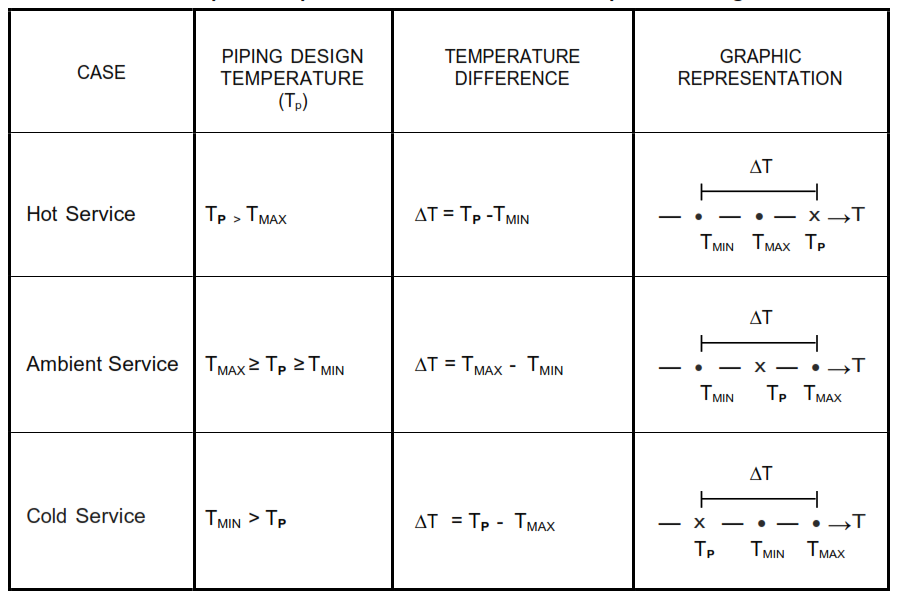
Where, T min = Extreme minimum ambient temperature
T max = Extreme maximum ambient temperature
5.4 Analysis Temperature
The flexibility analysis shall be carried out based on the temperature as below:
5.4.1 Use installation temperature for hot and cold service piping as explained under the heading ‘Installation temperature’.
5.4.2 The equipment design temperature and the line list design temperature shall be used to
verify the stresses in accordance with ANSI B31.3.
5.4.3 For rotating equipment and some of the static equipment ( like Air fin coolers, fired heaters), the equipment’s maximum temperature and line’s mechanical line list maximum operating temperature shall be used to evaluate movement, forces and moments on equipment’s nozzles and on line supports. Where necessary occasional loads and hydraulic test condition shall be considered to evaluate movement, forces and moments on nozzles and supports. Conditions like start-up, shutdown, regeneration, depressurizing and other special conditions) should also be considered for system integrity check.
5.4.4 For static equipment like, vessels, drums, heat exchangers etc., the mechanical line list’s design temperature shall be used to evaluate movement, forces and moments on equipment’s nozzles and on line supports.
5.4.5 For any non-insulated piping with a design temperature below solar temperature and subject solar radiation heat gain, the metal temperature shall be solar temperature of the region.
5.4.6 Operating temperature of steam shall be considered for steam-out temperature.
5.4.7 Thermal displacement for equipment nozzles shall be calculated by using the operating temperature. Thermal displacement for equipment support (e.g. Skirt on columns) should be calculated considering average temperature. For bare support, the average temperature is the arithmetic average. For insulated case, the average temperature is the average considering 180oC temperature drops per meter or other equivalent approach.
5.4.8 Operating temperature shall be used for spring support design.
5.4.9 When pumps are arranged with one pump operating and another at stand-by, three different cases shall be considered: –
a. Both pumps operating
b. Pump A operating, Pump B stand-by.
c. Pump B operating, Pump A stand-by
5.4.10 When pumps are arranged with two pumps operating and another at stand-by, three different cases shall be considered: –
a. Pumps A & B operating, Pump C stand-by.
b. Pumps A & C operating, Pump B stand-by.
c. Pumps B & C operating, Pump A stand-by.
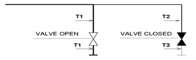
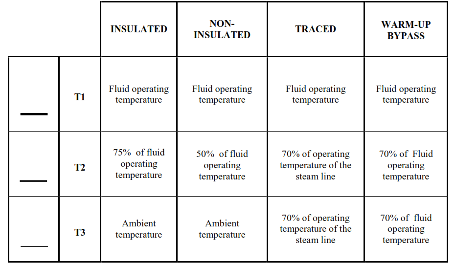
5.4.11 Lines that do not have flow, (such as branch piping connected to spare pumps), the
analysis temperature for that portion of line shall be as represented in figure.1 and Table – II.
5.5 Friction
5.5.1 Equipment nozzle loads, anchor and support loads shall consider the effect of friction. Friction effects shall never be used to reduce applied loads.
5.5.2 The value of coefficient of friction ( µ ) acting at pipe supports shall be in accordance with SES-B01-E01
5.5.3 PTFE may be used to reduce equipment loads to within the acceptable limits where no other logical piping routing can be achieved.
5.5.4 Frictionless unrestrained movement of the piping system shall be assumed only if the entire system is supported by means of rod or spring hangers.
5.6 Spring hangers
5.6.1 Spring hanger’s displacements shall be calculated in operating conditions and the characteristic (loads, spring rates, etc.) imposed in final calculations. Design Engineering Company to check that the spring shall be suitable for all severe and normal operating conditions. For proper determination of spring hanger loads, all weights of piping components including spring’s tie-rod, turn buckle and clamps shall be validated.
5.6.2 The load variation percentage shall not exceed 25 percentage. For piping connected to rotating equipment the load variation shall not exceed 10 percentage.
5.6.3 Horizontal movement of the attachment point of the pipe shall be taken into consideration and shall not cause an assembly rotation greater than 4°.
5.6.4 The spring travel shall be verified for all thermal condition.
5.7 Maximum Pipe Spans and Deflections
For determining pipe spans, the maximum sag / deflections shall be limited to 16 mm (5/8 in). This value does not apply to slope lines.
5.8 Water Hammer
5.8.1 Piping systems subject to water hammer shall be considered in stress analysis.
5.8.2 Forces due to water hammer shall be determined and suitable pipe restraints shall be provided.
5.9 Steam Out
The analysis shall consider whether the equipment and the piping are steamed out together or
separately. The allowable sustained stresses can be increased by a factor of 1.33.
5.10 Steam Tracing
Lines which are steam traced shall have an additional check to a temperature of 70 percentage
of the steam tracing temperature,
5.11 Differential Movement
5.11.1 Differential settlement of 20 mm for the compressor foundation shall be considered during the stress analysis of compressor piping.
5.11.2 Differential movements of equipment nozzles shall be considered in the Piping analysis as per Table IV.
5.12 Hydrotest
Hydrotest loads shall be calculated for pipes NPS 10 and larger.
5.13 Seismic Loads
5.13.1 Seismic analysis is to be considered as an occasional load case during stress analysis and it should not be combined with other occasional load cases such as wind loads.
5.13.2 Seismic load on piping system shall be determined in accordance with the procedure outlined in SES B01-E01.
5.13.3 The Spectrum method (quasi-static) is used for piping as per P01-E13, as it is preferred to equivalent static method because of non-linear/ distributed mass system of piping. However, Equivalent static method is also acceptable considering 100 percentage mass participation.
5.13.4 Piping stress analysis shall consider seismic load for line sizes NPS 6 and above.
5.14 Wind Loads
5.14.1 Wind Analysis is to be considered as an occasional load case during stress analysis and it should not be combined with other occasional load cases such as earth quake loading. Wind load on piping system shall be determined in accordance with the procedure outlined in SES B01-E01.
5.14.2 Equivalent static method is acceptable for stress analysis of wind loads.
5.14.3 A shape factor of 0.7 shall be applied to these loads to calculate the loads acting on the pipes.
5.14.4 Piping stress analysis shall consider wind load for line sizes NPS 12 and above (including insulation thickness). The elevation of piping shall be considered 10 m and above.
5.15 Snow Loads
Design for snow loads is not required for plants built in Kingdom of Saudi Arabia unless otherwise stated.
5.16 Impulse Loads
5.16.1 The significant loads caused by Water Hammer, Pressure Safety Valve, Rupture disc opening and Slug Flow shall be indicated as Impact force and shall be considered in the analysis with reference to P01-E11.
5.16.2 Piping systems subjected to impulse loads shall be designed to have a minimum natural frequency of 4 Hz.
5.16.3 Lines that are subject to slug flow shall be restrained where necessary.
5.16.4 An Anchor support shall be considered for safety valve piping. When two or more safety valves are in parallel, stress analysis shall consider the different operating conditions. All reaction forces during safety valve(s) blow-off shall be accounted in the piping stress analysis.
5.17 Two phase other lines
Piping system subjected to vibrations due to two-phase flow and similar flow regimes shall be designed for a minimum natural frequency of 4 HZ.
5.18 Jacketed Pipes
Two possible operating conditions shall be considered for stress analysis, which are:
a. The core fluid is hotter than the jacket fluid
b. The jacket fluid is hotter than the core fluid.
For both cases stress analysis shall consider the core fluid and the jacket fluid at their operating
temperatures. An additional shutdown calculation is required for case ‘b’ with both pipes at the
jacket fluid temperature.
5.19 Centrifugal Pump
5.19.1 The effect of spare pump piping shall be considered in the thermal analysis of all pump
piping systems
5.19.2 To minimize the damaging effects of water hammer and other impulse type loading on
pump nozzles, consideration shall be given to locating swing type check valves in discharge
lines in the vertical position above rigidly supported elbows so that hammer loads may be
distributed to grade or steel. For details of typical piping arrangement, refer SES G23-E02.
5.20 Steam Turbines
5.20.1 The dead weight of the piping shall be entirely supported by pipe hangers or supports.
5.20.2 Pressure safety valve discharge lines shall be supported in such a manner that the
relieving force during discharge does not impose loading in excess of the manufacturer’s
recommended allowable nozzle loading.
5.20.3 Turbine piping analysis shall include, as an additional case, bypass line hot with trip and
throttle valve closed. The equipment will be cold.
5.21 Centrifugal Compressors
5.21.1 Certified weights for valves and actuators shall be obtained from supplier. Weights for
insulation and cladding, pipe support attachments, flanges (including the piping flange
connected to the equipment) and bolts for flanges etc. shall be included.
5.21.2 The dead weight of the piping shall be entirely supported by pipe hangers or supports.
5.21.3 When spring selection has been made and all other restraint types and locations have
been determined a “nozzle released” calculation shall be run. This is to ensure that the nozzle
alignment falls within the agreed tolerances. For allowable tolerances refer to API RP-686.
5.21.4 The main restraints local to the compressor for protecting the nozzle, shall be designed
to enable site adjustment. Adjustable struts, which are frictionless, are the preferred method of
restraint.
5.22 Reciprocating Compressors
5.22.1 Piping systems shall be supported to ensure that their frequency is higher than the
critical frequency of compressor. This critical frequency shall be agreed with the equipment
manufacturer.
5.22.2 An acoustic simulation and mechanical response study shall be carried out by the
equipment manufacturer, in accordance with SES G13-S01, API 618 and API 688. Dynamic
analysis shall be carried out for reciprocating Compressors piping including analog study. The
natural frequency of the piping system shall be maintained above 7 Hz.
5.22.3 Pipe supports shall be located to avoid the natural frequency of piping spans by
anchoring where necessary and thereafter held down at frequent intervals. Supports shall be
located close to valves and changes of direction to reduce pulsation. Refer P01-E12 and API RP
686 and API 688 for further details.
5.22.4 Adjustable supports shall be provided for all pulsation dampeners not directly mounted
on top of compressor cylinders.
5.22.5 Hold down piping supports shall be designed and oriented so as to minimize thermally
induced forces and moments at pulsation dampener nozzles.
5.23 Reciprocating Pumps
5.23.1 The acoustic simulation and mechanical response study analysis shall be obtained from
equipment Manufacturer. Dynamic analysis shall be carried out on reciprocating pumps piping
including analog study. The natural frequency of the piping system shall be maintained above 7
Hz.
5.23.2 Suction and discharge piping to positive displacement reciprocating pumps shall contain
hold-down restraints on piping to minimize the potential of pulsation loading on pump nozzles
should pulsation dampeners become inoperative.
5.24 Fired Heaters
5.24.1 Pipe runs should be arranged perpendicular with the radiant tubes of the heater. This
allows the tubes to be used for piping flexibility as they are designed to move laterally up to 25
mm, but are not designed for any axial movement.
5.24.2 If the fired heater piping analysis incorporates the heater coil connections in the model,
the calculated displacements at the nozzle/ shell interface shall be submitted to the equipment
manufacturer for review and approval.
5.24.3 The effect of expansion and/or displacement of the tubes shall be reflected in the
computer analysis. Computer analysis of piping systems connected to floating heater coils shall
include the heater coil or an approximate model of the coil as part of the system and the effects
of internal guides and restraints. When heater coils are floating, the supports of the connecting
piping system shall be completely and independently balanced so that no dead load is imposed
on the coil.
5.25 Air Coolers
5.25.1 The header boxes for multiple bundled Air Coolers shall be supported on low friction
slide plates.
5.25.2 In general the inlet piping to multiple bundled Air Coolers shall be as rigid as possible
local to the header boxes.
5.25.3 The header box movement of a multiple bundled Air Cooler can be controlled in two
ways: –
a. One of the center header boxes is fixed to the support frame (preferred).
b. The inlet header pipe is anchored.
In either case, a suitable clearance shall be provided between the header boxes and the
supporting framework. It should be noted that the minimum clearance required by API 661 is
often insufficient. The Design Engineering Company shall need to confirm this requirement.
5.25.4 At “even-pass” units the outlet piping shall have sufficient flexibility to cater for the lateral
expansion of the air cooler bundles.
5.25.5 At “odd-pass” units the outlet piping shall allow for failure of a single fan. Temperature of
the outlet piping shall be assumed to be the same as the inlet piping. If this causes problems a
more accurate outlet temperature is to be obtained.
5.25.6 If isolation valves are located at each Air Cooler bundle a case of one bundle at stand-by
and the others operating shall be considered. The different operating possibilities shall be
considered based on process parameters.
5.26 Storage Tanks
5.26.1 Tank foundation settlement due to both hydrostatic testing and commodity weight shall
be considered in analysis.
5.26.2 When large storage tanks are filled, the walls bulge and nozzles located in the lower
course of the tank rotate downwards. This rotation is to be calculated in accordance with API
650, latest edition.
5.26.3 Piping to and from tanks shall be rotated through 90
as close to the tank wall.
5.26.4 The combined effects of settlement and tank bulge may suggest supporting the piping
on springs. The use of springs shall be limited due to the possibility of the line becoming drained
and an excessive upward load being applied to the tank nozzle.
5.27 Packaged Equipment
Unless agreed otherwise, the piping to Packaged equipment shall be anchored on the package
equipment Suppliers piping as close as practical.
5.28 Pressure Vessels & Shell and Tube Heat Exchangers
5.28.1 Stress Analyzed piping to pressure vessels and shell and tube exchangers shall be
analyzed for all possible cases including start-up, steam-out and normal operating.
5.28.2 Nozzle flexibility between the nozzle and the vessel shell can be used to reduce nozzle
loads.
5.28.3 On shell and tube exchangers any force created by piping loads that is greater than 12
percentage of the attached equipment weight, shall be considered in structural design.
5.28.4 The fixed end of horizontal shell and tube heat exchangers and drums shall be
determined by Piping Stress group.
5.29 Control Valve Sets
5.29.1 Due to the potential pressure change and vibration across Control Valve Sets they shall
be anchored (or by stopper) at one end, and guided at the other. Preferably they should be
anchored on the upstream side.
5.29.2 Ensure that the piping local to control sets and other valve sets is sufficiently supported
so that the piping will not sag when the valves are removed/ installed during construction or
maintenance work.
5.29.3 Stress analysis shall consider the by-pass valve shut. The temperature of the by-pass
line shall be; –
a. 50 percentage of operating temperature if the pipe is insulated.
b. 25 percentage of operating temperature if the pipe is not insulated.
5.30 Refractory, Pipe fittings and Other parameters.
Analysis Parameter for Refractory, Pipe fittings and other parameters shall be in accordance
with PNC00004.
5.31 Flange Leakage Analysis Criteria
To avoid leakage at flanged joints, the external bending moments and forces shall be limited. The external loads shall be analyzed in accordance with ASME Section III, Sub section NC3658.3 or by equivalent pressure methods.
Flange leakage check shall be carried out for the following conditions:
a. NPS 4 and above for Hydrogen services / Category-M fluids.
b. NPS 4 and above for lines having 900# and above.
c. NPS 26 and above for Process lines up to 600#.
d. Any other lines as called in by the project.
6 External Load Limits on Equipment
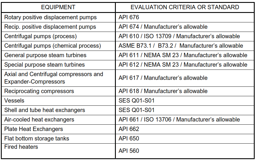
6.1 The allowable forces and moments on equipment nozzles shall be in accordance with Table-III.
6.2 Nozzle Loads in excess of the allowable loads shall be issued to Equipment manufacturer for
their design consideration.
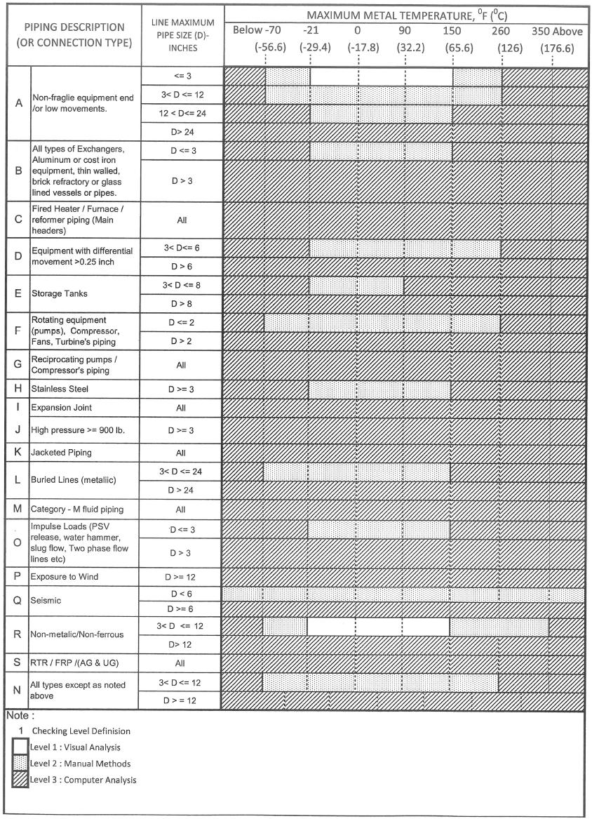
7 Criteria for Manual Calculations / Computer Analysis of a Piping System
The criterion for the selection of visual analysis, manual calculations or computer analysis is specified in Table-IV.
8 Computer Analysis
8.1 Analysis Requirements
8.1.1 All piping systems shall be evaluated and, if appropriate, analyzed for applicable conditions in accordance with ASME B31.3 and this practice. The Design Engineering Company personnel shall be qualified in accordance with the B31.3 Code para. 301.1.
8.1.2 The most severe, anticipated, coincident pressure and temperature conditions shall be considered to evaluate the flexibility and sustained load analyses for each anticipated operating conditions. Design conditions (pressure and temperature) shall be set in accordance with SES P01-E01. The sole uses for design conditions shall be in accordance with ASME B31.3 Appendix S, Example 1.
8.1.3 The flexibility analysis can require the combinations of more than one load case to determine the total displacement stress range.
8.1.4 Stress analysis shall be carried out using a CAESAR-II, latest version program. Sufficient number of runs shall be made to establish the most severe combinations of load cases for code compliance and nozzle load qualifications.
8.1.5 Due care to be taken to avoid interference with the other piping or structures due to thermal expansion of piping.
8.2 Stress Sketches
8.2.1 Calculations shall be supported by a Stress Sketches showing: elevations, distances, calculation nodes, items, restraints, distance from nozzle to equipment and relative displacements, etc. In the event of negligible variations, a justificatory note supporting the calculation made on a preliminary sketch shall be deemed sufficient.
8.2.2 Stress sketches shall normally be drawn on piping Isometrics. System isometrics may also be used if required.
8.2.3 Stress Sketches shall include the following:-
a. The Calculation number, revision, date of issue, stress engineer’s name & checkers name.
b. When stress sketches are revised they should clearly show a new revision number on each sheet and all changes are to be ballooned.
c. Relevant ‘Holds’ and ‘Notes’ required.
d. References to other stress calculations (where known) clearly showing the extent of the calculations referenced.
e. Assumptions made for the purpose of the calculation.
f. Future piping, where applicable, shall be modeled to prove the current piping layout will not be over-stressed.
g. Required piping reroutes.
h. Significant pipe support loads.
i. Pipe displacements larger than 50mm.
j. Location and types of pipe supports.
k. Spring supports shall be identified with an item code number, an operating load and
displacement. Note – the stress engineer shall complete the spring data sheet.
l. Rigid Struts shall be identified with an item code number and an operating load.
Note – the stress engineer shall complete the struts data sheet.
m. Location of slide plates.
n. Dimensions of equipment clearly showing location of fixed end.
o. Process conditions used in the calculation should be shown on the stress sketch front sheet.
p. Reinforcement pads on trunnion, branch reinforcements where required.
q. Supports from vessels or platforms mounted from vessels to be clearly indicated.
8.3 Calculation Report
8.3.1 The output report shall be with the following contents:
(i) Cover sheet
(ii) Piping stress isometric drawing with mark-up of node number, support points, analysis condition and any required information.
(iii) Reference documents. It is not necessary to include all these but all reference documents used ( such as P&ID’s, Line Lists, material specifications etc.) shall be noted along with the revision in the body of the report. If not referenced elsewhere then actual copies of reference
documents shall be included in the report.
(iv) Analysis input echo (geometry, material properties, and weights of piping components etc.)
(v) Displacement summary
(vi) Restraint summary & summary for hydro test load case.
(vii) ASME B 31.3, B 31.1, B 31.4 and B 31.8 code compliance report.
(viii) Rotating equipment compliance reports.
(ix) Data sheet for special item, such as spring hanger, expansion joint, etc.
(x) WRC calculations summary.
(xi) Flange leakage analysis report (if applicable).
(xii) Dynamic analysis report (If applicable).
a. Computer generated graphics to verify the input data and results of analysis.
b. Dynamic capability for fluid transient, vibration, earthquake analysis etc. Refer to SES P01-E11, SES P01-E12 & SES P01-E13 for details.
2 References
Reference is made in this standard to the following documents. The latest issues, amendments, and supplements to these documents shall apply unless otherwise indicated.
SABIC Engineering Standards (SES)
B01-E01 Design Criteria for concrete and steel structures
G13-S01 Reciprocating Compressor for Process Service
G23-E02 Typical Piping Arrangement for Centrifugal Pumps and Compressors
P01-E01 Design of Plant Piping and Transportation pipelines
P01-E08 Cold spring and expansion joints
P01-E09 Plant Lay-out, Spacing, and Clearances
P01-E11 Dynamic effects on piping systems due to impulse loads
P01-E12 Dynamic effects on piping systems due to Harmonic loads
P01-E13 Dynamic effects on piping systems due to Seismic loads
Q01-S01 Pressure Vessels “General”
American Society of Mechanical Engineers (ASME)
B 31.1 Power Piping
B 31.3 Process Piping
B31.4 Pipeline Transportation System for Liquid Hydro Carbons and Other Liquids
B31.8 Gas Transmission and Distribution Piping Systems
B 73.1 Specification for Horizontal and End Suctions Centrifugal Pumps for Chemical Process.
B 73.2 Specification for Vertical In-line Centrifugal Pumps for Chemical Process.
ASME Boiler and pressure vessel code section III Division I – Sub section NC
American Petroleum Institute (API)
API 560 Fired Heaters for General Refinery Services.
API 610/ISO 13709 Centrifugal Pumps for Petroleum, Petrochemical, and Natural Gas Industries.
API 611 General Purpose Steam Turbines for Petroleum, Chemical, and Gas Industry services.
API 612 Special Purpose Steam Turbines for Petroleum, Chemical, and Gas Industry services.
API 617 Axial and Centrifugal Compressors and Expander-compressors for Petroleum, Chemical, and Gas Industry services.
API 618 Reciprocating Compressors for Petroleum and Gas Industry Services.
API 620 Design and construction of Large, welded low pressure storage tanks.
API 650 Welded Steel Tanks for Oil Storage.
API 661 / ISO 13706 Air-Cooled Heat Exchangers for General Refinery Service.
API 662 Plate Heat Exchangers for General Refinery Services part-I.
API 674 Positive Displacement Pumps-Reciprocating.
API 676 Positive Displacement Pumps – Rotary.
API RP 686, Part-2 Recommended practice for machinery installation and installation design
API RP 688 Pulsations and Vibration Control in Positive Displacement Machinery Systems for Petroleum, Petrochemical, and Natural Gas Industry Services.
National Electrical Manufacturers Association Inc. (NEMA)
SM-23 Steam Turbines for Mechanical Drive Service
Process Industry Practices (PIP)
PNC00001 Piping support criteria for ASME B31.3 Metallic Piping.
PNC00004 Piping stress analysis criteria for ASME B31.3 Metallic Piping.
Welding Research Council (WRC)
Bulletin 107
Bulletin 297