This Article is for standard piping supports, and covers guides, shoes, axial restraints, dummy extensions, base supports, field supports, and compressor line clamps. The supports in this article cover both insulated and uninsulated piping. It will be useful if shall be used in conjunction with the pipe support standard drawings in the series SES P19-G01 to P19-G07.
2. References
Reference is made in this standard to the following documents. The latest issues, amendments and supplements to these documents shall apply unless otherwise indicated.
SABIC Engineering Standards (SES)
P01-E09 Plant Layout, Spacing, and Clearances
P19-G01 Selection of Standard Pipe Guides and Pad
P19-G02 Selection of Standard Pipe Shoes
P19-G03 Selection of Standard Axial Restraints
P19-G04 Selection of Standard Dummy Extensions
P19-G05 Selection of Standard Base Supports
P19-G06 Selection of Field Pipe Supports
P19-G07 Selection of Compressor Line Clamps
Q01-G02 Surface Preparation and Painting
W12-F02 Welding & Inspection of Hangers and Supports.
American Society for Testing and Materials (ASTM)
ASTM A 53 Specification for Pipe, Steel, Black and Hot-Dipped, Zinc-Coated Welded and Seamless.
American Welding Society (AWS).
AWS D1.1 American Welding Society Structural Welding Code
Manufactures Standardization Society (MSS)
MSS SP-58 Pipe Hangers and Supports – Materials, Design and Manufacture.
4. General Requirements
4.1 Standard pipe supports listed in this standard are pre-engineered for selection within the window provided for allowable loads.
4.2 Any deviation from this standard, or the SES P19-G01 to P19-G07 series of standard pipe support drawings, shall constitute a nonstandard support.
4.3 All hardware shall be selected from a manufacturer that conforms to MSS SP-58.
4.4 A standard pipe support drawing index is given in Appendix A.
4.5 Pipe support selection charts are given in Appendix B.
4.6 The correlation between the pipe support standard selection charts and drawing details and their relevant SES number is given in Table I.
5. Design Limitations
5.1 Design Criteria
5.1.1 Design Parameters. Supports have been designed to provide adequate support at maximum support spacing specified in SES P01-E09. Service temperature, pipe wall thickness and hydrostatic loads have been considered in the design.
5.1.2 Selection Tables. Selection tables and load limits have been provided to enable correct support application. All supports are identified with a unique symbol or code identifying type and material of construction.
5.2 Materials
Materials of construction of the pipe supports shall be specified in the individual pipe support standard drawings.
5.3 Welding and Postweld Heat Treatment
All welding, other than attachment to pressure piping, shall conform to AWS D1.1. All welding and Postweld heat treatment to pressure piping shall be in accordance with SES W12-F02.
5.4 Service Limitations
The standard supports shall not be used in the following situations:
a. Vacuum service
b. Cold insulated piping
c. Acoustically insulated piping
5.5 Design Limitations
Stress analysis shall be required when any of the following conditions exist:
a. Temperature of minus 29 °C and below
b. Pipe operating pressure above 20.7 kPa
c. Piping is to or from reciprocating compressors or pumps
d. Lines in hydrogen service
e. Lines in oxygen service
f. Lines in category M service
g. If columbium stabilized steels (type 347 ss) thicker than standard weight, or exceeding 6 mm thickness are used.
6. Fabrication
6.1 Pipe Support Locations
The type and location of the required pipe supports shall be shown on the piping drawings, or piping isometric drawings.
6.2 Responsibility
The responsibility for furnishing and installing pipe supports shall be as follows.
6.2.1 Pipe Spool Fabricator. The pipe spool fabricator shall be responsible for fabrication and attachment of all weld-on supports, and pads on shop fabricated piping.
6.2.2 Field. The construction contractor shall supply and install all supports, pads, field fabricated piping and random pipe. Construction contractor shall also supply and install bolt-on supports, field supports, and the auxiliary steel shown on the standard drawings.
6.3 Dimensions
The standard support drawings shall provide the dimensions for the supports for various pipe sizes.
6.4 Structural Shapes
The standard support drawings shall show dimensions and weights of a fabricated part, with dimensions in SI units.
6.5 Protective Coatings
All carbon and low alloy steel supports shall be hot dip galvanized except for field weld surfaces. Field welds and adjacent surfaces shall be painted after welding, in accordance with the procedure for repair of galvanized surfaces specified in ASTM A 53. Coatings for stainless steel shall be in accordance with SES Q01-G02.
6.6 Marking
Each support shall have its identifying code marked on a web or other nonbearing surface. Marking of austenitic stainless steel shall be done using paint or ink which contains no harmful chemicals, for example zinc, copper or any other ingredient which may cause corrosive attack on the base metal upon heating.
6.7 Shipping
6.7.1 All compressor line clamps shall be shipped completely assembled.
6.7.2 Bases for supports that require field adjustment shall be tack welded to the support.
6.7.3 Supports that require slide plates shall have the slide plates suitably protected and securely
attached to the support.
7. Erection
7.1 Compressor Line Clamps
The clamp shall first be torqued finger tight, and then the number of additional turns shall be as shown in SES P19-G07. The torque shall be applied to the nut on top of structural shape or plate ‘A’ only, while the two lock nuts are backed off. After torquing, structural shape or plate ‘A’ shall be parallel to the top of support. Finally the two lock nuts shall be fully tightened.
7.2 Adjustments
If chatter occurs during service testing at operating temperature, additional torque shall be applied to stop chatter. The clamp shall not be tightened to the extent that restraint occurs in any direction other than intended by the clamp design.
| DETAIL NUMBER | SUPPORT TYPE | SES |
| 100-199 | Selection charts | P01-E06 |
| 200-300 | Pipe guides and pad | P19-G01 |
| 400-499 | Pipe shoes | P19-G02 |
| 500-505 | Axial restraints | P19-G03 |
| 600-699 | Dummy extensions | P19-G04 |
| 700-799 | Base supports | P19-G05 |
| 800-899 | Field supports | P19-G06 |
| 900-999 | Compressor line clamps | P19-G07 |
| DRAWING NUMBER |
DESCRIPTION |
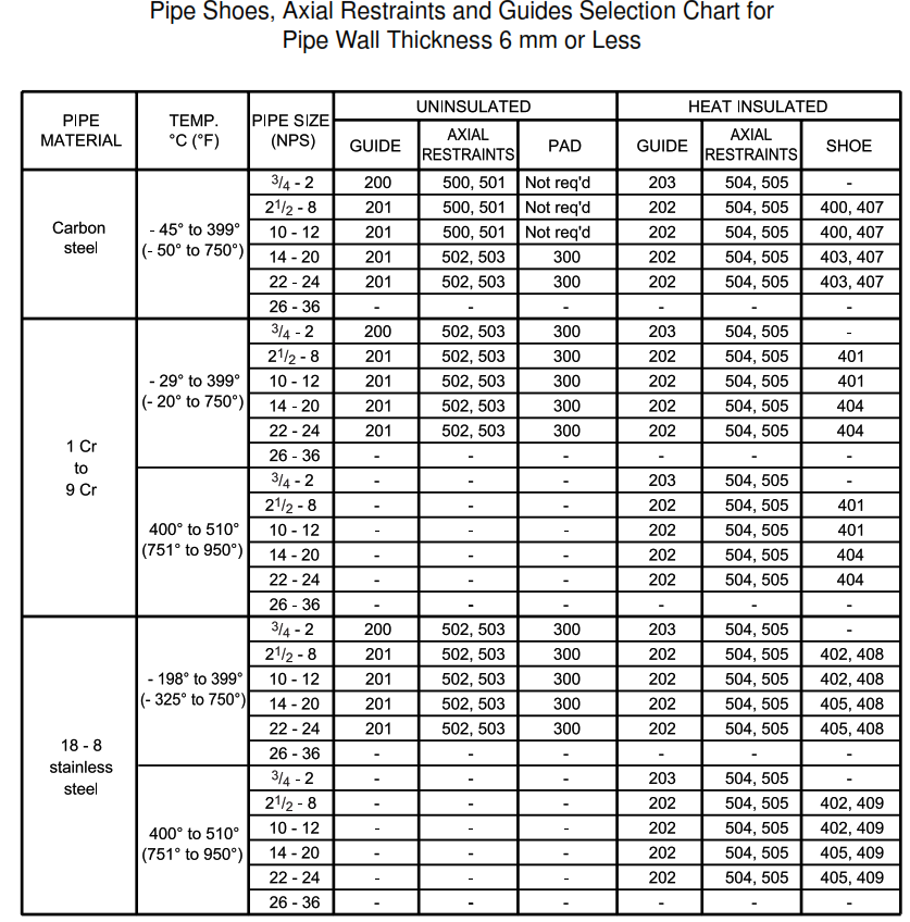
| DETAIL 100 | Pipe shoes, axial restraints and guides selection chart for pipe wall thickness 6 mm or less |
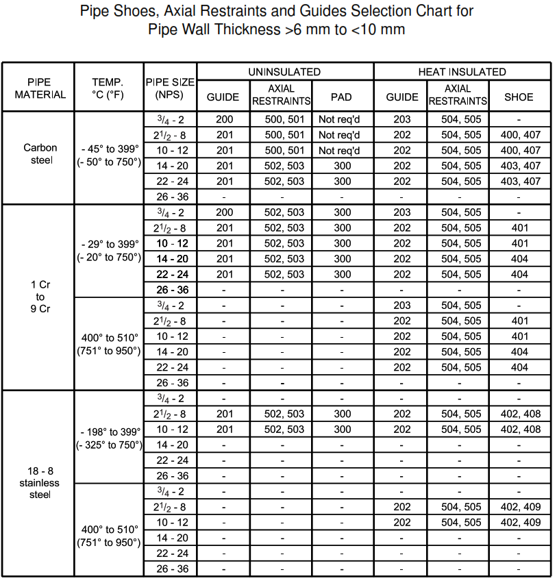
| DETAIL 101 | Pipe shoes, axial restraints and guides selection chart for pipe wall thickness >6 mm to <10 mm |
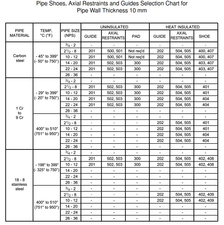
| DETAIL 102 | Pipe shoes, axial restraints and guides selection chart for pipe wall thickness 10 mm |
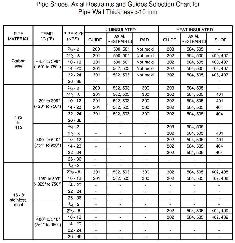
| DETAIL 103 | Pipe shoes, axial restraints and guides selection chart for pipe wall thickness >10 mm |
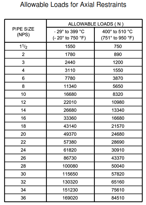
| DETAIL 104 | Allowable loads for axial restraints |
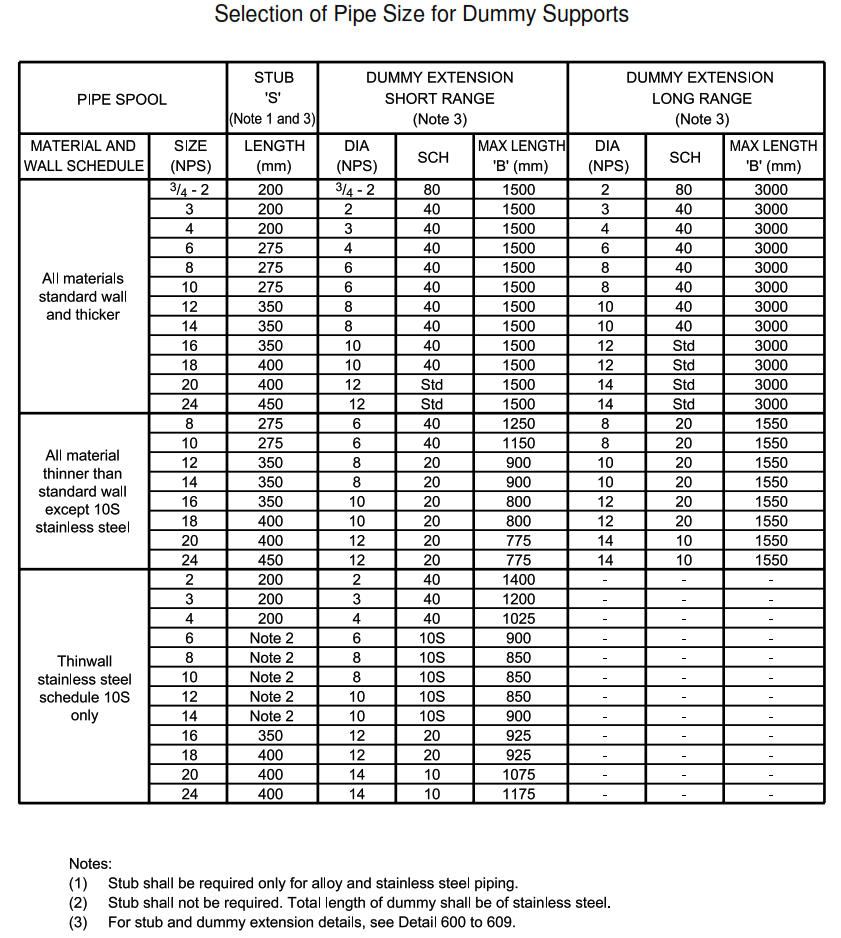
| DETAIL 105 | Selection of pipe size for dummy supports |
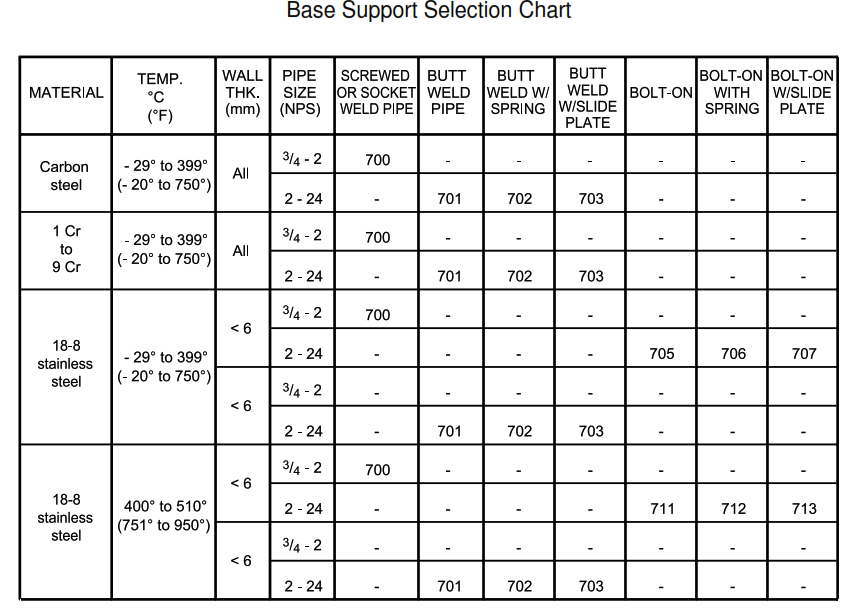
| DETAIL 106 | Base support selection chart |
| DETAIL 200 | Pipe guide for uninsulated pipe NPS 3/4 to 2 |
| DETAIL 201 | Pipe guide for uninsulated pipe NPS 21/2 to 24 |
| DETAIL 202 | Pipe guide for hot insulated pipe NPS 21/2 to 24 |
| DETAIL 203 | Pipe guide for hot insulated pipe NPS 3/4 to 2 |
| DETAIL 300 | Support pad for uninsulated pipe |
| DETAIL 400 | Pipe shoe for hot insulated carbon steel pipe NPS (2 to 8) |
| DETAIL 401 | Pipe shoe for hot insulated chrome pipe NPS (2 to 8) |
| DETAIL 402 | Pipe shoe for hot insulated stainless steel pipe NPS (21/2 to 8) |
| DETAIL 403 | Pipe shoe for hot insulated carbon steel pipe NPS (10 to 24) |
| DETAIL 404 | Pipe shoe for hot insulated chrome pipe NPS (10 to 24) |
| DETAIL 405 | Pipe shoe for hot insulated stainless steel pipe NPS (10 to 24) |
| DETAIL 407 | Bolt-on shoe for hot insulated carbon steel pipe NPS 21/2 to 24 |
| DETAIL 408 | Bolt-on shoe for hot insulated stainless steel pipe NPS 21/2 to 24 up to 399 °C (750 °F) |
| DETAIL 409 | Bolt-on shoe for hot insulated stainless steel pipe NPS 21/2 to 24 from 400 to 510 °C (751 to 950 °F) |
| DETAIL 410 | Pipe shoe notch to clear weld |
| DETAIL 500 | Axial restraint for uninsulated carbon steel pipe NPS 3/4 to 4 |
| DETAIL 501 | Axial restraint for uninsulated carbon steel pipe NPS 6 to 24 |
| DETAIL 502 | Axial restraint with pad for uninsulated pipe NPS 3/4 to 4 |
| DETAIL 503 | Axial restraint with pad for uninsulated pipe, NPS 6 to 24 |
| DETAIL 504 | Axial restraint for hot insulated pipe NPS 3/4 to 4 |
| DRAWING NUMBER |
DESCRIPTION |
| DETAIL 505 | Axial restraint for hot insulated pipe NPS 6 to 24 |
| DETAIL 600 | Dummy extension for uninsulated pipe, flat turned |
| DETAIL 601 | Dummy extension for uninsulated pipe, turned downward |
| DETAIL 602 | Dummy extension for uninsulated pipe, turned upward |
| DETAIL 603 | Dummy extension support for vertical uninsulated and hot insulated pipe |
| DETAIL 604 | Dummy extension support for uninsulated and hot insulated screwed pipe NPS 3/4 to 2 |
| DETAIL 605 | Dummy extension support for uninsulated and hot insulated socket weld pipe NPS 3/4 to 2 |
| DETAIL 606 | Dummy extension support for hot insulated pipe turned flat |
| DETAIL 607 | Dummy extension support for hot insulated pipe turned downward |
| DETAIL 608 | Dummy extension support for hot insulated pipe turned upward |
| DETAIL 609 | Dummy extension support shoe, NPS 21/2 to 14 |
| DETAIL 700 | Base support for socket weld and screwed pipe NPS 3/4 to 2 |
| DETAIL 701 | Base support for butt weld pipe NPS 2 to 24 |
| DETAIL 702 | Base support with spring support for butt weld pipe NPS 2 to 24 |
| DETAIL 703 | Base support with slide plates for butt weld pipe NPS 2 to 24 |
| DETAIL 704 | Slide plate assembly for base support NPS 2 to 24 |
| DETAIL 705 | Bolt-on base support, NPS 2 to 24 |
| DETAIL 706 | Bolt-on base support with spring NPS 2 to 24 |
| DETAIL 707 | Bolt-on base support with slide plate NPS 2 to 24 |
| DETAIL 711 | Bolt-on base support NPS 2 to 24 |
| DETAIL 712 | Bolt-on base support with spring NPS 2 to 24 |
| DETAIL 713 | Bolt-on base support with slide plate NPS 2 to 24 |
| DETAIL 714 | Concrete pad for base support used in unpaved areas |
| DETAIL 800 | Trapeze support for horizontal pipes |
| DETAIL 801 | H-frame type support for horizontal pipes |
| DETAIL 802 | Load support for NPS 2 and smaller vertical pipes |
| DETAIL 803 | Bolt-on guide for NPS 11/2 and 2 vertical pipes |
| DETAIL 804 | Guide for NPS 1 and smaller vertical pipe |
| DETAIL 805 | Cantilever support for horizontal pipe |
| DETAIL 806 | Cantilever bolt-on guide for uninsulated vertical pipe |
| DETAIL 807 | Cantilever pipe strap guide for uninsulated vertical pipe NPS 1 and under |
| DETAIL 808 | Cantilever guide for hot insulated vertical pipe |
| DETAIL 809 | Pipe hanger for uninsulated and hot insulated pipe |
| DETAIL 810 | Pick-up support from uninsulated pipe for horizontal pipes |
| DETAIL 811 | Pick-up support from insulated pipe for horizontal pipes |
| DETAIL 812 | Pick-up guide from uninsulated pipe for vertical pipes |
| DETAIL 813 | Pipe support for vertical pipe to platforms for pipe NPS 12 and under |
| DETAIL 814 | L-frame type support for horizontal pipes |
| DETAIL 815 | U-bolt guide |
| DETAIL 816 | Pipe strap guide |
| DETAIL 817 | U-bolt support |
| DETAIL 818 | Concrete column bolt-on plate |
| DETAIL 819 | Concrete beam bolt-on bracket |
| DETAIL 820 | Side mounted guide for uninsulated and heat insulated horizontal pipe NPS 3/4 to 2 |
| DETAIL 821 | Lugs for uninsulated and hot insulated pipe NPS 2 to 24 |
| DETAIL 900 | One direction restraint for uninsulated pipe NPS 11/2 to 6 |
| DETAIL 901 | One direction restraint for uninsulated pipe NPS 8 to 24 |
| DETAIL 902 | Two-direction restraint for uninsulated pipe NPS 11/2 to 6 |
| DETAIL 903 | Two-direction restraint for uninsulated pipe NPS 8 to 24 |
| DETAIL 904 | One direction restraint for hot insulated pipe NPS 11/2 to 6 |
| DETAIL 905 | One-direction restraint for hot insulated pipe NPS 8 to 24 |
| DETAIL 906 | Two-direction restraint for hot insulated pipe NPS 11/2 to 6 with insulation thickness 50 mm or less |
| DETAIL 907 | Two-direction restraint for hot insulated pipe NPS 8 to 24 with insulation thickness 50 mm or less |
Support Selection Charts
This appendix contains support selection charts. Numbers in the chart are detail numbers.
FAQs:
What are Category ‘M’ Fluid Services?
What is Hydrogen Service?