1 Scope ……………………………………………………………………………………2 Reference Documents …………………………………………………………………………………..3 Definitions……………………………………………………………………………………4 General……………………………………………………………………………..5 Positive Displacement (Rotary and Reciprocating) Pumps …………………………..6 Centrifugal Pumps ……………………………………………………………………………………7 Turbines ……………………………………………………………………………………8 Axial and Centrifugal Compressors and Expander-Compressors 9 Reciprocating Compressors ……………………………………………………….10 Vessels ……………………………………………………………………………………11 Shell and Tube Heat Exchangers ……………………………………………………….12 Air-cooled Heat Exchangers ……………………………………………………….13 Flat Bottom Storage Tanks ……………………………………………………….14 Fired Heaters ……………………………………………………………………………………15 Revision History…………………………………………………………………..Table I Nozzle Loadings ……………………………………………………………………………………FIGURE 1 – Piping Supporting Detail for Pumps …………………………..Figure 1A. Pumps Integrally Supported at Nozzle Centerline …………………………..Figure 1B. Pump Supported Below Nozzle Centerline …………………………..Figure 1C. Pump Supported Below Nozzles ……………………………………………………….Figure 1D. Pump Supported at Nozzle Centerlines …………………………..Figure 1E. Pump Supported Above Nozzle Centerlines …………………………..Figure 1F. Pump Supported Below Nozzle Centerlines …………………………..
1 Scope
1.1 This standard establishes a design basis for permissible piping loads on various plant
equipment nozzles, including centrifugal pumps, positive displacement pumps
(rotary), positive displacement pumps (reciprocating), turbines, centrifugal
compressors, reciprocating compressors, vessels, shell and tube heat exchangers,
air-cooled heat exchangers, flat bottom storage tanks, and fired heaters. ASME
B31.1, ASME B31.3, ASME B31.4, and ASME B31.8 codes shall form the basis for
calculating piping loads due to thermal, dead weight, seismic, wind, impulse, and
harmonic conditions where applicable.
1.2 This standard also provides requirements for minimizing loads imposed on
equipment by the piping system.
1.3
In case of conflict between the requirements specified herein and those stipulated
elsewhere in other SES and international codes and standards; the most stringent
requirements shall govern.
2 Reference Documents
Reference is made in this standard to the following documents. The latest issues,
amendments, and supplements to these documents shall apply unless otherwise indicated.
SABIC Engineering Standards (SES)
P01-E08 Cold Springing and Expansion Joints
Q01-S01 Pressure Vessels Carbon and Low Alloy Steels-General
American National Standards Institute (ANSI)
B73.1 Specification for Horizontal End Suction Centrifugal Pumps For Chemical Process
The American Society of Mechanical Engineers (ASME)
B31.1 Power Piping
B31.3 Process Piping
B31.4 Pipeline Transportation Systems For Liquid Hydrocarbons and Other Liquids
B31.8 Gas Transmission and Distribution Piping Systems
Section III Paragraph NC-3658-1
Section VIII Div. 2 Alternative Rules for pressure Vessels
American Petroleum Institute (API) & The International Organization for
Standardization(ISO)
560 Fired Heaters for General Refinery Services
610/ISO 13709 Centrifugal Pumps for Petroleum, Petrochemical, and Natural Gas Industries.
611 General Purpose Steam Turbines for Petroleum, Chemical, and Gas Industry services
612 Special Purpose Steam Turbines for Petroleum, Chemical, and Gas Industry services
617 Axial and Centrifugal Compressors and Expander-compressors for Petroleum,
Chemical, and Gas Industry services
650 Welded Steel Tanks for Oil Storage, Tenth Edition
620 Design and construction of Large, welded low pressure storage tanks
661 Air-Cooled Heat Exchangers for General Refinery Service
676 Positive Displacement Pumps – Rotary
ISO 13706 Petroleum, petro-chemical and Natural Gas industries-Air cooled exchangers.
RP 686, Part-2 Recommended practice for machinery installation and installation design.
National Electrical Manufacturers Association Inc. (NEMA)
SM-23 Steam Turbines for Mechanical Drive Service
Welding Research Council (WRC)
Bulletin 107
Bulletin 297
3
Definitions
Allowable Nozzle Load. The allowable nozzle load is defined as the lesser of a) to c):
a. The load at which the most severely stressed fiber reaches the allowable stress
defined in the applicable code for the equipment
b. The load at which either strain or deformation exceeds the limits provided by the
equipment design specification
c. The load at which loss of component or support function occurs, as defined by the
equipment design specification
Anchor. A rigid restraint providing full fixation in all six degrees of freedom, permitting
neither translatory nor rotational displacement of the pipe.
Critical Equipment. Equipment that is considered essential for successful, continuing
operation of a process, a unit, or plant.
Guide. A rigid restraint that restrains translational displacement perpendicular to the
longitudinal axis of the pipe, but allows translational and rotational movement in the
remaining five degrees of freedom.
Hold Down Restraint. A type of piping restraint consisting of a half clamp fitted around half
the outer circumference of the pipe and secured to a fixed structural or concrete member
through a series of bolts. Utilized to control vibration amplitudes in piping subject to dynamic
low frequency vibration from sources, for example fluid pulsations or rotational equipment
imbalances.
Rigid Strut. A restraint device usually consisting of a rigid member between two pinned end
connections with one pinned end attached to the pipe at one end and the other pinned end
attached to a fixed member at the other end, for the purposes of preventing translational
displacement along the axis of the device but permitting displacement and rotation in the
remaining degrees of freedom. Most rigid struts function in both tension and compression.
Cold Spring. The method of inducing stresses in the pipe by cutting the pipe short by a
percent of the expected thermal growth and then mechanically pulling the pipe to close the
gap.
4 General
4.1 Forces and moments imposed on rotating equipment nozzles shall not exceed the
allowable forces and moments as prescribed by the manufacturer. If manufacturer‟s
allowables are unavailable, calculated forces and moments shall not exceed the
loading limits specified in Table I. In the absence of manufacturer‟s allowable data,
and if the equipment is not purchased in accordance with Table I criteria, the
contractor shall submit calculated forces and moments to the manufacturer for
approval. If the manufacturer‟s allowables are used, then the coordinate system shall
be mutually agreed upon between SABIC and the manufacturer.
4.2 Attached are layout guidelines of piping support arrangements for various types of
pumps.
4.3 As depicted in the attached figures base supports for supporting pump piping are
utilized near pump nozzles where the pump is integrally supported at the pump
centerline. The remaining figures utilize spring supports to allow for the thermal
expansion of the pump casing for those applications where the pump nozzles are not
integrally supported at the pump centerline.
4.4 Piping restraints such as anchors, guides, and rigid struts that are used to limit forces
and moments on rotating equipment nozzles shall be designed to limit restraint
deflection under load. Calculations shall consider the structural stiffnesses of
restraints near rotating equipment.
4.5 Calculation of piping loads shall include the following considerations:
a. Weight of the piping system and its contents
b.
Thermal movement of the pipe and machinery due to process fluid
temperature changes, including start-up, shutdown, clean-out, and off-design
operation, as well as the normal operating temperature cases
c. Movement of the pipe, machinery, and support systems due to thermal
distortion from the sun, weather, radiant heating from nearby equipment, and
process flow effects
d.
Heat tracing
e.
Differential settlement of foundations and/or frost heaving
f.
Reactions from restraints such as anchors, pins, and ties
g. Other attached piping that may exert significant loading
h. Adjacent equipment attached to the same header
4.6 Piping loads applied to machinery nozzles shall be calculated if any of the following
conditions exist:
a. Pipe size 3” NPS or larger
b. System temperature in excess of 300 F or -150 F and below
c.
Critical machinery
d. Machinery with a history of nozzle load sensitivity/problems, either for a
particular application or for a particular machinery type
4.7 When applicable or when specified, the following considerations shall also be
included in the analysis:
a.
Friction forces from piping supports, guides, and restrictions for critical lines
b.
Unsteady operation, such as two phase flow or vibration
c. Pulsating flow
d. Wind loading
e. Maintenance requirements, including the installation and removal of blinds,
startup strainers
f.
Steam-out conditions
g. Equipment (such as instruments) supported by the piping
h. Seismic loading
i. Decoking
j.
Regeneration
k. Start-up
4.8 Flange misalignment at rotating equipment shall be checked by performing analysis
with:
a. Piping disconnected from equipment flange
b. Pipe temperature at ambient temperature
c. Spring supports considered as rigid supports
d. Commodity excluded from analysis
4.9 Friction loads must not be used as a tool to provide an “advantage” to the system
design, for example: where it can lower loads at equipment nozzles or supports.
Stress analysis runs with and without friction shall be carried out to establish the
worst case condition. The friction co-efficient values which will be considered during
analysis are furnished for guidance as below :
a. Steel to Steel 0.3
b. Teflon to Teflon (PTFE) 0.1
c. Steel to concrete 0.45
4.10 Thermal displacements of rotating and stationary equipment shall be considered in
the piping stress analysis.
4.11 The maximum permissible spring support load variation for piping connected to
rotating equipment shall be limited to 10 percent.
4.12 To avoid leakage at equipment nozzle flanges, bending moments and forces shall be
limited by the formulas listed in the ASME Section III, Paragraph NC-3658-1
4.13 An additional stress load case shall be considered during stress analysis when the
line list indicates that hydraulic test as required. In this case, the calculation shall be
performed considering erection temperature of the system, internal test fluid weight,
test pressure, weight of insulation etc.
4.14 Wind Analysis is to be considered as an occasional load case during stress analysis
and it should not be combined with other occasional load cases such as earth quake
loading. Wind analysis requirements for piping shall duly take into consideration the
project design basis and Owner supplied environmental data for the site.
4.15 While calculation of seismic force required during seismic analysis of piping, Owner
supplied site environmental data and other applicable SES standards shall be duly
considered for arriving at the Earth quake zone which is applicable for the site.
4.16 An Anchor support shall be considered for safety valve piping during the analysis.
When two or more safety valves are in parallel, stress analysis shall consider the
different operating conditions. All reaction forces during safety valve(s) blow-off shall
be accounted in the piping stress analysis.
4.17 The piping loadings on stationary and rotating equipment nozzles shall also be
qualified at design conditions of the connected piping during stress analysis. In case
of difficulty in meeting this requirement for critical rotating machinery, (For example:
cracked gas compressors, synthetic gas compressors or such large size machinery)
specific approval from Owner may be obtained by furnishing sound technical
justification.
5
Positive Displacement (Rotary and Reciprocating) Pumps
5.1 Calculated nozzle forces and moments for rotary and reciprocating positive
displacement pumps shall not exceed the allowable forces and moments prescribed
by the manufacturer. Calculated forces and moments shall be submitted to the
manufacturer for review and approval in the absence of manufacturer allowable
loads. In the absence of Manufacturer‟s allowable forces and moments, calculated
nozzle forces and moments shall not exceed the loading limit specified in Table-I
5.2 Suction and discharge piping to positive displacement reciprocating pumps shall
contain holddown restraints on piping to minimize the potential of pulsation loading
on pump nozzles should pulsation dampeners become inoperative.
6 Centrifugal Pumps
6.1 Calculated nozzle forces and moments for centrifugal pumps shall not exceed the
allowable forces and moments prescribed by the manufacturer. In the absence of
manufacturer allowable forces and moments, calculated nozzle forces and moments
shall not exceed the loading limits specified in Table I. Forces and moments
exceeding the limits specified in the loading criteria in Table I shall satisfy the
requirements of API 610 Appendix „F‟. The methods furnished in Annexure-F may be
used only if approved by “Owner”. The applied Forces and moments acting on each
pump nozzle shall be translated to the centre of the pump..
6.2 The effect of spare pump piping shall be considered in the thermal analysis of all
pump piping systems.
6.2.1 The metal temperature of the interconnecting spare pump piping shall be
considered to be at the minimum ambient temperature if no hot (warm-up)
minimum flow by-pass piping is present and if no rigorous heat transfer
calculations are performed.
6.2.2 If a hot (minimum flow) by-pass is included in the piping system, the metal
temperature of the interconnecting spare pump piping shall be taken as the
design temperature.
6.3 The use of expansion joints in centrifugal pump piping shall conform to SES P01E08.
6.4 To minimize the damaging effects of water hammer and other impulse type loading
on pump nozzles, consideration shall be given to locating swing type check valves in
discharge lines in the vertical position above rigidly supported elbows so that hammer
loads may be distributed to grade or steel.
7 Turbines
7.1 Calculated nozzle forces and moments for general purpose steam turbines and
special purpose steam turbines shall not exceed the allowable force and moment
limits specified by the manufacturer. In the absence of manufacturer allowable forces
and moments, calculated nozzle forces and moments shall not exceed the loading
criteria specified in Table I. The combined resultant of the forces and moments of the
inlet, extraction and exhaust connections shall be resolved at the centerlines of the
exhaust flange (NEMA SM-23).
7.2 Supports for inlet, extraction and exhaust piping shall be arranged so that the dead
load imposed on the turbine nozzle is minimized.
7.3 Pressure safety valve discharge lines shall be supported in such a manner that the
relieving force during discharge does not impose loading in excess of the
manufacturer‟s recommended allowable nozzle loading.
7.4
In order to minimize the forces and moments at direct connections between the
turbine exhaust and surface condenser, an expansion joint, may be used.
8 Axial and Centrifugal Compressors and Expander-Compressors
8.1 Calculated nozzle forces and moments for centrifugal compressors shall not exceed
the allowable force and moment limits specified by the manufacturer. In the absence
of manufacturer allowable forces and moments, calculated nozzle forces and
moments shall not exceed the loading criteria specified in Table I. The combined
resultant forces and moments of the inlet, side stream, and discharge nozzles
resolved at the centerline of the largest connection as per API-617.
8.2 Silencers installed in the inlet and exhaust piping shall be properly supported and
guided to minimize wind and vibration loading on compressor nozzles.
8.3 Supports for inlet and exhaust piping shall be arranged so as to minimize the dead
load on the compressor nozzle.
9 Reciprocating Compressors
9.1 A static, pulsation and mechanical analysis shall be conducted on piping systems for
reciprocating machinery or machinery subject to pulsating flows. See API RP
686,Part-2 Chapter-6,
9.2 Calculated nozzle forces and moments for reciprocating compressors shall not
exceed the allowable limits specified in the loading criteria in Table I. Calculated
nozzle forces and moments for reciprocating compressors shall be submitted to the
manufacturer for review and approval in the absence of manufacturer allowable
loads.
9.3 Adjustable supports shall be provided for all pulsation dampeners not directly
mounted on top of compressor cylinders. These adjustable supports shall minimize
forces and moments at the cylinder/dampener interface by supporting the dampener
weight while allowing thermal displacement along the cylinder axis as well as
preventing dynamic movement along the major axis of the dampener.
9.4 Hold down piping supports shall be designed and oriented so as to minimize
thermally induced forces and moments at pulsation dampener nozzles.
10 Vessels
Calculated nozzle forces and moments at vessel nozzles shall not exceed the value specified
in SES Q01-S01 Paragraph 5.13. Incase these loads exceeds the limit given, a local stress
analysis shall be carried out (as detailed in WRC 107), and these local stresses shall be
compared to allowable stresses established in ASME Section VIII, Div. 2, WRC Bulletin 107,
and its supplement WRC 297.
11 Shell and Tube Heat Exchangers
Calculated nozzle forces and moments at vessel nozzles shall not exceed the value specified
in SES Q01-S01 Paragraph 5.13. Incase these loads exceeds the limit given, a local stress
analysis shall be carried out (as detailed in WRC 107), and these local stresses shall be
compared to allowable stresses established in ASME Section VIII, Div. 2, WRC Bulletin 107,
and its supplement WRC 297.
12 Air-cooled Heat Exchangers
12.1 Calculated nozzle forces and moments on air-cooled heat exchangers shall not
exceed the allowable limits specified in the loading criteria in Table I.
12.2 It is recommended that two times API 661 loads be requested for allowable nozzle
loading during the request for quotation stage (RFQ) of the equipment procurement
process.
13 Flat Bottom Storage Tanks
13.1 Calculated nozzle forces and moments for „low type‟ conditions shall not exceed the
allowable limits specified in the loading criteria in Table I.
13.2 Calculations shall include displacements resulting from thermal expansion and tank
foundation settlement due to both hydrostatic testing and commodity weight.
14 Fired Heaters
14.1 Calculated nozzle forces and moments for fired heaters purchased to API 560 shall
not exceed the allowable limits specified in the loading criteria in Table I.
14.2 If the fired heater piping analysis incorporates the heater coil connections in the
model, the calculated displacements at the nozzle/ shell interface shall be submitted
to the equipment vendor for review and approval.
14.3 The effect of expansion and/or displacement of the tubes shall be reflected in the
computer analysis. Computer analysis of piping systems connected to floating heater
coils shall include the heater coil or an approximate model of the coil as part of the
system and the effects of internal guides and restraints. When heater coils are
floating, the supports of the connecting piping system shall be completely and
independently balanced so that no dead load is imposed on the coil.
Table-I Nozzle Loadings
| EQUIPMENT | EVALUATION CRITERIA OR STANDARD |
| Rotary positive displacement pumps | API 676 |
| Recip. positive displacement pumps | Manufacturer‟s allowables |
| Centrifugal pumps (refinery service) | API 610/ISO 13709 |
| Centrifugal pumps (chemical service) | ANSI B73.1 |
| General purpose steam turbines | API 611/NEMA SM 23 |
| Special purpose steam turbines | API 612/NEMA SM 23 |
| Axial and Centrifugal compressors and
Expander-Compressors |
API 617 & Manufacturer‟s allowable |
| Reciprocating compressors | Manufacturer‟s allowables |
|
Vessels |
SES Q01-S01 Paragraph 5.13 / WRC
107/WRC 297 |
|
Shell and tube heat exchangers |
SES Q01-S01 Paragraph 5.13 / WRC
107/WRC 297 |
| Air-cooled heat exchangers | API 661/ISO 13706 |
| Flat bottom storage tanks | API 650 |
| Fired heaters | API 560 |
FIGURE 1 – Piping Supporting Details for Pumps
Figure 1A. Pumps Integrally Supported at Nozzle Centerline
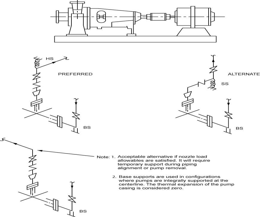
Figure 1B. Pump Supported Below Nozzle Centerline

Figure 1C. Pump Supported Below Nozzles

Figure 1D. Pump Supported at Nozzle Centerlines
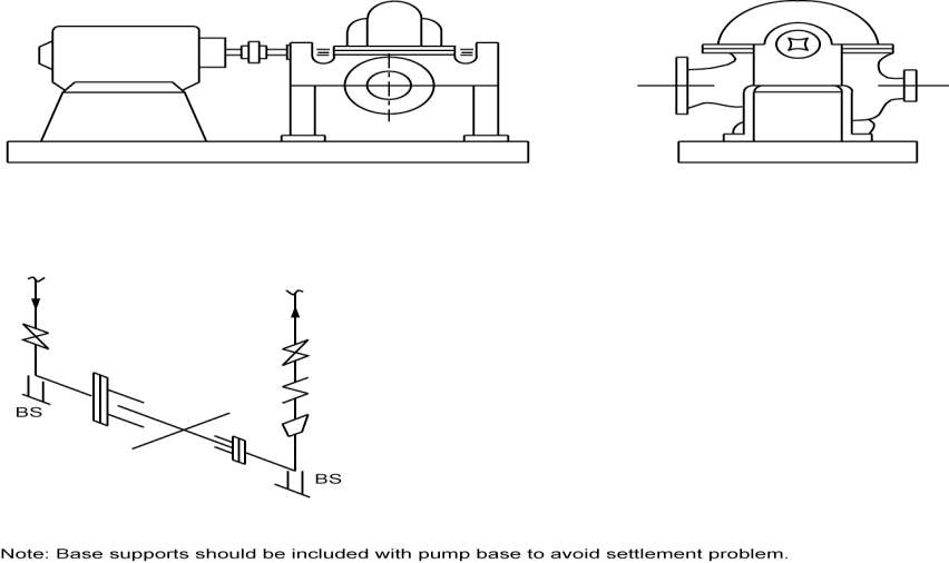
Figure 1E. Pump Supported Above Nozzle Centerlines

Figure 1F. Pump Supported Below Nozzle Centerlines
