What is Cold Spring in Piping?
Cold spring in piping refers to intentionally introducing a slight, controlled deformation or compression in a piping system during its installation or assembly. This deformation is typically applied to the pipe or components when they are at a lower temperature than the intended operating temperature. The purpose of cold spring is to compensate for the thermal expansion that will occur when the piping system is brought up to its normal operating temperature.
Here’s how cold spring works and why it’s used:
- Thermal Expansion: All materials expand when heated and contract when cooled. In a piping system, especially one that carries hot fluids, the pipes will expand as they heat up during operation. If the system is rigidly anchored at all points, this thermal expansion can lead to excessive stresses, distortion, or even pipe failure.
- Cold Installation: Cold spring is applied during the initial installation of the piping system when the pipes and components are at a lower, or “cold,” temperature. At this point, the system is assembled with a deliberate gap or space between anchor points.
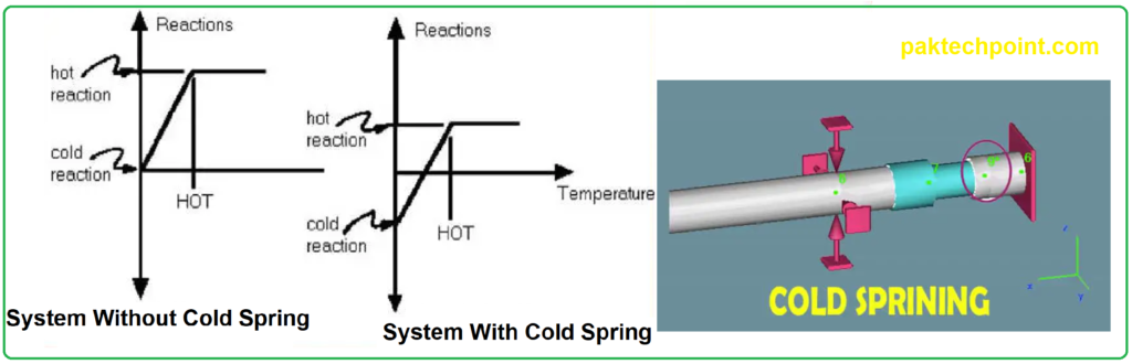
- Compression: Once the system is assembled with gaps or spaces, it is typically anchored in place. This anchoring creates a slight compression in the piping components, effectively preloading them. The amount of compression is carefully calculated to ensure that when the system heats up during operation, the compressed components will expand and fill the gaps, reducing or eliminating any movement or stress issues.
- Thermal Expansion Compensation: As the piping system heats up during operation, the components expand. However, because of the initial compression (cold spring), this expansion is absorbed, and the components move into the gaps or spaces created during installation. This compensates for the thermal expansion and prevents excessive stress or distortion.
Cold spring is a technique used to manage thermal expansion and ensure the integrity and safety of a piping system. It requires careful calculation and engineering to determine the appropriate amount of cold spring to apply, as excessive or insufficient cold spring can lead to operational problems or component failure. Properly applied cold spring helps maintain the stability and reliability of a piping system, especially in high-temperature applications.
This article provides background information and requirements for incorporating cold spring and expansion joints in piping systems and supplements the requirements of ASME B31.1, ASME B31.3, ASME B31.4, and ASME B31.8.
Cold Springing Technical Explanation
Cold Spring
The use of cold spring to reduce reaction loads at equipment nozzles is prohibited. The use of cold spring to reduce thermal movements and reaction loads in all other applications shall be subject to approval by the Plant Owner’s engineer.
For instances in which Owner’s approval is obtained, the requirements for cold spring outlined in ASME B31.3 Par. 319, 335, and 341 shall apply.
For purposes of controlling extreme movements in locations such as piperacks as well as providing a 2 /3 credit for reactionary forces at pipe anchors, the recommended cold spring factor as referenced in paragraph 319.5.1 of ASME B31.3 shall be taken as 0.5.
For piping systems subject to cold spring, spring supports shall remain locked with travel stops in place until cold spring and fit-up is completed. Spring support rod lengths shall be readjusted during cold springing to accommodate cold positioning of pipe. Prior to start-up, spring travel stops shall be removed and cold load settings verified. Spring supports shall not be used as “come alongs” with stops removed to cold spring piping into position.
Expansion Joints
The use of expansion joints as a means of providing flexibility in piping systems shall be subject to approval by the Owner’s engineer. For instances in which Owner’s approval is obtained, the requirements outlined in The Expansion Joint Manufacturers Association shall apply. The expansion joint arrangement shall be reviewed by the Owner’s engineer and the expansion joint manufacturer.
Piping Layout Considerations
a. All bellows expansion joint systems shall be equipped with adequate pressure thrust restraints, either inherent through hardware or with physical piping anchors.
b. Piping system drawings shall specify all anchors, guides, supports, and fixed points.
c. Anchors and guides shall be designed for the highest pressures in the system.
d. Expansion joints shall be located as close to an anchor as possible with the first pipe guide located at a maximum distance of four pipe diameters from the end of the bellows.
e. The distance from the first pipe guide and the second pipe guide from an expansion joint shall be a maximum of fourteen pipe diameters.
Design
a. The piping flexibility analysis shall incorporate the manufacturer’s bellows spring constants as well as any calculated pressure thrust loading on the piping, as required.
b. Bellows allowable stresses shall be based on the maximum temperature shown on the specification drawing.
c. Bellows pressure stresses for single ply design shall meet the requirements set forth in Appendix X of the ASME B31.3 Code.
d. Bellows pressure stresses for double ply design shall meet the following criteria:
Bellows Pressure Stresses (Double Ply Design)
S2 <= 0.5 Sall
S3 <= 0.5 Sall
S3 + S4 <=1.25 Sall
Where:
Sall = Basic allowable stress in tension at the design temperature for the bellows material. S2,S3,S4 = Calculated stresses obtained from the performance equations in the EJMA Standards.
e. Bellows deflection stresses for single and double ply design shall meet the following criteria as stipulated in ASME B31.3, Appendix X: 0.7 (S3+S4) + S5 + S6 < = SA
where: S3,S4,S5,S6 = Calculated stresses obtained from the performance equations in the EJMA Standards.
SA = Allowable stress value from the design fatigue curve, Fig. X302.1.3, in Appendix X, of the ASME B31.3 Code for cycle life, Nc = 1000 cycles.
f. The allowable stress on all hardware components shall be within the limits set by ASME B31.3.
g. Hinges, gimbals, and tie rods shall be designed to withstand the pressure and velocity thrust as
well as the spring rate of the bellows and any itemized external loads specified.
h. Pins in hinges, gimbals, and tie rods shall be designed so that they are in double shear.
i. The temperature used to design the expansion joint hardware shall be the same as the temperature used to design the bellows.
j. Each expansion joint assembly shall be provided with limit stops to protect the bellows for displacements in excess of those specified.
k. Lifting devices, designed to withstand an impact factor of twice the weight of the assembly, shall be provided for field handling and assembly.
l. All expansion joints shall be furnished with a protective, removable, external steel cover to protect the bellows.
Fabrication
Expansion joint bellows shall be hydraulically or mechanically formed from a tube having only longitudinal seams and a thickness before forming of 0.035 inch.
Nondestructive Testing and Examination
a. The requirements of ASME B31.3 Appendix X shall serve as abasis for the criteria and
procedure for testing and examination.
b. Expansion joints shall be hydrotested by the manufacturer at the test pressure specified on the specification drawing and shall be witnessed by the engineering contractor.
c. Only water having less than 50ppm chlorides shall be used for hydrostatic testing of austenitic stainless materials.
d. The longitudinal seams of the bellows shall be examined in accordance with Appendix X of the ASME B31.3 code before the bellows are convoluted. The entire bellows assembly shall be dye penetrant tested after forming and welding but before hydrostatic testing.
e. Longitudinal pipe welds and girth welds shall be examined by 100% radiographic and liquid penetrant examination.
f. All liquid penetrant tests shall be witnessed by the engineering contractor.
g. Records of all testing and examination shall be available to SABIC or its engineering contractor.
Identification, Tagging, and Shipping
a. Each assembly shall be identified with its assembly tag number according to the specification drawing.
b. Rated pressure, temperature, axial movement, lateral movements, and angulation shall be
indicated on a permanent tag attached to the expansion joint.
c. Expansion joints must have the flow direction clearly marked and permanently attached on the
assembly in two places, 180 degrees apart.
d. Each expansion joint shall be completely preassembled and packaged as an individual unit.
There shall be no loose pieces.
e. The vendor shall provide and clearly mark shipping bars with instructions for removal only after
installation of the expansion joint assembly in the piping system.
f. A copy of installation instructions shall be inserted in a plastic envelope and enclosed with its
respective assembly.
g. Components required for completion of any assembly and noted on the specification drawing
shall be shipped together by the supplier.
h. Material should be on pallets with a gross weight not to exceed 2,000 lbs. where practical.
i. The entire assembly shall be adequately protected against the elements or any corrosive
environment that could harm the assembly during shipping and storage.
Installation
a. Shipping bars shall be provided and clearly marked with instruction for removal only after the expansion joint assembly and the piping systems have been completely installed.
b. Shipping bars shall be installed with the expansion joint in the preset configuration, when specified.
c. If shipping bars cannot be used for lifting, field handling, or supporting the assembly, they must be clearly tagged to avoid damage to the bellows.
d. Expansion joints shall not be used to correct piping misalignment caused by field or erection errors.
Reference Documents and Codes
Reference is made in this standard to the following documents. The latest issues, amendments, and supplements to these documents shall apply unless otherwise indicated.
SABIC Engineering Standards (SES)
P01-E01 Design Conditions and Basis for Pressure Piping
P01-E02 Design of Piping Systems for Stress and Pressure Criteria
P01-E03 Pressure Design of Piping Components
P01-E04 Flexibility, Support, and Anchors
P01-E07 Forces and Moments on Equipment Nozzles
American Society of Mechanical Engineers (ASME)
B 31.1 Power Piping
B 31.3 Process Piping; Appendix X
B 31.4 Liquid Petroleum Transportation Piping
B 31.8 Gas Transmission Piping.