Plant layout, spacing, and clearances for equipment piping routing encompass the strategic arrangement of industrial facilities, equipment, and piping systems within a plant or facility. This discipline involves optimizing the spatial configuration to ensure efficient operation, accessibility for maintenance, safety, and compliance with regulatory requirements. The scope includes determining the layout of equipment, piping systems, support structures, and clearances to facilitate smooth workflow, minimize interference, and enhance overall plant performance.
Plant Layout, Spacing and Clearances of Equipment Piping
1. Scope
This article is for pipe routing and the layout and elevation of mechanical equipment and facilities in the design and construction of new plants, and in the modification and expansion of existing plants.
2. References
Reference is made in this article to the following documents.
SABIC Engineering Standard (SES)
B04-F01 Fixed Ladders and Cages.
B52-E01 Design Criteria for Foundations of Structures and Equipment.
C04-E01 Design Criteria for Surfacing, Paving and Roadways.
G24-E01 Equipment Noise Control.
American Petroleum Institute (API)
API 500 Location for Electrical Installation.
2510 Design and Construction of LPG Installation.
High Commission of Industrial Safety and Security, Ministry of Interior, K.S.A. (HCISS).
SSD (1 to 27) Safety and Security Directives.
Industrial Risk Insurance (IRI).
Recommendations of IRI.
National Fire Protection Association (NFPA)
30 Flammable and Combustible Liquids Code.
59A Standard for Production, Storage and Handling of Liquefied Natural Gas.
Occupational Safety and Health Administration (OSHA) of U.S.A.
29CFR Part 1910, Subparts D, H, N and Q.
3. General
3.1 New plant facilities or extension of present plant facilities shall be evaluated for environmental, safety and noise impact from or upon the existing facility, or both.
3.2 Plant layouts for new construction shall maximize protection against the spread of fire and associated exposure risks. Ease of operation and maintenance shall be consistent with economical design. Planning of plant layout shall take into consideration:
a. Prevailing wind direction and effect of vapor cloud from or to the adjacent operating units
b. Individual fire risk areas, with their hazard classification and required fire protection measures
c. Distribution of underground sea water, fire water, sewer piping and electrical and instrument cables.
d. Noise impact due to mechanical equipment, which shall be in accordance with SES G24-E01.
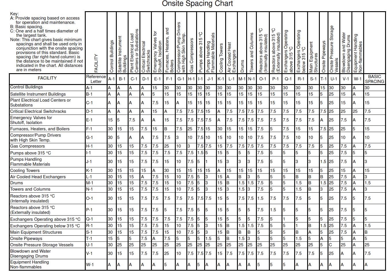
3.3 Minimum clearances shall be in accordance with IRI, HCISS SSD, NFPA 30 and 59A, and API 500
and 2510. See Figure 1 for spacing distances between equipment and facilities. Reduction in the spacing distances shall require provision of additional safety features, for example fireproofing, automatic water spray systems, emergency shutdown facilities and additional fire fighting equipment.
3.4 Plants shall be equipped with an independent main control room. Secondary control rooms may also be installed to operate and monitor certain sections of the plant, if it is convenient for operation.
3.5 Adequate access and area both at ground level and on platforms shall be provided for removal of, for example, catalyst, packing, internal heat transfer coils, mechanical agitators and large PSV’s. The use of overhead hoist and, if justified, overhead bridge crane shall be considered.
3.6 Dosing units, truck loading and unloading facilities and chemical storage buildings shall be located near roads, for easy access. Loading and unloading facilities handling flammable commodities shall be kept a minimum of 61 m from process equipment, and 76 m from tankage.
3.7 Eye wash and emergency showers shall be provided in areas where operating personnel are subject to hazardous sprays or spills, for example acid and caustic. These items shall be indicated on the flow diagrams (P&IDs) and plot plans. Eye wash shall be provided with a chiller, and water temperature controller.
3.8 Personnel protection, for example insulation and shields, shall be provided on lines and equipment operating above 76 °C, when they constitute a hazard to operators during normal operation. Lines which are infrequently used, for example snuffing steam and relief valve discharges, shall not require insulation.
3.9 Valve and flange shields, if used, shall be noted on the flow diagrams (P&IDs).
3.10 Atmospheric exhausts from steam turbines, combustion gas turbines, and internal combustion engines shall be located in a way that they will not present a hazard to personnel and equipment. They shall be at least 3 m higher than platforms or access points that are within a horizontal distance of 7.5 m.
3.11 Where the turbine or engine is driving a compressor or pump handling flammable fluid, the pump area shall not be enclosed and shall be freely ventilated. The exhaust stack shall be covered by insulation and an outer jacketing impervious to liquids.
3.12 Site elevations shall be in accordance with project design drawings and SES C04-E01.
3.13 Elevations of finished top of foundations shall be in accordance with project design drawings and SES B52-E01.
3.14 Minimum requirement for head room clearance shall be in accordance with Table I.
3.15 Clearances around equipment shall be in accordance with Table II.
3.16 Plant layout, spacing and clearances shall conform to the applicable sections of OSHA.
4. Arrangement
Relative positions of units, location of equipment and routing of pipe shall be based on safety, economics, and ease of maintenance and operation. The alignment of equipment, and routing of pipe, shall be consistent with existing facilities, and shall offer an organized appearance.
4.1 Onsite Piping Layout
- Pipe alleys shall be in plant North/South and East/West directions.
- Piping shall conform to plant clearances above floor and grade. Minimum requirements for headroom clearance shall be as stated in Table I below.
- Major process and utility lines shall usually be carried on overhead pipeways. In certain instances, they may be buried, with Company approval, provided they are adequately protected. Lines which will be run below grade, and which will be periodically inspected or replaced, shall be identified on the flow diagrams. Cooling water shall usually be routed above ground.
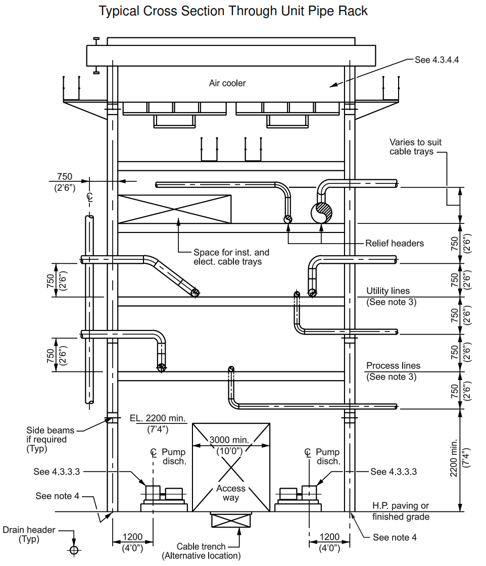
- New pipeways shall be designed to provide space for future piping. The amount of space shall be 25 percent for unit pipeways and 30 percent for offsite pipeways. In cases where plot area does not allow space for future, pipeway shall be designed for addition of a future deck, see Figure 3 below.
- The addition of piping to existing pipeways shall be designed to maximize the utilization of the pipeway. The minimum spacing of lines shall be as shown in Figure 2 below.
4.2 Offsite Piping Layout
Piping shall normally be routed on pipeways and sleeperways. Elevations shall be staggered to permit ease of crossing or changes of direction at intersections. Flat turns may be used when entire sleeperways change direction. The elevations of intersecting pipeways shall be at different levels to allow for future piping, subject to the requirements in 4.1.4. The minimum spacing of lines supported on sleeperways or pipeways shall be as shown in Figure 2 below.
FIGURE 2: Pipe Spacing Chart
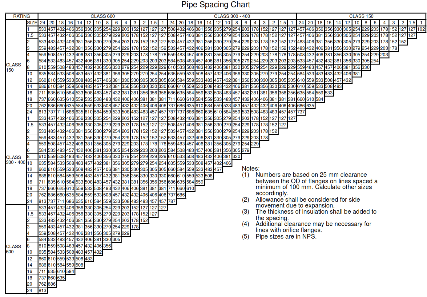
Above grade plant piping between plant equipment, or between separate units within a plant area, shall be projected within pipeway boundaries indicated on plot plans and piping plans. The plot plans and piping plans shall be laid out in a way that they shall provide the necessary access to all areas for operation and maintenance.
4.3 Equipment Layout
4.3.1 The layout of equipment shall permit easy access for operation, maintenance, inspection and cleaning. New process equipment shall be located outside the heat intensity circle of flare stacks. The layout requirements of some of the typical rotating, stationary, and miscellaneous facilities at Company plants is included below and in Figure 1.
FIGURE 1: Onsite Spacing Chart
4.3.2 Compressors
4.3.2.1 Reciprocating Compressors
a. Suction and discharge lines which are subject to vibration (mechanical and acoustic) should normally be routed at grade and held down at points established by analysis of the system.
b. Accessibility and maintenance for large lifts, for example cylinder removal and motor rotor removal, shall be by mobile equipment.
c. Reciprocating compressors may have a partial platform for access to cylinder valves.
4.3.2.2 Centrifugal Compressors
a. Top suction and discharge lines shall be routed to provide clearance for overhead maintenance requirements, or be made up with removable spool pieces. Where possible, large compressor trains shall be located in a way that the working platforms can be interconnected. Units with overhead cranes shall have maintenance drop areas sized to enable maneuvering of heavy-duty trailers loaded with the heaviest removable components of machines.
b. Centrifugal compressors shall have full platforming at operating level.
4.3.3 Pumps
4.3.3.1 Pumps should be located close to equipment from which they take suction. Piping shall be designed to provide clearance for pump or driver removal, and on end suction pumps, to permit removal of suction cover and pump impeller while the suction and discharge valves are in place.
4.3.3.2 Suction lines shall be arranged to minimize offsets. They shall be short, as direct as possible, and non-pocketed from the equipment to the pump. Suction lines routed on sleeperways may rise to pump suction nozzle elevation, subject to Company approval. When reducers are required, they shall be eccentric reducers. Eccentric reducers, if used, shall be oriented in a top flat position. Valve handwheels or handles shall be oriented, whenever practical, to be contained within the perimeter of the pump foundation. They shall be readily operable from grade.
4.3.3.3 Pumps in hydrocarbon services operating at temperatures above their flash point shall not be
installed beneath platforms, structures, or pipeways without Company approval. Sufficient area shall be left around pump and machinery for maintenance and operation accessibility. Rotating equipment shall also be laid out for convenient access for mobile equipment and cranes, see Figure 3.
4.3.4 Exchangers, Air Coolers, Fired Heaters and Reboilers
4.3.4.1 Exchangers shall be grouped together wherever possible. Shell and tube exchangers shall be
stacked as follows:
| 1.2 m in diameter | Stacked three high |
| 1.2 to 1.8 m in diameter | Stacked two high |
| Over 1.8 m in diameter | Shall not be stacked |
4.3.4.2 Channel end and shell covers shall be kept clear of piping and structural members, to allow
unbolting of exchanger flanges and removal of heads and tube bundles. Heat exchangers shall be located in a way that heads and tube bundles are accessible from unit roads.
4.3.4.3 Equipment, for example drums, heat exchangers, pumps and other machinery shall not be located under pipe racks.
4.3.4.4 Air coolers shall preferably be located above pipeways/pipe racks. If the space above pipe racks is not sufficient for installing air coolers, the space above steel structures may be used. Access to the air coolers shall be provided, for operation and maintenance. This shall include appropriate platforms, walkways and handrails, see Figure 3.
4.3.4.5 Fired equipment shall, if practical, be located to prevent flammable gases from hydrocarbon and other processing areas from being blown into the open flames by prevailing winds. Fired heaters shall be located upwind or crosswind of process facilities, and shall preferably be lined up along the primary roads for easy maintenance and safety. Sufficient space shall be provided around fired heaters for mobile equipment handling.
4.3.4.6 Snuffing steam manifolds and fuel gas shutoff valves shall be located a minimum of 15.24 m horizontally from the heaters they protect. Burner valving heater stacks shall terminate a minimum of 4.6 m above platforms within a radius of 12.2 m. Floor fired furnaces, burner valves shall be located near the burner and be operable from grade. For side fired furnaces, firing valves shall be located in a way that they are operable while viewing the flame from the observation door.
4.3.4.7 Pressure relief doors and tube access doors shall be free from obstructions. Pressure relief doors shall be oriented to not blow into adjacent equipment.
4.3.4.8 Reboilers shall be located as close as possible to the equipment they serve.
4.3.5 Vessels and Columns
4.3.5.1 Piping at columns shall be located, when possible, radially about the column, on the pipeway side. Manways and platforms shall be located on the access side. Manways shall be on or about a common centerline. Towers and columns shall be located in a way that all working platforms and manholes face the access road and can be fitted with a conveniently located winch and lift basket arrangement.
4.3.5.2 Platforms shall be provided at manways and nozzles above 4.6 m centerline elevation from high point finished surface (HPFS), unless otherwise approved by SABIC. Platforms shall be positioned in a way that the manhole centerline is not less than 610 mm above the platform, with 760 mm preferred. The bottom of the manhole entry shall not be more than 1.065 m above the platform. Combined platforms shall be furnished, when practical or economical, on lined-up towers with common platform elevations.
4.3.5.3 Vessel davits for handling, for example, internals and relief valves, shall be provided on vessels
exceeding a height of 9.15 m above HPFS, and on vessels not accessible by mobile crane. Davits shall be oriented to allow the lowering of appurtenances into the access area.
4.3.6 Cooling Towers
Cooling towers should preferably be located downwind of buildings and equipment to prevent spray from falling on them. The short side of the tower shall be located into the prevailing summer wind, to obtain maximum efficiency. Cooling towers shall be located a minimum of 15.24 m from process units, utility units, fired equipment, and process equipment. Piping supports shall not be attached to the cooling tower basin walls.
4.3.7 Portable Gas Cylinders
Portable gas cylinders are used in some plant areas for supplying, for example, ammonia, nitrogen, and hydrogen. Their vulnerability to fire exposure shall be considered in selecting their location within the plant.
The following guidelines shall apply:
a. High-risk cylinder installations involving multiple cylinders of flammable or toxic fluids shall be
located at the edge of the plant area, 7.5 m from other hydrocarbon equipment. Good access for fire
fighting shall be provided. Bulk storage of the cylinders shall be in a remote, offsite area.
b. Lower-risk installations of single cylinders containing flammable material, or multiple cylinders of
inert gases, shall be located at least 7.5 m from high fire risk equipment, for example pumps, gas
compressors, furnaces, and equipment operating over 315 °C. In all instances, cylinders shall be
adequately chained or supported to avoid the possibility of falling or being knocked over.
4.3.8 Valves
4.3.8.1 Operating valves requiring attention, observation or adjustment during normal plant operation shall be located within reach from grade, platform or permanent ladder. These valves shall be identified on the flow diagrams (P&IDs) as ‘O.V.’ (Operating Valve) with the exception of control manifold block and bypass valves, and pump suction and discharge valves.
4.3.8.2 Use of chain operated valves shall require prior Company approval. When allowed, chain-operators shall only be used on valves where the bottom of handwheel is over 2.1 m above HPSF, or operating platform. Where practical, valves shall be kept to a maximum of 2.0 m to bottom of handwheel, to minimize the use of chain-operators.
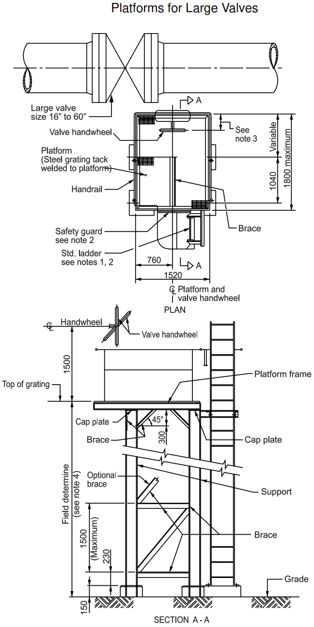
4.3.8.3 The centerline of handwheel or handles on block valves used for shutdown or infrequent maintenance only, located less than 4.5 m above HPFS, and those located in pipeways, shall be accessible by portable ladder. Location of valves in pipeways shall require Company approval. The centerline of handwheel or handles on block valves used for shutdown or infrequent maintenance only, located over 4.6 m above HPFS, shall be operable from a permanent ladder or platform, see Figure 4.
4.3.8.4 Valve handwheels, handles, and stems should be kept out of operating aisles. Where this is not practical, the valve shall be elevated to 2.0 m clear from HPFS to bottom of handwheel. Where practical, ‘lock open’ valves shall have stems in the horizontal position.
4.3.8.5 Relief valves shall be easily accessible. Wherever feasible, they should be located at platforms. Accessibility of relief valves with an elevation over 4.5 m above HPFS shall be as follows:
a. NPS 2 and smaller inlet – accessible from platform, or permanent ladder.
b. NPS 2 1/2 and larger inlet – accessible from platform.
c. Relief valves in pipeways – check with SABIC for accessibility requirements.
4.3.8.6 Relief valves other than for gas shall be installed in a vertical position. Relief valves discharging to a closed system shall be installed higher than the collection header. There shall be no pockets in the discharge line. Relief valves discharging to atmosphere shall have tail pipes extended to a minimum of 2.5 m above the nearest operating platform within a radius of 7.6 m.
4.3.9 Pipe Supports
4.3.9.1 Pipeway routing will be shown on the plot plans. Pockets and dead-ends shall not be permitted in any service. Overhead piping with supports beneath the pipe shall be preferred to that with hanger-type supports. Consistent elevations for all north-south pipeways shall be maintained. East-west pipeways shall be maintained at consistent elevations, but not at the same elevation as the north-south pipeways. Flat turns shall be avoided, except in very special cases and with Company approval. Utility headers shall be placed on the top deck of pipeways wherever possible. The minimum size of process and utility lines on piperack shall usually be NPS 2.
4.3.9.2 The minimum pipe spacing in pipeways shall be as shown in Figure 2. Additional clearances shall be provided as required, for lines that move because of expansion or contraction. Whenever possible, orifice flanges shall be put on the outside edge of the pipeway. If this is not possible, each run shall be considered individually, to ensure proper clearance for instrument piping and maintenance. Ample space shall be allowed for routing of instrument lines and electrical conduit along with the utility and process piping. Lines shall not be located on a pipe support beam directly over a pipe support column; this space shall be left open for the extension of columns required for a future deck. See Figure 3.
FIGURE 3: Typical Cross Section Through Unit Pipe Rack
4.3.9.3 Piping sections requiring frequent dismantling for maintenance, for example for the installation of blanks, shall be provided with permanent supports for the dismantled conditions.
4.3.9.4 The bottom of lines supported on concrete sleepers shall not be kept less than 330 mm above grade. Lines from tankage, reciprocating compressors, and lines paralleling horizontal exchangers and vessels where walkways are not obstructed, may be run on concrete sleepers.
4.3.10 Ladders and Safety Cages
- Access to elevated platforms shall be by permanent ladder. The need for stairways shall be determined, based on platform elevation; number of points requiring attention, observation and adjustment and the frequency of such requirements. Stairways at structures shall be indicated on the plot plan, see Figure 4.
- Safety cages shall be provided for ladders, in accordance with SES B04-F01.
- Ladder safety devices, for example safety belts and harnesses, may be used on boiler and flare
- stack ladders over 6.1 m, in unbroken lengths, instead of cage protection and landing platforms, with Company approval.
5. Plant Roads and Exits
- There shall be a 15 m clear zone between the security fence (the perimeter fence) and the edge of the perimeter road in accordance with HCISS SSD. This clear zone shall be defined as unobstructed flat soil, where crossing pipeline shall be buried. This clear zone of 15 m shall also be provided on each side of the internal fence between plant area and the administration areas.
- Primary roads, secondary roads, and tertiary roads shall be provided around each plant, in accordance with SES C04-E01.
TABLE I – Headroom and Overhead Clearances:
Minimum headroom clearance shall be as follows:
| 1) Headroom over elevated platforms, walkways, working areas and stairways. | 2.2m |
| 2) Headroom over walkways, passageways and working areas at grade. | 2.2m |
| 3) Overhead clearance over roads (from crown) (a) For primary roads in complex. (b) For secondary roads (where major maintenance vehicles are expected to pass) . |
7 m 5.5 m |
| 4) For tertiary roads and pump roads. | 3.5 m |
| 5) Overhead clearance over working areas at grade for mobile lifting equipment access. | 3.5 m |
| 6) Overhead clearance for main process pipe rack from paving surface to bottom of pipe rack beams. | 3.5 m |
| 7) Overhead clearance for pipe rack above road crown to bottom of pipe rack beams. (a) For primary roads in complex. (b) For secondary roads (where major maintenance vehicles are expected to pass) . |
7.0 m 5.5m |
TABLE II – Clearance Around Equipment:
1. Minimum requirement for open space around equipment or clearance between equipment upon final installation shall be as follows:
| HEAT EXCHANGERS | |
| Between horizontal exchanger’s shell flanges
(including insulation) | 450 mm |
| For shell cover end | 1,800 mm |
| For channel end (removable and fixed tube bundle type, and for in situ hydroblast cleaning) | Tube bundle length plus 1,500 mm (not more than 1/3 width of the adjacent road can be used for this purpose) |
| PUMPS | |
| Between pumps of less than 3.7 kW (pumps on a common foundation) | 300 mm
(between pump beds) |
| Between pumps of less than 3.7 kW (pumps on individual foundations) | 750 mm
(between pump foundations) |
| Between pumps of more than 3.7 kW (between foundations) | 900 mm |
| Between pump foundation and obstruction | 750 mm |
| COMPRESSORS | |
| Between compressors | 2,400 mm between compressor foundations |
| COLUMNS | 1,500 mm between foundations |
| DRUMS | 750 mm between foundations |
| SMALL EQUIPMENT ON A COMMON FOUNDATION | 500 mm between equipment |
2. Minimum requirements for spacing around tanks storing inflammable or combustible liquid shall be based on HCISS SSD 27 and NFPA 30 guidelines, and shall include:
a. Tanks spacing: the minimum tank spacing from shell to shell shall be equal to one third of the sum of the two tanks’ diameters, or as specified in NFPA 30
b. Hot oil tanks above 120 °C storage temperature: minimum spacing from shell to shell shall be equal to 1.5 diameters of the largest tank
Notes:
(1) Clearances and levels of pipelines are typical only. See plot plans for actual levels.
(2) Dimensions are in millimeters. Dimensions in brackets are in feet and inches.
(3) This is preferred location but may not be possible due to process requirements.
(4) For foundation details see Figure 4, section A-A.
FIGURE 4: Platforms for Large Valves
Notes:
(1) Ladder serving platform shall be side-step.
(2) Ladder serving platform 1.2 m or more above grade shall be equipped with a safety guard.
(3) The valve handwheel shall preferably lie a minimum of 50 mm inside the platform railing. If this is not possible, the handwheel shall be located no further than 150 mm outside the railing.
(4) Maximum allowable height shall be limited to 4.5 m. Above this, a detailed engineering analysis shall be required.
(5) All dimensions are in millimeters unless noted otherwise.