1.0 PURPOSE.
2.0 SCOPE.
3.0 APPLICABLE DOCUMENTS.
4.0 RESPONSIBILITY.
5.0 MANPOWER.
6.0 TOOLS & EQUIPMENT.
7.0 DE-PURGING OR RELEASING.
8.0 METHODS/PROCEDURES.
9.0 QUALITY CONTROL.
10.0 SAFETY PRECAUTION.
11.0 ATTACHMENTS.
1.0 PURPOSE:
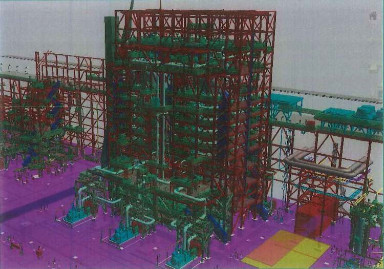
This method statement shall provide minimum Guidelines for installation of Adsorbent Tower Internals & Sieve Loading for Plants and Refinery Projects in accordance with Project Drawings and Project Specifications.
2.0 SCOPE:
This specification covers the minimum requirements for installation of adsorbent tower internals and sieve loading to be applied at Plants and Refinery Projects.
3.0 APPLICABLE DOCUMENTS:
3.1 ARAMCO Project Specifications and Standard.
3.1.1 SAEP-302 Instruction for obtaining a waiver of a mandatory Saudi ARAMCO Engineering requirement.
3.1.2 SAES-H-101V Approved Saudi Aramco Data Sheets-Paint and Coatings.
3.1.3 SAES-L-350 Construction of Plant piping.
3.1.4 Related Vendors Installation and maintenance manuals/procedure and /or specifications.
3.2 Industry Codes and Standards:
3.2.1 AWS D1.1 Structural Welding Codes.
3.3 Inspection and Testing Plan
3.3.1 SATIP-D-001-01 Typical Inspection Plan Pressure Vessel Installation.
3.3.2 SAIC-D-2001 Review of Vessel Safety Instruction Sheet & Procedure for Vessel Internal Component Installation.
3.3.3 SAIC-D-2003 Receiving Inspection of Pressure Vessels- Internal.
3.3.4 SATR-D-2003 Vessel Closure Inspection Certificate.
3.3.5 SATR-D-2004 Tray Test Report.
3.3.6 SAIC-D-2009 Installation & Inspection of Trays & Packing in Vessels (Special Construction Process Procedure).
3.3.7 S-000-3151-003 Specifications for Tray Work.
3.4 Latest Revision of the following Documents shall be used.
3.4.1 Vendor Drawings.
3.4.2 Structural Drawings.
3.4.3 Equipment Details.
3.5 Saudi ARAMCO Safety, Health and Environmental Standard:
3.5.1 Construction safety manual – compliance with schedule D.
3.5.2 General Instructions (G.l’s) at the work site.
4.0 RESPONSIBILITY:
4.1 Construction Manager is responsible for implementing HSE, study, analyze and schedule all construction activities with his department to include manpower and equipment line up as well as other possible resources required for the successful implementation of the construction work activities. Study all aspects of work procedure as per DEC/JGC technical Scope of Work and Saudi Aramco Standard.
4.2 Mechanical Supervisor shall study and review all necessary documents for the application activity in his area to include, technical scope of work, specification, bill of quantities, planned milestone dates and construction procedure in support to his Mechanical Foreman. He shall monitor the availability of materials in accordance with the schedules and construction analysis. He shall be directly reporting to the Construction Manager. He shall coordinate with other discipline to visualize possible conflicts in the drawings as well as in the schedules to provide other options in preventing unnecessary delays and obstructions.
4.3 Mechanical Foreman shall be responsible for the direct work supervision at site and ensure that the work is performed in accordance with DEC/JGC Technical Scope of Work, Saudi Aramco Standard and latest approved for construction drawings. He shall monitor the availability of materials in line with his required schedule.
4.4 QC Inspector shall be responsible in monitoring and inspection of the work and ensured that the work is performed and properly documented in accordance with DEC/JGC Technical Scope of Work and Saudi Aramco Standard.
4.5 Safety Officer/Supervisor shall be responsible in monitoring safety aspects and ensuring that the work is done in accordance with Safety Standard Procedure and Saudi Aramco Construction Safety Manual. He shall discuss to the workers the characteristics of related materials and Status of work area giving reminders as an additional point to work safely.
5.0 MANPOWER
5.1 The Mechanical Supervisor shall control the overall activity on installation of adsorbent internals. The basic manpower under him shall consist but not limited to the following:
5.1.1 Foreman Mechanical
5.1.2 Mechanical Fitters
5.1.3 Electrician
5.1.4 Welders
5.1.5 Watchmen Vessel / Attendant/Firewatcher
5.1.6 Crane operator/ Forklift Operator
5.1.7 Rigger
5.1.8 Helpers
5.1.9 Scaffolder (by others)
5.2 Safety Officer.
5.3 QC Inspector.
6.0 TOOLS AND EQUIPMENT;
6.1 Tools and equipment needed should be in good condition and must be checked by Mechanical Supervisor/Safety Officer prior to use in the construction area. These Includes but not limited to:
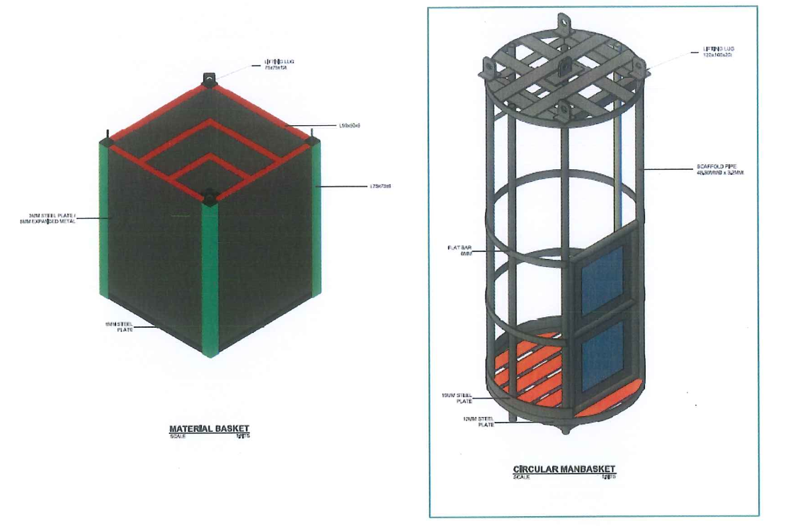
- Material Basket and Circular type Man basket.
- Removable safety ladder.
- Circular trolley with cable hoist.
- Chain blocks, snatch blocks.
- Portable Lighting and flashlights for internal detail inspection (Low-voltage incandescent 220V down to 12V).
- Chalk or Paint stick.
- Spirit Level.
- Special Laser (Vendor Axens to provide).
- Portable air analyzer with alarm device.
- Portable moisture and temperature analyzer.
- Bravo / Radio for communication.
- Vacuum cleaner (5HP heavy Duty).
- Very efficient dust mask and Air Mask.
- Catapac Machine (Vendor Axens to provide).
- Welding Machine.
- Sieve leveling scrappers made of aluminum.
- Metal spacer and screw clamp (by panel supplier).
- Receiving hopper.
- Weighing Balance 0-1100kg accuracy 1 kg.
- Scale 0-400kg, accuracy 1 kg.
- Dry air and oil free air compressor 750CFM with manifold to supply ventilation of adsorbers (Min flow 5Nm3/min, dew point -10°C) and to drive the Catapac (Min. flow 1 Nm3/min, ?bar) complete with hoses.
- Dry and oil free air compressor 750CFM (back-up compressor)
- Top platform shelter
- Top scaffold loading bay
- Receiving hopper(s) with 6 slide valve on top of adsorbers for sieve loading
- Catapac Support
- Shelters for sieve, panel, permanent material, internal piping and temporary material shelters.
- 40ft sieve storage container and 40 ft site office
- Liter clean steel or plastic drum for temporary storage of unused sieve
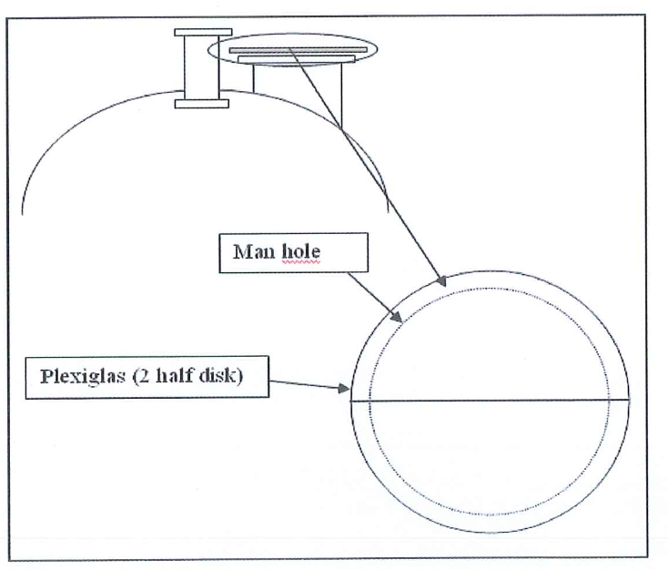
- Plexiglass cover for covering the top manhole while bed loading
- Plywood working boards
- Plastic 1 liter sampling battles
- 20liter buckets
- Hydrotest Tools and machines
- Nylon slings
- Exhaust and ventilation Fan
- Lighting system for shelters
- Crawler & Mobile Crane
- Torque Wrenches & Pneumatic tools
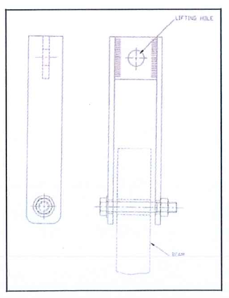
- Beam lifting device
- Tool, Sack bag, Rope and ginney wheels
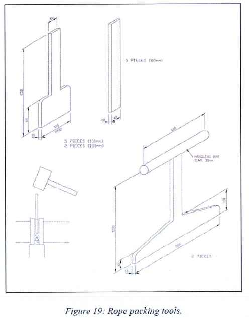
- Rope Packing tool (by tray supplier)
- Gap gauges and feeler gauges
- Ladder I Rope Ladder
- Forklift
- Dedicated very clean soft rubber sole shoes
- Gloves and tight overall
- Steel trestle.
- Center Pipe centering temporary beams.
7.0 De-purging or Releasing.
7.1 Secure work permit before nitrogen releasing/de-purging activities.
7.2 Release of nitrogen must be well informed to all nearby workers.
8.0 METHODS/ PROCEDURES:
8.1 Jobsite Receiving and Inspection:
8.1.1 Upon withdrawal and receipt of materials from warehouse, receiving inspection shall be conducted immediately.
8.1.2 Record of inspection shall be documented as per applicable SAIC (Material Receiving Inspection); findings and deviations shall be documented in Quality control Inspection Report (QCIR) and Non Conformance Report (NCR).
8.1.3 Haul material as needed to site as per installation schedule/sequence.
8.1.4 Protect all materials for sand and rain
8.2 Preparatory Works
8.2.1 Secure all the valid documents such as confined space permit prior to work commence.
8.2.2 Tools and equipment shall be made operational and available for use. Ensure tools are color-coded accordingly
8.2.3 Mobilize all manpower, tools and equipment needed for the job.
8.2.4 Manpower who will do the job should secure training on confine space and necessary training to do the job at Daewoo.
8.2.5 Install barricades to confine the area for authorized personnel only.
8.2.6 Install scaffold as required.
8.2.7 Shuttle or circular manbasket must be provided.
8.2.8 Provide monorail beam for loading and unloading of internals.
8.2.9 Enough power lighting for the outside of the adsorbers.
8.2.10 Power plugs shall be available.
8.2.11 Dry and oil free air to ventilate the adsorbers (minimum flow >5 Nm3/mn to get a velocity> 3 cm/s outlet of the top MH, dew point -10°C).This will allow circulating air inside the adsorbers and preventing the possible dusty and humid air from outside to entry the vessels This will prevent as far as possible rust formation on the beams and the shell during the installation.
8.2.12 Provide carbon steel or stainless steel shims of various thickness to adjust the leveling – horizontality of all beams (provided by beams supplier).
8.2.13 Stud and nuts to be provided by the beams supplier.
8.2.14 Designated manways and platforms shall be checked and evaluate for the accessibility condition before installation.
8.2.14.1 After manhole opening, gasket contact faces shall be rust proofed and protected using thin wooden ring plates.
8.2.15 Provide exhaust blowers or ventilation fans on designated manholes of vessel. Lightings shall be sufficiently provided inside the vessel/column tower.
8.2.16 Prior to the start of work, a Confined Space Entry Permit should be secured. A reading of the atmospheric content should also be taken to ensure safe for working and the personnel should have their ID Badges bearing the confined space color coding. A vessel attendant should always be available at the entry/exit points.
8.2.17 A log of all personnel coming in and out of the confined space shall always be available.
8.2.18 Prior to start the lower tray installation inside adsorbers, first inspection of adsorbent tower shall be done.
8.2.18.1 Full secure scaffolding, with platform at each bed levels, and ladder connecting all platforms to be installed (by DEC scaffold sub contractor). Such structure will be needed for inspection of the inside of both adsorbers by AX.ENS. The inspection is performed to check the following:
8.2.18.1.1 All support rings levelness and horizontality,
8.2.18.1.2 All beams support welding and levelness.
8.2.18.1.3 Cleanliness of all annular chambers. To do this it will be necessary to at least open one or two nozzles for each annular chamber, then to close the nozzles again until internals installation work reaches the relevant level.
8.2.18.1.4 Sieve sampling devices proper location,
8.2.18.1.5 All dump or extra nozzles are externally installed with properly rated flanges and gaskets.
8.2.18.1.6 All welding are still proper after transportation and erection of the adsorbers,
8.2.18.1.7 Centering of the Center Pipe,
8.2.18.1.8 There is no rust spot on any part of the adsorbers shell, Center Pipe shell and top and bottom heads.
8.2.18.1.9 The cleanliness of the adsorbers.
8.3 Critical points related to work during tray installation
8.3.1 General
8.3.1.1 The following points have to be checked before panel introduction in the adsorbent towers and once the panel is in position:
8.3.1.2 Line-up of the beam supports on shell and on main beams, for the secondary beams installation.
8.3.1.3 Horizontality and flatness of beams and panels.
8.3.1.4 Horizontality and flatness of each tray checked on several points by a special level measurement.
8.3.1.5 Rocking of all panels.
8.3.1.6 Gaps between the panels themselves and between the panels and the shell and the Center Pipe shall be checked. These gaps shall be such that the provided rope diameter will fit in for tightness.
8.3.1.7 Integrity of screens on both sides concerning the panels of intermediate trays and one side for the Lower Tray and Upper Tray.
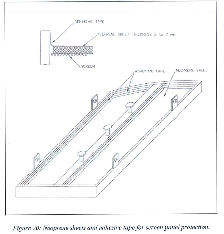
8.3.1.8 To avoid damaging the screens, protective neoprene sheets will remain on the upper side of each panel after installation, until final cleaning and final inspection is done prior the sieve loading. These neoprene protections will be put in place on site during the panels ground inspection.
8.3.1.9 Once on site, the crates (with piping, beams and panels) shall be stored on dunnage and shall be off the ground to be protected from any water/rain accumulation and properly protected with tarpaulins or any other means to protect any rain/water to enter inside the crates.
8.3.1.10 Overall sizes of the vessel and of the internals to be checked on site after erection and during the centering trial of the Center Pipe.
8.3.1.11 Roundness of the vessel to be checked on site after erection and during the centering trial of the center pipe.
8.3.1.12 Roundness, straightness and centering of the center pipe to be checked on site after erection, during the inspection of the adsorbers, prior to start Lower Tray installation.
8.3.1.13 Number, diameter and orientation of the nozzles might be rechecked on site after erection to vertical position.
8.3.1.14 Proper welding of the beams support.
8.3.1.15 Line-up, horizontality and flatness of the tray support rings on the shell and on the center-pipe.
8.3.1.16 Line-up of the beam supports on shell and center-pipe for the main beams.
8.3.1.17 Rocking of all panels is checked. At shop it shall be nil or minimized.
8.3.2 Cleanliness
8.3.2.1 All surfaces (visible or not) of all equipments must be perfectly clean before any assembly: no scales, no particles, no rust, no barbs.
8.3.2.2 Make sure there is no foreign material inside the annular chambers. If any, it shall be removed and perfectly cleaned using vacuum cleaner and special devices provided by vendor.
8.3.2.3 Make sure there is no foreign material inside the pipes.
8.3.2.4 At reception threaded holes in support beams for the upper trays should be plugged with a proper threaded (plastic) stud easily removable. Threading cleanliness and proper machining have to be checked.
8.3.2.5 No rust shall be present inside the adsorbers. Presence of rust leads to an important loss of time when getting rid of it. Potentially on site sand blasting would be required depending of the thickness of the rust layer.
8.3.3 Protection Against Corrosion
8.3.3.1 From the first on site inspection up to final closure, dry air shall always be supplied to the inside of the adsorbers to avoid any humidity inside leading to rust formation.
8.3.3.2 Panels and internal piping must be unpacked gradually just before lifting into the vessel. This is done on site. Potentially, if rust is detected during the unpacking, cleaning will have to be performed and rust preventive will have to be added, prior to start installation work of such rusty panels or piping, inside the adsorbers.
8.3.3.3 Outside and inside work must be stopped in case of rain or heavy fogs or sandstorm, etc. No rain, no water, no sand, no dust is allowed to go inside the adsorbers. In case of slight mist the work could be pursued inside the adsorbers provided a proper shelter is installed on top of the adsorbers to prevent any mist to enter in the adsorbers.
8.3.4 Welding Procedures
8.3.4.1 For any kind of weld inside the vessels, full GTAW is required. In case of any weld to be done or redone on the adsorbers shell or center pipe, the relevant vendor shall be contacted to get its advises on the proper welding procedure in application of mechanical codes and on the non destructive tests to be performed, like MPD (magnetic particles distribution), or any others ND tests.
8.3.4.2 Welding procedures to be defined by contractor and reviewed by AXENS for comments.
8.4 Tolerances
8.4.1 Tolerances concerning the vessels, the panels and the trays once installed are reported in the Process Data Book and shall be confirmed by vendors and all deviation must be submitted to AXENS for approval.
8.5 Requirements
8.5.1 Particular heavy arrangements regarding equipments and site
8.5.1.1 Facilities on site (Adsorbers are erected). All facilities layout and dimensions to be prepared.
8.5.1.1.1 At Ground
8.5.1.1.1.1 Multi-purpose facilities such as:
Road paving is completed. Suitable cranes fitting with specification, shared for sieve operations and panels installation.
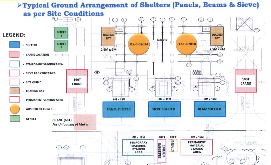
Typically the crane should be capable to lift up to 1200 Kg to ~ 50 meters. To fit with the Catapac apparatus nominal flowrate (15 m3/h), minimum of one sieve big bags every 4 minutes shall feed the receiving hopper.
Duration of the transfer of a big bag from the sieve storage shelter to the receiving hopper should be as short as possible. This includes for each bag.
Prior loading, bags are weighted and stored inside the bags temporary shelter.
Lifting from ground hoist and position the bag above the top hopper.
Emptying In the hopper.
Lifting the empty bag and its removal to a convenient location.
Then being ready for the new bag.
A Crane is used to lift all necessary internals as well as the sieve big bags for loading. The crane must be permanently available to lift the big bags and the main equipment needed for trays installation. The main estimated characteristics of the most important pieces to lift (to be checked with
manufacturers) are:
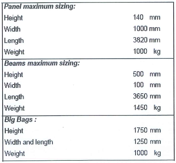
Truck(s) with required lifting device to be able to unload on the unpacking area, panels crates, piping crates, beams crates, sieve containers, etc…. Due to limitation on the possible lifting device of such crates transportation trucks, it might be needed to use either one of the two cranes dedicated to the lifting for internals or sieve, or to use an additional crane when crates unloading is necessary, if the two permanent cranes are already fully used.
The lighting will be such that the crane operator will have no problems during night time to lift any material required (panels, piping, sieve, etc … ).
8.5.1.1.1.2 Facilities related to sieve loading Refer to page 35 to 37 of J12-A-DOC-VE 553759 D1 .doc for details.
8.5.1.1.1.3 Facilities for trays and beams installation Refer to page 38 to 45 of J12-A-DOC-VE-553759 D1 .doc for details.
8.5.1.1.2 At top platform of adsorbers
8.5.1.1.2.1 A working floor binding both adsorbent towers is required at top of the adsorbers. This working area shall be large enough to allow all operations at the top including, Catapac maintenance and protected area for grinding of the internal piping (Upper tray). All necessary space for material storage in coffer or whatever shall be available.
Refer to page 46 to 52 of J12-A-DOC-VE-553759 D1 .doc for details.
8.5.1.1.3 Inside adsorbers
8.5.1.1.3.1 Facilities related to first inspection of adsorbent tower.
Full secure scaffolding (Attachment 2.4), with platform at each bed levels, and ladder connecting all platforms to be installed. (Owner or subcontractors to provide). Such structure will be needed for inspection of the inside of both adsorbers by AXENS, prior to start the Lower Tray installation. This inspection is performed to check:
• All support rings levelness and horizontality • All beams support welding and levelness
• Cleanliness of all annular chambers. To do this it will be necessary to at least open one or two nozzles for each annular chamber, then to close the nozzles again until internals installation work reaches the relevant level.
• Sieve sampling devices proper location.
• That all dump or extra nozzles are externally installed with properly rated flanges and gaskets.
• That all weldings are still proper after transportation and erection of the adsorbers.
• Centering of the Center Pipe.
• There is no rust spot on any part of the adsorbers shell, Center Pipe shell and top and bottom heads.
• The cleanliness of the adsorbers.
8.5.1.1.3.2 Facilities related to sieve loading and CATAPAC.
The top part of the ladder between the center pipe and Catapac platform shall be removable to allow the Catapac trolley to come below the top man way for installation using the top winch. (See figure 14 page 57 of J12-A-DOC VE-553759 D1 .doc for details.
8.5.1.1.3.3 Facilities for transportation material and personnel.
A shuttle (circular man-basket) to lift conveniently and safely 3 or 4 persons, total weight must be within SWL of shuttle (circular man-basket).
Center Pipe.
• A ladder hooked on the center-pipe
• The ladder will be sectioned in several parts (as many parts as beds). Each part will be dismantled following the progress of the bed loading
8.5.1.1.3.4 Facilities for beams and trays installation
Center Pipe
Top head
• A platform supporting the Catapac apparatus with 2 trolleys to move it horizontally and to allow the sieve loading control of the bed. Refer to the AXENS Process Data Book for the full specification of this Catapac platform
• A ladder to access from the edge of the manhole to the Catapac platform.
• A removable safety ladder to access from the Catapac platform to the center pipe ladder.
• A circular trolley with cable hoist. Cable hoist and trolley must be equipped with remote control from the bottom of the
vessel. It is used for panels and beams installation.
o Chain blocks shall be provided to be able to adjust the position of beams or panels to install them. The chain blocks are used at the level where the installation is going on.
Bottom Head
• After total adsorbers inspection is completed at the satisfaction of all parties, then the complete scaffolding is removed except for the bottom head where the following items are kept.
o A temporary scaffolding or floor to allow beams and lower tray panels installation and bottom manifold assembly. The beams, the panels and the pipes will be introduced through the top manhole
o The bottom manhole will be used during this step to allow internal access for personnel, small pieces of material and supplies
8.5.2 Utilities and complementary items to be provided
8.5.2.1 During first inspection
8.5.2.1.1 Powerful lighting shall be available inside the adsorbers right from the moment the scaffolding is being erected
8.5.2.1.2 Chalk or neutral paint sticks to be available.
8.5.2.1.3 Several spirit levels in the size of 0.5 meters to about 2 meters to be provided
8.5.2.1.4 Tape measurement, one short 2 meters, one long ~ 10 meters
8.5.2.1.5 Special laser to allow dimensions measurement. AXENS will have one available. If necessary to get more Owner or subcontractors to provide
8.5.2.1.6 Special laser device to check horizontality of rings, beams, potentially panels, etc… Eventually verticality of the adsorbers as well as of the Center Pipe shall be checked
8.5.2.1.7 Argon and all necessary means for welding as well as performing ND test.
8.5.2.1.8 Magnetic particles distribution instrument shall be available on request, if any welding as to be done or repaired in the shell of the adsorbers
8.5.2.2 At top platform only, during internals installation.
8.5.2.2.1 Enough power lighting for the outside of the adsorbers. In particular the top platform should be lightened to be able to work on night time.
8.5.2.2.2 Normal power plugs shall be available for several tools to be used at the same time. Especially for grinding in the special dedicated area of the top platform and for welding inside the adsorbers during lower tray and upper tray piping installation.
8.5.2.2.3 Four 200 liter very clean steel or plastic drums on a pallet to store temporarily the sieve in excess.
8.5.2.2.4 A metal holder to suspend one of the above mentioned drum if necessary.
8.5.2.2.5 A desk to be provided
8.5.2.2.6 Fresh drinking water to be available on a special dedicated area on the top platform as well as at ground level for all workers. No water is allowed inside the adsorbers as well as inside any shelters or temporary storage containers.
8.5.2.2.7 Plumb line to be able to check the centering of the Center Pipe to be exactly centered with the center of the inlet P/A nozzle at the top of the adsorbers.
8.5.2.2.8 Portable air (02) and CO analyzers with alarm devices should be available at any time to check the minimum oxygen and carbon monoxide content in the vessel (personnel protection) especially during GTAW welding.
8.5.2.2.9 A portable moisture and temperature analyzer shall be available to be sure that the dry air flushing is good enough to avoid any humidity entry inside the adsorbers.
8.5.2.3 Required for work at every floor (including top platform) during internals installation.
8.5.2.3.1 Powerful lighting to be able to safely and easily work at night shall be available.
8.5.2.3.2 Dry and oil free air to ventilate the adsorbers (minimum flow >5 Nm3/mn to get a velocity> 3 cm/s outlet of the top MH, dew point -10°C). This will allow circulating air inside the adsorbers and preventing the possible dusty and humid air from outside to entry the vessels. This will prevent as far as possible rust formation on the beams and the shell during the installation
8.5.2.3.3 A minimum of three pairs of walky talky to be available for communications from inside to outside.
8.5.2.3.4 Power low voltage (Low intensity) for lighting and normal power for tools.
8.5.2.3.4.1 Enough power low voltage (low intensity) plugs shall be available for several lighting inside the adsorbers. They will be used at the same time. The lighting shall be such that there will be no problems for intermediate as well as final inspection. In addition piping shall be well lighted so that the welders can make proper welding
8.5.2.3.4.2 Special dedicated lighting shall be provided for the Catapac platform as well as for loading profile checks
8.5.2.3.5 At least 6 powerful flashlights will be available as well as spare battery to avoid being short in portable lighting.
8.5.2.3.6 At least one pencil type powerful flashlight will be available for inspection of the flexible hoses during final inspection
8.5.2.3.7 At least two portable powerful lighting will be available in both adsorbers, to be able to make a proper inspection in any location of the internals assembly especially for bottom part of piping, annular chamber welding checks, and for checking the proper gasketing.
8.5.2.3.8 At least two very powerful vacuum cleaners will always be available for cleaning the inside of the adsorbers before final cleaning and potentially for intermediate inspection
8.5.2.3.9 Argon and all necessary means for welding as well as ND testing. Should be used for Upper and Lower trays only
8.5.2.3.10 Dry, oil free, air for leak tests (0.5 bar g, dew point -40°C). (Instrument air for instance). Used for Upper and Lower trays
8.5.2.3.11 Potentially dry air for air tools if required
8.5.2.4 For Beams Installation
8.5.2.4.1 Carbon steel or stainless steel shims of various thickness to adjust the leveling – horizontality of all beams. Such shims could be fabricated on site on request or provided by beams supplier
8.5.2.4.2 Shims will be tack welded in place
8.5.2.4.3 Stud and nuts to be provided by the beams supplier
8.5.2.4.4 To check levelness and horizontality. Checking to be done using the same material as during first inspection of the adsorbers
8.5.2.4.5 At least two numbers of the following beams lifting devices or equivalent is required.
8.5.2.4.6 Chain block to be able to put the beam in any required position to be able to install them.
8.5.2.4.7 Threaded holes in the beams will be rechecked for proper threading (No damage and clean). Owner/Subcontractor to provide the threading check devices.
8.5.2.5 For Panels Assembly
- Chain block, the same as used for the beams.
- Crowbars, hammers.
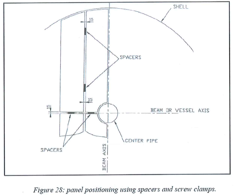
- Metal spacers and screw clamps to maintain the required gap between every panel. Panels supplier to provide proper spacers and screw clamps in such number that at least enough two trays (one on each adsorbers) can be simultaneously assembled.

- Field GTAW welding machines and supplies for upper and lower trays welding operations, as well as to be able to make any necessary repairs at ground level (Panels, piping, etc.)
- Dye penetration check to be provided in enough amount to be able to proceed to dye checking of the welds.
- Enough filler of the proper specifications according to welding procedure which shall have been provided by subcontractor and approved by AXENS, shall be available.
- Argon for GTAW welding to be provided with the proper purity to make a proper GTAW welding.
- In case of screen damage, the screen manufacturer’s representative on site must be involved in the repair.
- Glass fiber rope (from 8 to 30 mm diameter). Trays supplier to provide several diameters as per AXENS recommendations.
- Steel wire rope to be used for Lower Trays installation to avoid glass fiber rope blocking the V3 nozzle.
- Requirements are such as minimum three meters on each side of the V3 nozzle are covered. As the main purpose of this item is the same as rope arrestor, steel wire rope diameter should be determined depending on observed gap once lower tray is installed. Rope packing tools provided by tray supplier.

- Forks, plates, nuts, clamps, washers if needed, to fasten the lower tray. The fork will be either with double nuts or one tack welded nut. Some shims of various thicknesses shall be available for the clamps. (If any shim is used it will be tack welded). Supplier of the panels to provide enough of these items for both adsorbers.
- Studs, nuts, clamps and washers to fasten the upper and the lower trays to beams. Supplier of the panels to provide enough of these items for both adsorbers.
- Flats and angle bars to be welded panel to panel, panel to shell, and panel to Center Pipe on the lower and upper tray. These seal cover plates are provided by tray manufacturer.
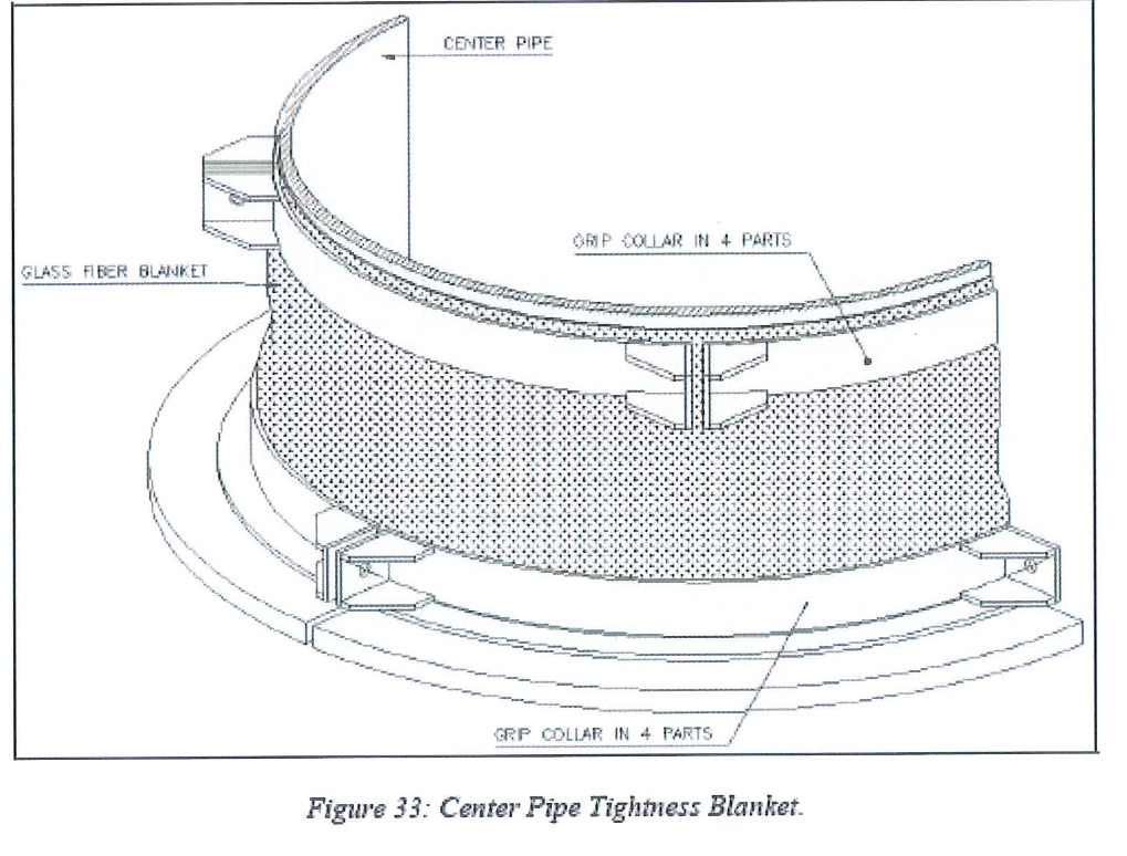
- Center Pipe tightness blanket and associated elements. Provided by tray manufacturer.
- Bolts, nuts, gaskets (temporary one as well as final one) for internal piping flanges. Supplier of the panels to provide enough of these items for both adsorbers and 24 trays. Total numbers per diameters to be checked on site prior to start the internals installation. At least 10 % gaskets spare shall be available.
- Vacuum cleaner (See above for vacuum cleaners used during initial inspection of the adsorbers).
- Special Neoprene protection is required for the panels, during temporary storage, handling and installation. The neoprene sheet thickness is large enough to protect the screen from any damage of falling object (10 mm). At least two complete sets of the neoprene sheets and a spare set are needed.
- The neoprene shall be on one piece and perfectly adjusted to the tray panel geometry. Large and soft but unyielding and easily removable tape shall be provided. It should stitch neither on the neoprene nor the panels frame after removing as resulting cleaning phase may be very time consuming.
- Special gauges to be provided to be able to check the gap between two wires on the panels upper and lower profiled wire screen. These gauges are also used to check the gaps between the screen and the frame of the panels. The gauge feeler is 0.223mm and no-go checking should be performed.


8.5.2.6 For Sieve Loading
- Hoppers installed and equipped as previously specified
- A rigid and transparent plastic cover to install on the manhole during sieve loading.

- This Plexiglas cover will allow the AXENS dense loader to see through, and prevent to get harmful sieve dust outside. It should be easily removable to allow the dense loader to go inside to survey the sieve profile and to check the Catapac good operation.
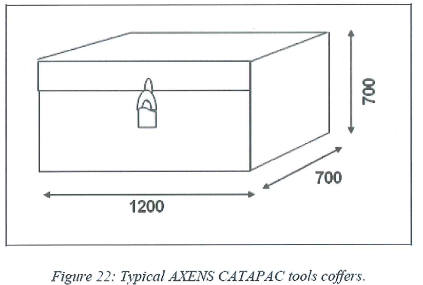
- In order to safely store all the Catapac tools as well as the AXENS material, two metals coffers which can be safely locked will be provided to AXENS

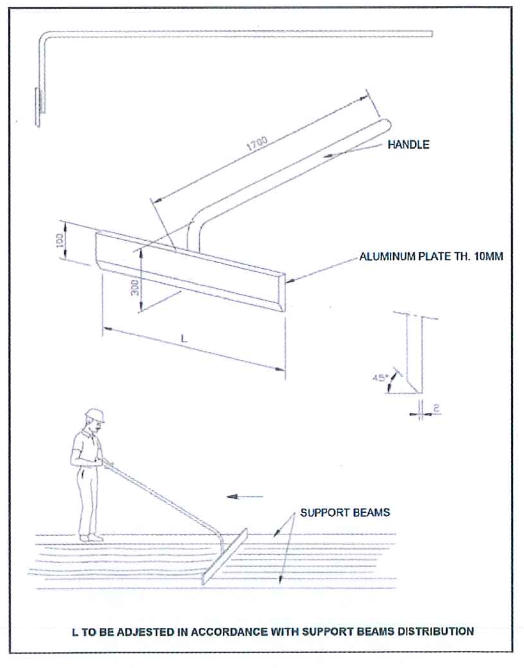
- Sieve leveling scrapers made of aluminum

- Atleast 48 Samples plastic bottles of ~0.5 liters to 1 liter to be available. 2 Plastic bottles are required for sampling of each bed to be loaded. The bottles cover shall be seal tight type.
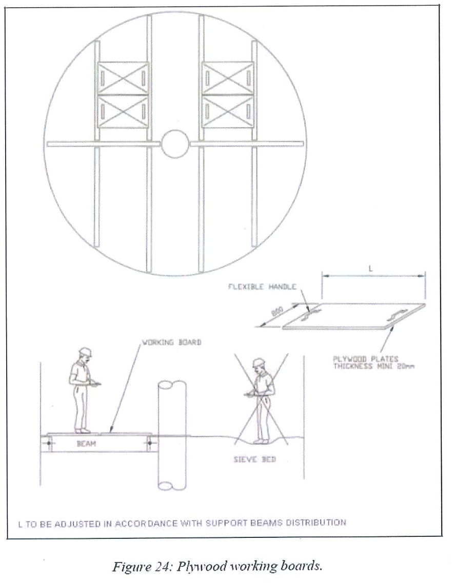
- Several plywood working boards (At least three for each adsorbers) to allow access to bed for panels installation

- Small shovels, Small brooms and 20 liters buckets with handles to remove sieve in excess.
8.5.2.7 Safety
The following safety measures are only the one recommended by AXENS and shall not be considered as exhaustive list.
8.5.2.7.1 At top platform
-
- Safety life line and harness to be available and attached close to the top manhole. This life line is mainly used by AXENS Catapac operator while he stops the machine to cross check loading profiles (There is no more protection as the Catapac is in loading position).
- A guardrail could be foreseen around the top manhole to prevent any casual fall especially if the top of this MH is very close to the platform level.
- A closed wardrobe to store the safety equipment.
- Harnesses, lifelines, to be provided for the personnel working inside.
8.5.2.7.2 Inside the adsorbers
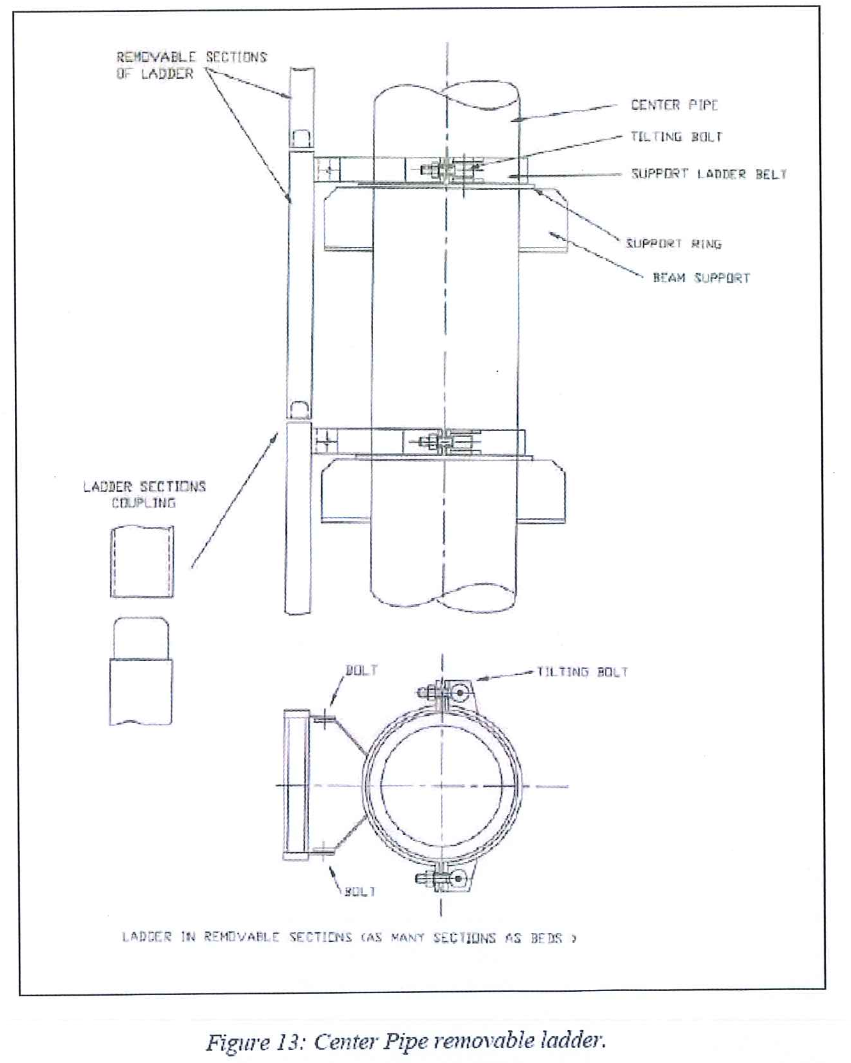
- The temporary removable ladder on the Center Pipe (Figure 10) will be used in case of emergency. During sieve loading and trays installation, due to the dust accumulated during the loading on the temporary Center Pipe ladder, the ladder is used only in case of absolute necessity.
- In addition to the temporary ladder on the Center Pipe AXENS recommends that in case of emergency of any kind, including personnel, the baskets (see figure 9) shall be always available on the top platform to be able to evacuate the personnel from inside the adsorbers .
- In case of power failure, an emergency alternate source of Power might be provided to be able to operate the top platform hoists.
- Harnesses, lifelines, to be provided and work by the personnel working inside..
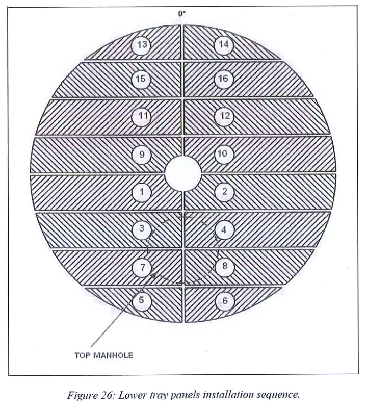
8.6 Lower tray installation sequence
8.6.1 Prerequisites
8.6.1.1 Prior to install lower tray Adsorbent tower, center pipe and annular
chambers inspections relative to dimensional and cleanliness aspects
are successfully achieved.
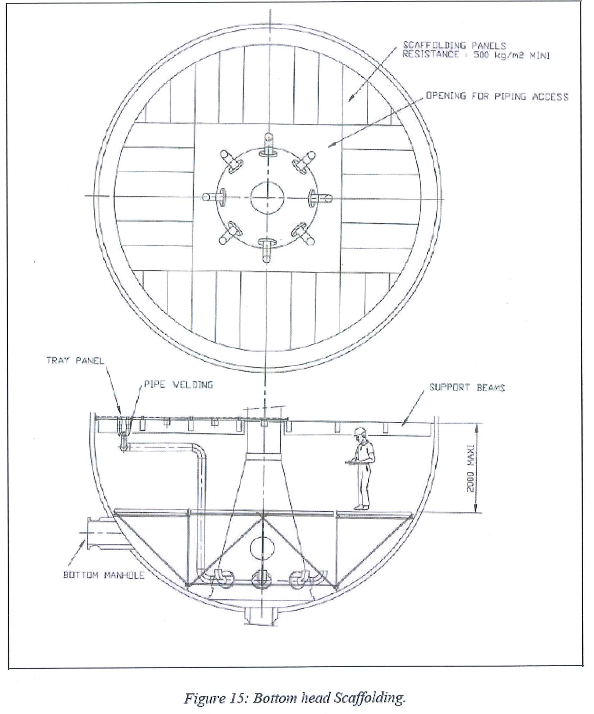
8.6.1.2 Adsorber first inspection scaffolding has been dismantled and only
bottom head platform (refer to fig 15 on page 59 of AXEN vendor
procedure) is remaining in place.
8.6.2 Lower tray beams installation
8.6.2.1 Prepare at ground the beams of the tray.
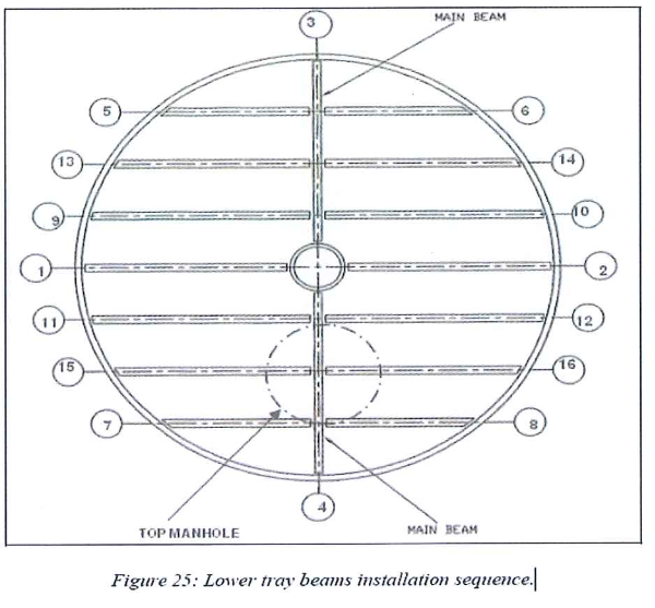
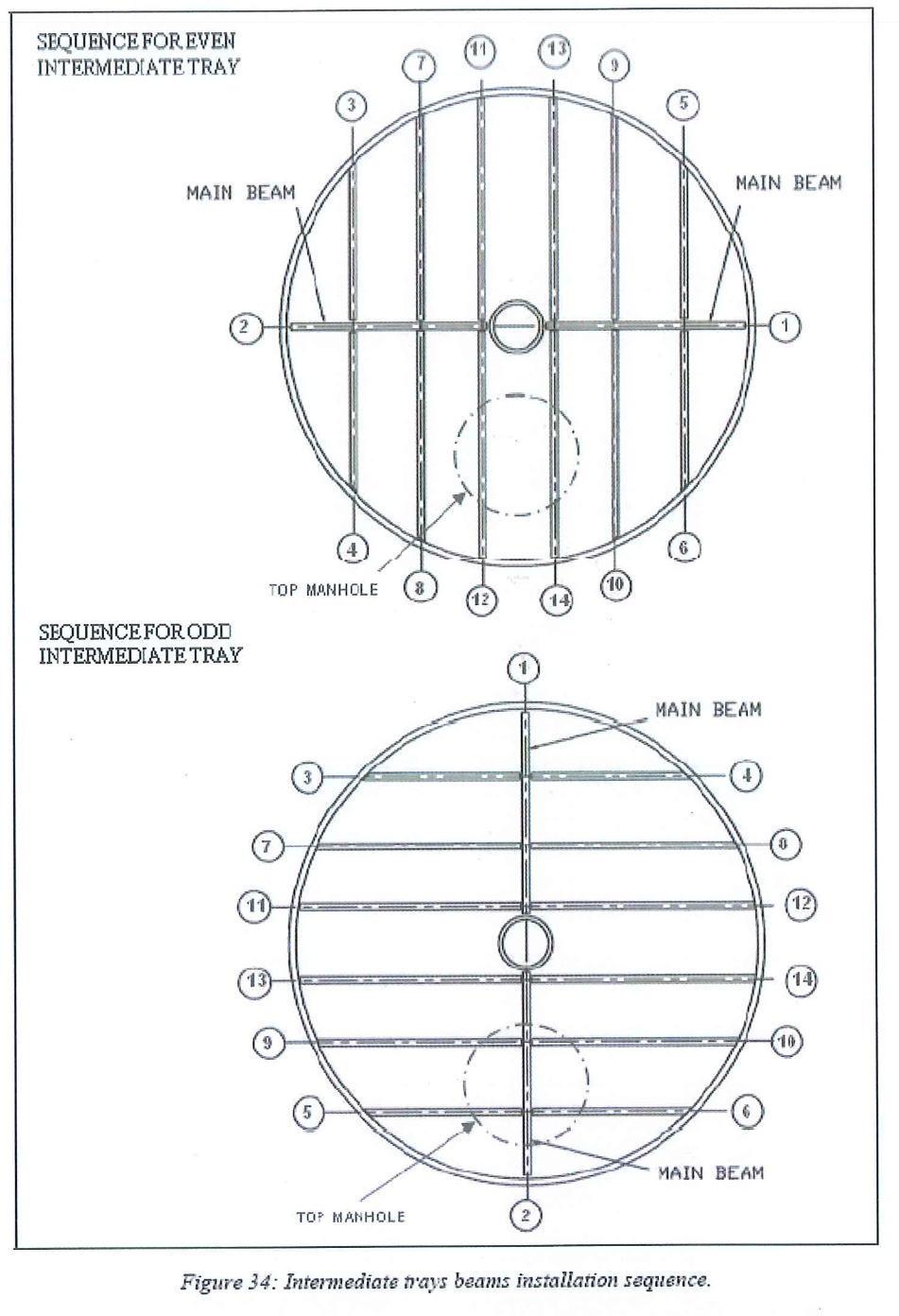
8.6.2.2 Install the beams beginning by the 2 main ones.
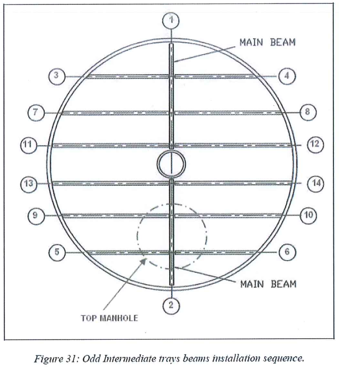
8.6.2.3 Then continue installation following the typical beams installation sequence.
8.6.2.4 Adjust the leveling of the beams using the various thickness shims. Adjust the relative position between beams.
8.6.2.5 Bolt the beams to the different supports.
8.6.2.6 Check the fastening, horizontality and the flatness of the beams.
8.6.2.7 Tack weld all potential moving parts: bolts, shim plates.
8.6.2.8 Punch mark the beams once the complete set is in position.
8.6.3 Lower tray panel installation
- Support rings and top faces of beams must be clean.
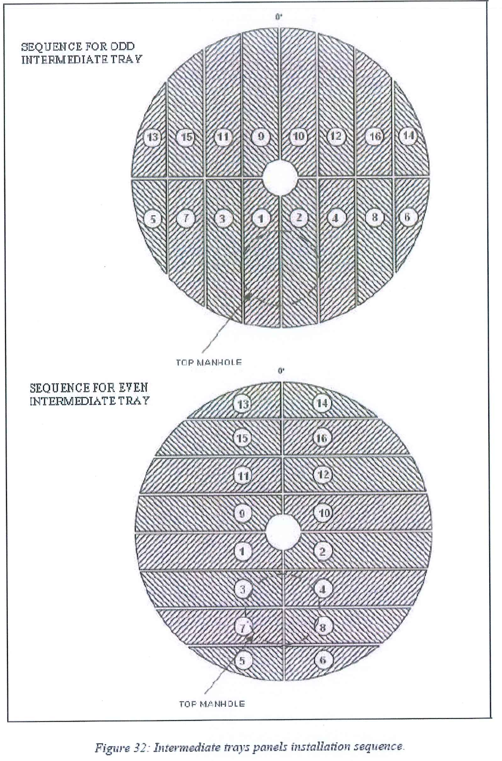
- Panels can be installed inside the vessel following the typical panel installation sequence.

- 8.6.3.3 Install the first panel
8.6.3.4 Adjust the position of the first panel to equalize the distance between panel frame and beams axis on each side. 
- Adjust panel to panel clearance using 15 mm thickness spacers. Shift panel with crowbars and block them with screw clamps Remaining space will be packed on the periphery.


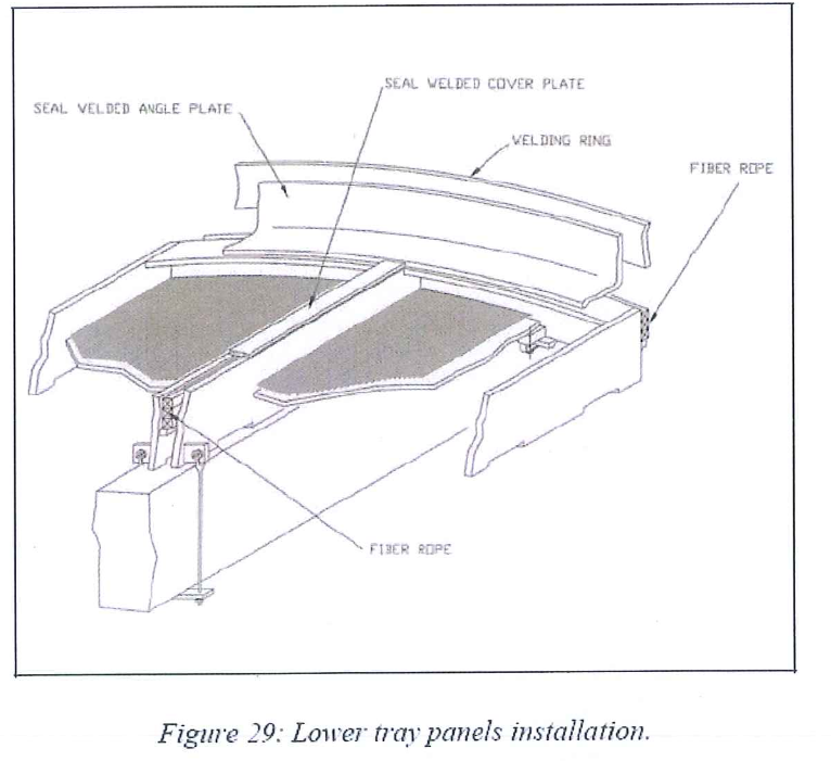
8.6.4 Bolting and tightness procedure for lower tray
- Fasten the fork joints and the split pins to the plates located on the
lower side of the panels. Install the panel to panel plates under the
beam. - Install the clamps fastening the round edge side of the panel to the
support ring. - Screw the nuts symmetrically in order to balance the strains (first
panel to panel staples, then panel to support ring clamps). - Check the horizontality and the flatness of the tray.
- Install the metallic wire rope and alternate rows of glass fiber rope. Packing to be performed according to the dedicated AXENS procedure.
- Install and GTAW weld the seal plates on the panels.
- GTAW weld the seal angle plates on the welding rings of the shell and center pipe and the tack welded plates of the round edge of the panel.
- To prevent warping of the panels by localized hot points, an alternating welding scheme must be followed. This scheme will be provided by the contractor in charge of internal assembly and submitted to AXENS’s approval.
8.6.5 Lower piping manifold installation
- Check the internal and external surfaces of the piping. In case of rust, piping must be brushed before introduction into the vessel.
- Install the piping by using GTAW process.
- Connect the flushing line to the bottom of the center pipe.
- After completion, visual inspection of the welding and a dye check are to be performed.
8.6.6 Lower tray and piping manifold leak test
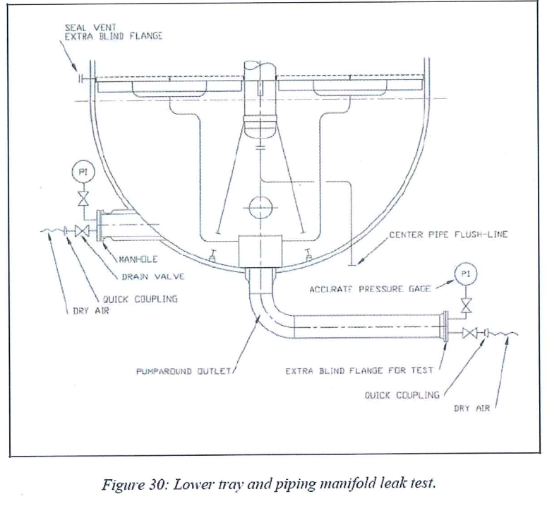
8.6.6.1 Mechanical resistance
- During this step no entry inside the vessel is permitted
- Check the equilibrium device nozzle is blind.
- Install a temporary blind flange on the pump around outlet.
- Close the manhole and all the other nozzles located on the bottom head.
- Pressurize bottom head under dry air at 0.3 bar g. maintain 2 hours.
- Depressurize the bottom head.
- Verify visually the mechanical integrity of the different pieces of the tray.
8.6.6.2 Leak Test
- Pressurize bottom head under dry air at 0.1 bar g.
- Check the integrity of the tray by controlling the pressure local indicator. In case of loss of pressure, use a surface active agent or leak detector.
- If any leakage, locate it. Depressurize the head and repair the defective weld. Pressurize back the bottom head to check the repair.
- Perform these steps until the leak test is fully satisfactory.
8.6.7 Bottom Head connection
- Remove the blind flange and install the equilibrium device.
- Connect internal piping to the equilibrium device (flushing and analysis points).
- Dismantle the scaffolding.
8.6.8 Bottom Head final inspection
- Clean carefully the head and internal manifold before closure.
- Inspect the bottom head. Inspection will be performed following the AXENS issued check-list.
- Close the manhole flange.
8.6.9 Intermediate tray beams installation
- Prepare at ground the beam of the tray.
- Install the beams beginning by the main ones..
- Follow the typical beams installation sequence.
- Adjust the leveling of the beams using the various thickness shims. Adjust the relative distance between beams.
- Check the horizontality and the flatness of the beams.
- Punch mark the beam once the complete set is in position.
8.6.10 Lower tray final inspection
- Clear out the tray.
- Clean the neoprene sheets with a vacuum cleaner.
- Remove the neoprene sheets.
- Clean the panel screen.
- Inspect carefully the screen and the tray following the AXENS issued check-list.
- Once the entire material are get off, make an inventory to make sure nothing has been forgotten inside the vessel.
- Remove bottom part of the center pipe ladder.
- Refer to appendix A for main AXENS inspection points regarding lower tray.
8.7 Sieve Loading
8.7.1 Loading is done by the vendor AXENS Catapac specialist according to the AXENS Sieve Loading Procedure.
8.7.2 Prerequisites
8.7.2.1 Sieve is available
8.7.2.2 Tray installation is achieved and is satisfactorily checked and cleaned.
8.7.2.3 Next tray beams are installed
8.7.2.4 Center Pipe ladder and all material have been removed
8.7.2.5 Crane and all equipments involved in the bed loading is suitable for operating the CATAPAC apparatus at 10 to 15 tons of sieve per hour.
8.7.2.6 Power dry air for CATAPAC available.
8.7.3 Sieve Loading
8.7.3.1 Prior loading, bags are weighted and store inside the bags temporary shelter.
8.7.3.2 Main steps of sieve loading operation.
8.7.3.2.1 Measure the bed depths and the shell radius on some points following a specific procedure issued by AXENS.
These measures will be used to check the loading density per bed.
8.7.3.2.2 Check the big bags at ground. (coarse sieve and fine sieve)
8.7.3.2.3 Check the loading device on top.
8.7.3.2.4 Install the Catapac.
8.7.3.2.5 Load the coarse sieve.
8.7.3.2.6 Stop the Catapac and check the leveling of sieve.
8.7.3.2.7 Load the fine sieve.
8.7.3.3 Stop the catapac and check the loading. These operations could be done several times during loading.
8.7.4 Sampling
8.7.4.1 Plastic bottles of 1.0 liters to be available for sampling purpose.
8.8 Intermediate tray installation sequence
8.8.1 Prerequisite
8.8.1.1 Below bed is loaded
8.8.1.2 The adequate dump-nozzle is open and air circulation is in service.
8.8.1.3 Panels of the tray have been prepared at ground as per procedure.
8.8.1.4 Atmosphere inside the Adsorber is breathable (no apparent dust)
8.8.1.5 Support rings and top faces of beams are clean (of any sieve particles or any other material.)
8.8.2 Intermediate tray panels installation
8.8.2.1 Install the working boards on the beams.
8.8.2.2 Install the panels following the panel’s installation procedure using spacers and screw clamps as described for Lower Tray.
8.8.2.3 During panel’s installation, avoid any sieve surface disturbance, and ensure there is no foreign material falling into the sieve bed.
8.8.2.4 Tightness procedure for intermediate tray
8.8.2.4.1 Check the horizontality and the flatness of the tray.
8.8.2.4.2 Check the good contact between panel frame and beams. Use shims of different thickness if required.
8.8.2.4.3 Install alternate rows of glass fiber rope and pack them following AX.ENS recommendations.
8.8.2.4.4 Proceed to the setting up and the welding of the numerous clips on the panel frames.
8.8.2.5 Tack weld all potential moving part as: bolts, shims plates
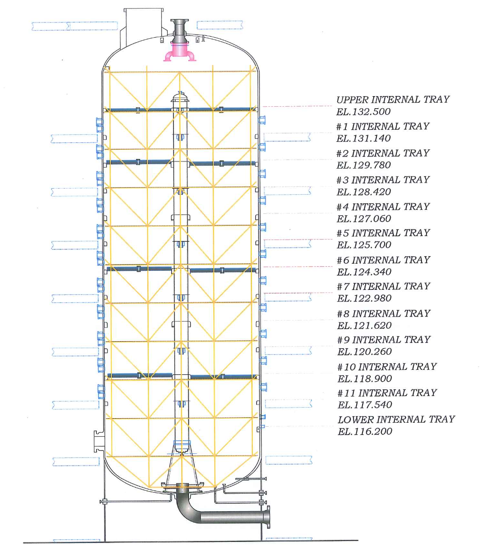
8.8.2.6 On each Intermediate Tray a blanket is installed using a wire rope welded on the center pipe and angle bars welded on the four panels surrounding the center pipe. Refer to Adsorbent Tower data sheet DWG E/13, for further details regarding this item.
8.8.2.7 Tack all weld all potential moving part as: bolts, shim plates.
It is to be pointed out that some steps of the installation of this item have to be done during tray panels inspection and preparation at ground, in particular angle plate welding.
8.8.3 Piping Installation
8.8.3.1 Prerequisite
8.8.3.1.1 Prepare at ground internal pipes and gaskets.
8.8.3.1.2 Check piping portions are properly punch-marked according to punch marking philosophy.
8.8.3.1.3 Check visually the welding inside the piping (restrictions, barbs . . . which to be avoided). Clean or correct if necessary.
8.8.3.1.4 All flexible hoses have been inspected (Temporary protection to be removed, and then reinstalled until final installation).
8.8.3.1.5 The relevant bed walls have been cleaned using vacuum cleaner to remove the sieve dust prior to open the relevant shell nozzles located on the relevant annular chambers.
8.8.3.1.6 All piping shall be blown with air on the top platform in order to remove all foreign materials and dust which might be accumulated inside and outside. If any corrosion or rust is detected during piping unpacking, then it shall be completely removed at ground location, prior to temporary store the internal in its relevant containers.
8.8.3.2 Leak Test
In case of elbows visual inspection is not satisfactory; a piping leak test procedure is issued by AXENS.
8.8.3.2.1 The leak test of the piping will be done outside the adsorbers.
8.8.3.2.2 The leak test duration will be 10 minutes for each piping and no leaks are allowed.
8.8.3.2.3 The pressure test will be 0.5 bar g of instrument air, for both injection and withdrawal piping,
8.8.3.2.4 AXENS will be mandatorily witnessing the test.
8.8.3.2.5 The whole piping including the flexible hoses is completely dried out using IA, prior its final installation after the leak test is completed.
8.8.3.2.6 Any damaged flexible hose is rejected and replaced by a brand new one, to be tested as well.
8.8.3.3 Installation
8.8.3.3.1 Remove blinds from the nozzles of the annular collector and plastic plugs on the tray panel.
8.8.3.3.2 AXENS advisor check annular chamber and panel flange status.
8.8.3.3.3 Connect flange of the piping to the annular chamber. Introduce gasket (in accordance with process specification). and tighten the annular chamber flanges. The other flange of the piping is kept free and is set to the tray’s flange with a protective sheet.
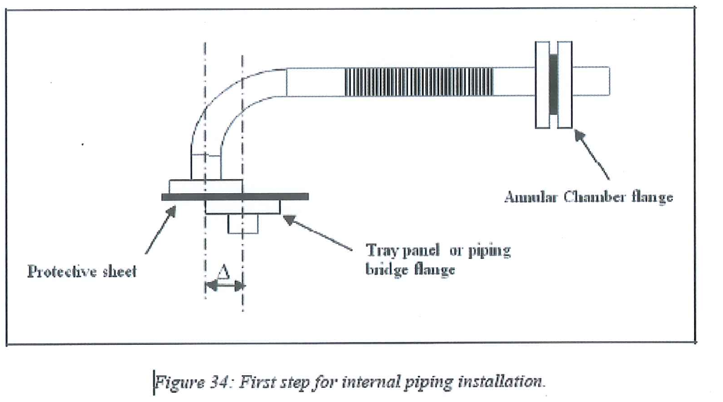
8.8.3.3.4 Operation under AXENS supervision: Position of the horizontal flange is adjusted to fit with the corresponding flange on the tray panel.
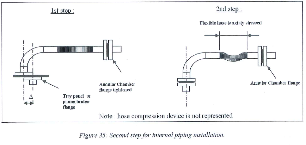
8.8.3.3.5 Check the gaskets (in accordance with process specification).
8.8.3.3.6 Install the gasket and bolt the flange to the collector nozzle.
8.8.3.3.7 Wait for piping supplier or AXENS inspection, (This could be done quadrant by quadrant to avoid losing time waiting for inspection and the green light to go ahead).
8.8.3.3.8 Repeat operation to the next tray panel nozzle.
8.8.3.4 Final Bolting
8.8.3.4.1 Before final bolting, the annular chamber nozzles and inside of the chambers are once again cleaned using special device and vacuum cleaner. This is done bed by bed.
8.8.3.4.2 Special attention to be paid to avoid any gasket damaging during this phase.
8.8.3.5 Final inspection of the piping and stress in flexible hoses is done at the same time as the final inspection of the tray, and just prior to start loading. This final inspection is made by AXENS, whatever inspection the client will want to perform.
8.8.3.6 All necessary measurements are taken by AXENS during this final inspection.
8.8.4 Beams installation (all levels except beams of upper tray) The following guidelines are available for all levels except for beams corresponding to Upper tray.
8.8.4.1 Install the beams as per beams installation procedure.
8.8.4.2 Punch mark each beam once the complete set is installed.
Note: Careful not to damage the internal piping especially the flexible hoses, during beams handling and installation.
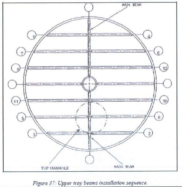
8.8.5 Upper tray beams installation
8.8.5.1 Prepare at ground the beams of the tray.
8.8.5.2 the beams beginning by the 4 beams located on the diameter
8.8.5.3 Check for the relative elevation between beams and annular ring and use shim plates if necessary to achieve satisfactory levelling
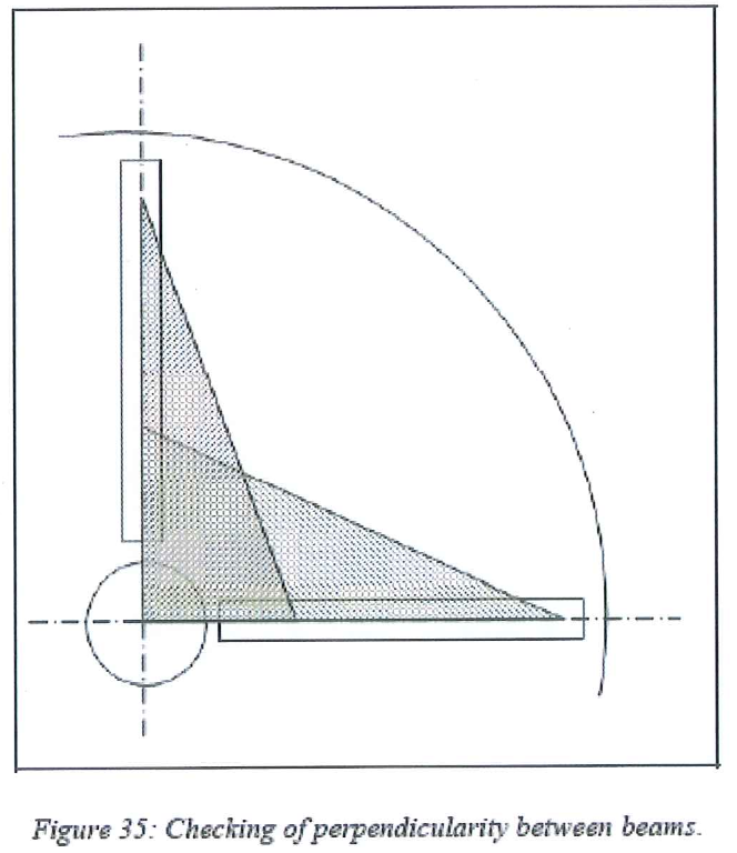
8.8.5.4 Check for the perpendicularity of these 4 beams two by two by measuring the hypotenuse of two virtual triangular shapes in the adsorber for each pair of beams.
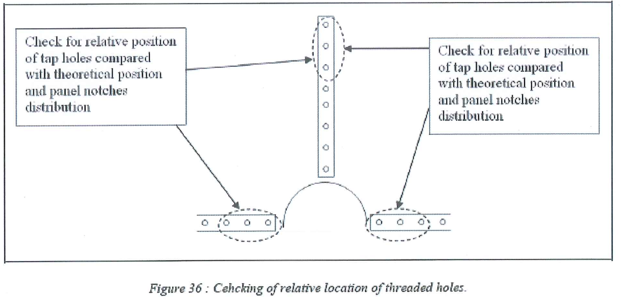
8.8.5.5 For each set of 2 perpendicular beams, check for the relative position of the tap holes on each beam in order to make sure the notches on panel located close to the center pipe will allow bolting.
8.8.5.6 Once the perpendicularity of the 4 beams located on the diameter and adequate relative position of tap holes is achieved, lock the beams in position with shim plates between the beam and the beam support and install bolts.
8.8.5. 7 Check once again the perpendicularity of the 4 main beams and tack weld shim plates and nuts.
8.8.5.8 Then continue installation as per the following beams installation sequence.
8.8.5.9 For each beam:
8.8.5.9.1 Adjust the leveling of the beams using the various thickness shims.
8.8.5.9.2 Adjust the relative position between beams:
8.8.5.9.2.1 check for the perpendicularity with the main beam
8.8.5.9.2.2 Adjust the relative position of tap holes with the gap between main beam
8.8.5.9.2.3 and the parallelism with the secondary beam which is set on the diameter
8.8.5.10 Bolt the beams to the different supports.
8.8.5.11 Check the fastening, the horizontality, the relative position (perpendicularity and parallelism) and the flatness of the beams.
8.8.5.12 Tack weld all potential moving parts: bolts, shim plates.
8.8.5.13 Punch mark the beams once complete set is in position.
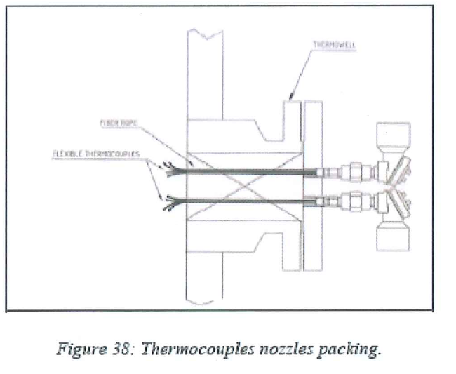
8.8.6 Thermocouples installation
Flexible thermocouples will be installed prior to loading of the relevant bed (for beds 11, 6 and 1 only of each adsorbent tower). This operation is done in accordance with thermocouples manufacturer recommendations. Typical steps for thermocouples installation.
- Tack weld the support clips on the beams.
- Introduce the set of thermocouples through thermowell and tight flange. (check the gasket before installation).
- Unwrap the set of thermocouples and develop them along the beams. Flexible thermocouples have different length depending on the position of the measurement points.
- Be sure that the right thermocouples are on the right position before fixing. Fasten the flexible thermocouple with the support clips.
- Bend the thermocouple at its end, in accordance with the right position described in the process data book. Minimum bending radius of thermocouples: 100mm.
- Pack glass fiber rope inside the nozzle and around the thermocouples to avoid dead volume, as necessary.
(AXENS to supply in due time detailed procedure for flexible thermocouples installation)
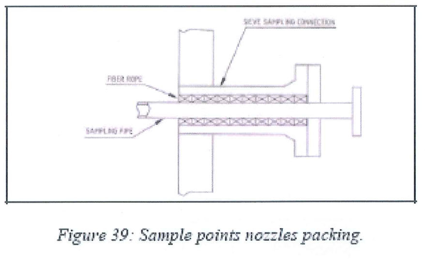
8.8.7 Sample point connection
8.8.7.1 Sample points to be installed prior to loading the relevant bed (for beds 1 of each adsorber)
8.8.7.2 Installation requires fiber rope to be packed inside the nozzle and around the sample devices to avoid dead volume, if necessary.
8.8.8 Tray Inspection
8.8.8.1 Clear out the tray
8.8.8.2 Check thermocouples are in place.
8.8.8.3 Check all gaskets are in place and check the good tightening of flanges.
8.8.8.4 Check the integrity of the flexible hoses for which protective shell had been removed for installation.
8.8.8.5 Dismount the bottom part of the center pipe ladder.
8.8.8.6 Remove neoprene sheets from the panels.
8.8.8.7 Clean perfectly the panel screen with vacuum cleaner.
8.8.8.8 Inspect carefully the screen. Use feeler gauges when visual inspection is questionable.
8.8.8.9 Refer to appendix B for main AXENS inspection check points regarding lower tray.
8.8.8.10 Final inspection will be performed as per AXENS check-list.
8.8.9 Sieve Loading
8.8.9.1 Load the sieve as per AXENS sieve loading procedure as described for Lower Tray.
8.8.10 Next Intermediate trays
8.8.10.1 Repeat operations described in previous chapter
8.8.10.2 Continue sieve loading of bed 1 until the sieve reaches the top level of next tray beams.
8.8.10.3 Regarding beams and panels arrangement, trays are alternatively odd and even from the bottom to the top intermediate trays.
8.8.10.4 Following the progress of the loading, fresh air intakes are to move up. Upper tray beam arrangement and installation sequence is the same as for bottom tray.
8.9 Upper tray installation procedure
8.9.1 Prerequisite
8.9.1.1 Bed below is loaded and beams have been installed with special care regarding perpendicularity (refer to chapter 8-e).
8.9.1.2 The adequate dump-nozzle is open and air circulation is in service
8.9.1.3 Panels of the tray have been prepared at ground as per procedure.
8.9.1.4 Atmosphere inside the Adsorber is breathable (no apparent dust).
8.9.1.5 Support rings and top faces of beams are clean (of any sieve particles or any other material).
8.9.1.6 The Catapac apparatus and the support platform have been removed.
8.9.1.7 Plugs from beams threaded holes have been removed and threaded holes in the beams do not present any damage and are clean.
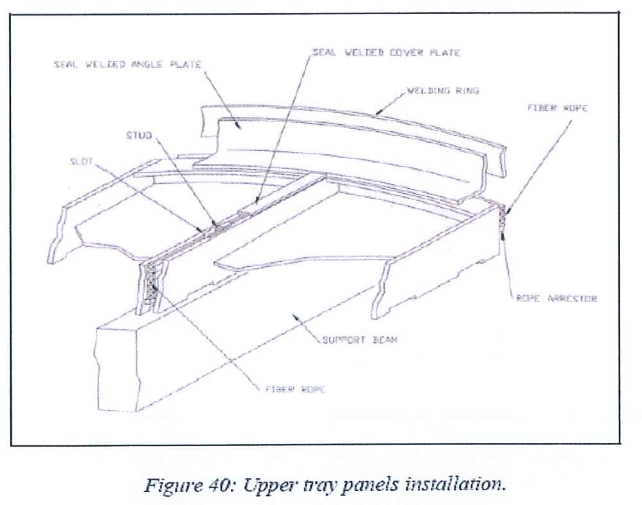
8.9.2 Upper tray panels installation
8.9.2.1 Install the panels following the procedure described for the lower tray.
8.9.2.2 Tighten the stud bolts with washers.
8.9.2.3 Remove the 15 mm thickness spacers progressively.
8.9.3 Tightness and bolting procedure for upper tray
8.9.3.1 Pack the glass fiber rope in each space. Pay attention around each stud. Use smaller diameter rope when necessary.
8.9.3.2 Check the horizontality and the flatness of the tray.
8.9.3.3 Tack weld the seal angle plates on the welding ring of the shell.
8.9.3.4 Install and GTAW weld the panel to panel seal plates.
8.9.3.5 GTAW weld the seal angle plates on the welding rings of the shell and center pipe and the tack welded plates of the round edge of the panel.
8.9.3.6 As for lower tray, an alternating welding scheme must be followed to prevent warping of the panels by localized hot points.
8.9.4 Upper piping manifold installation
This operation must be performed after completion of tightness and bolting of tray.
- Introduce top piping manifold into the top head of the vessel.
- Install the gasket and tighten the inlet distributor box.
- Install preassembled piping between the inlet distributor box and the corresponding panel nozzle.
- Use the piping GTAW welding procedure. Dye test all weldings
- Connect the flushing line to the center-pipe.
- Blind the equilibrium device nozzle.
8.9.5 Center pipe, upper tray and piping manifold leak test
8.9.5.1 General
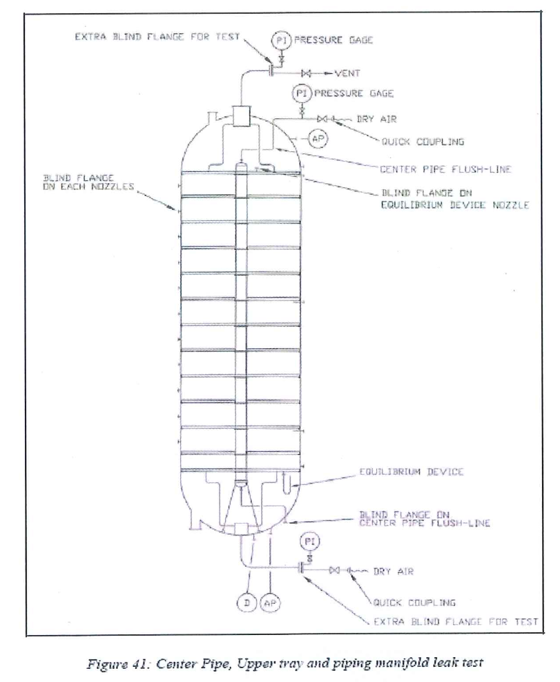
8.9.5.2 Center-pipe pressurization
- Install a temporary flange with an accurate pressure gauge and a valve connected to dry air on the top nozzle of the center-pipe. Blind the bottom nozzle.
- Pressurize the center-pipe under dry air at 0.5 bar g. Leak test is satisfactory when the pressure decrease is lower than 0.05 bar/h over a period of 4 consecutive hours. Keep pressure on the center-pipe during the next steps.
8.9.5.3 Leak Test
- Check the equilibrium device nozzle is blind.
- Manhole is maintained open.
- Install a temporary blind flange equipped with an accurate pressure gauge on the pump around inlet (the temporary blind flange already used for the lower tray leak test is already in place on the pump around outlet).
- Top head piping manifold is air-tested in the same time.
- Close the vent on the temporary flange of the pump around inlet.
- Pressurize the bottom head and the vessel under dry air at 0.05 bar g.
- Check the integrity of the tray and of the top piping manifold by controlling the pressure local indicator. In case of loss of pressure, use a surface-active agent (soap solution) to detect the leakage.
- If any leakage is detected, paint mark it. Depressurize the vessel and repair the defective welding. Pressurize back the bottom head to check the repair.
- Perform these steps until the leak test is fully satisfactory.
8.9.5.4 Vessel pressurization and mechanical resistance of the upper tray
- During this step no entry inside the vessel is allowed.
- Bottom head under dry air at 0.3 bar g. The whole vessel except the top head will be air tested. The upper tray will be air tested to a differential pressure of 0.3 bar. Test is satisfactory when the pressure decrease is lower than 0.05 bar/hover a period of 4 consecutive hours.
- Depressurize the vessel.
- Verify visually the mechanical integrity of the different pieces of the tray.
8.9.5.5 Top head closure
- Depressurize the vessel.
- Remove the blind flange and install the equilibrium device.
- Plug all nozzles of the top head.
- Connect internal piping to the equilibrium device (flushing and sampling lines).
- Clean carefully the upper tray and the top piping manifold.
- Close the manhole.
- Refer to appendix C for main AXENS inspection check point regarding upper tray.
8.9.5.6 General Leak test of the vessel
- Pressurize the vessel as previously at 0.1 bar g.
- Check the integrity of the vessel by controlling the pressure local indicators. In case of loss of pressure, use a surface-active agent (soap solution) on the different nozzles to detect the leakage.
- If any leakage is detected, paint mark it. Depressurize the vessel and repair the defective connections. Pressurize back the bottom head to check the repair.
8.9.5.7 Waiting position
Blind adsorbent tower and place it under nitrogen blanketing (0.1 bar.g)
8.10 Standby Procedure
8.10.1 Presentation
This procedure is developed to plan what to do to secure sieve and vessel in case of temporary interruption of loading and internals assembly operations. Interruption may occur periodically (shift change or rest day) or in emergency situation ( crane hoist breakdown, air or electrical failure, rainy day … This procedure must be applied once interruption lasts more than 2 hours.
8.10.2 Procedure
8.10.2.1 Materials requested
- Temporary blind and suitable gasket for nozzles and manholes. They must be metal sheet and equipped with a vent (no pressure resistance is required).
- Final blind flange on inlet and outlet pump around lines with suitable gasket.
- Blind Flange and plug on each nozzle with suitable gasket.
- During sieve loading
- Close the supersack to protect the remaining sieve.
- Block the slide valves located downstream the receiving hopper and close the lid to prevent the sieve from moisture.
- Empty the catapac apparatus if possible and stop it 8.10.2.2.4 Dismount and remove all obstacles located inside the manholes (Catapac feeding sleeve, ladder, electrical cables, air lines … )
- Switch off the lights inside the vessel.
- Replace the transparent plastic cover by temporary blind on both manholes.
- Connect dry air (dew point -40°C) hose to the vessel (use a nozzle highly above the bed which loading is in progress).
- Ventilate with dry air at minimum flowrate.
- Make sure all the other nozzles are blind and the top deck shelter is properly closed.
- Remarks
-
- If there is any risk of moistening inside the receiving hopper, empty it entirely. Collect the sieve in 200 ltr drum equipped with plastic bag. Close the bag and the sieve tightly. Record the weight of the sieve collected.
- As far as possible loading must not be stopped. If interruption of work is foreseen, it is advised to schedule it after sieve loading of a bed completion or before beginning sieve loading of a bed.
8.10.3 During internals assembly
- Evacuate personnel from the vessel.
- Switch off the lights inside the vessel if any.
- Dismount and remove all obstacles located inside the manholes (Catapac feeding sleeve, ladder, electrical cables, air lines … ).
- Switch off air compressors if they are still running. Connect the vessel to the dry air (dew point -40°C).
- Ventilate with dry air at minimum flowrate to slightly overpressure the vessel.
- Make sure all the other nozzles are blind and the top deck shelter is properly closed.
8.11 Damages and Nonconformity
8.11.1 Any damages and defects and nonconformity found at site shall be reported immediately.
8.11.2 QC Inspector will be responsible for all required documentation.
9.0 QUALITY CONTROL
9.1 QC Personnel shall be assigned to ensure the quality control requirement of the project.
9.2 QC Personnel will coordinate with inspector, SAPID & Axen Licensor to conduct inspection as required.
9.3 QC Inspector shall be responsible to conduct all required inspection/documentation and to ensure that all applicable requirements, codes, and standards are complied with SAIC/SATIP.
9.4 Contractor has to utilize the applicable SAIC for every activity.
10.0 SAFETY PRECAUTION
10.1 First we need to take work permit approval from company representative to start any work.
10.2 Safe work execution shall be carried out in accordance with method statement. And in compliance with Saudi ARAMCO project specification.
10.3 Continuous monitoring and inspection shall be implemented to detect and correct unsafe practices while performing the work activities.
10.4 Persons involved in this job shall have trainings especially in confined space and working at heights.
10.5 Provide warning sign and sufficient barricade on working area and only assigned personnel will be allowed in the area.
10.6 Isolate any inlet connection to the vessel before any activities to be carried out inside the vessel.
10.7 Before each initial entry, gas testing shall be conducted to confirm safe to work inside the confined space.Gas testing shall be verified every day prior to start activity and maintain the log sheet. Gas test shall be conducted twice a day, morning and after lunch. Additional test should be carried out as per task requirement (personal gas monitor shall be used inside the vessel).
10.8 A standby manways watchman/vessel attendant who is competent and trained emergency rescue procedures shall be assigned to maintain an entry and exit logHe will be responsible and make sure that all those who entered have also exited thconfined space. Bravo shall be use as mode of communication between the entraand hole watch attendant.
10.9 Proper lighting arrangement and safety precaution as per safety procedure must be followed.
10.10 Monitor total hours of work inside the equipment of each works.
10.11 Safety Supervisor/Officer shall monitor the work activities to help and to protect aassigned workers against exposure to safety hazards. He shall ensure that Person Protective Equipment (PPE’s) are supplied and used and comply with applicable standards.
10.12 Housekeeping shall be maintained and working area shall be kept in a clean antidy manner.
10.13 Job Hazard and Risk Assessment (JHRA) of this method statement shall be disseminated and explained to workers for safety awareness.
11.0 Related Articles:
Following article are useful to read more about Installation of Adsorbent Tower Internals & Sieve Loading.
- Job Hazard and Risk Assessment (JHRA)
- LOWER TRAY INSPECTION POINT | TOWER INTERNALS
- INTERMEDIATE TRAY INSPECTION POINTS | TOWER INTERNALS
- UPPER TRAY INSTALLATION NOTES | TOWER INTERNALS
- Vendor recommendation for installation
- Rope Packing Procedure
- Air Tightening test procedure for annular chamber
- Field Preservation Procedure J12-C-0201 A/B
- Weld Repair procedure for piping/beam J12-C-0201 NB
- Trial Assembly Procedure
- Center Pipe Centering Procedure
- Lower Tray Leak Test Procedure
- Annular Chamber and Internal Piping Leak Test Procedure
- Sieve Loading Procedure
- LOI Procedure
- Upper Tray Leak Test Procedure.