1. Purpose – This article is about types of manifold valves, manifold valve manufacturer, manifold valve for pressure gauge, 5 way manifold valve, instrument air distribution manifold, manifold valve assembly, 5 valve manifold, 2 way manifold valve and this engineering article is about minimum requirements for manifold valve assemblies to be used with pressure and differential pressure instrumentation.

2. Instrument Manifold Valves and Minimum Technical Requirements
- This specification applies to all 2-, 3-, and 5-valve manifolds supplied to Air Products.
- Alternate methods of construction or materials may be offered by suppliers if they offer a lower-cost solution. All such alternatives require Company’ specific written approval.
Exception: This specification does not apply to ultrahigh-purity plants.
3. RELATED ARTICLES
Oxygen Clean (Class AA) Inspection and Acceptance Requirements
4. Different Types of Instrument Manifold Valves
What is Two-Valve Manifold? Refers to a block and vent manifold used with pressure transmitters, indicators, switches, and other pressure-sensing instruments (see Figure 1).
Figure 1 – Two-Valve Manifold

What is Three-Valve Manifold? Refers to a block and equalization manifold used with differential pressure transmitters, indicators, switches, and other instruments that have two pressure- sensing connections (see Figure 2).
Figure 2 – Three-Valve Manifold

What is Power Industry Five-Valve Manifold? Refers to a block, equalization, and vent manifold used with differential pressure transmitters, indicators, switches, and other instruments that have two pressure-sensing connections (see Figure 3).
Figure 3 – Power Industry Five-Valve Manifold

What is Gas Metering Five-Valve Manifold? Refers to a special block, equalization, and vent manifold that is used in special gas paymeter applications (see Figure 4).
Figure 4 – Gas Metering Five-Valve Manifold

What is Coplanar Flange? Refers to a proprietary connection system supplied with the Fisher Rosemount 3051 Series pressure and differential pressure transmitters.
What is Direct-Coupled Manifold? Refers to manifolds that are directly connected to the transmitter inlet process connections without tubing or intermediate fittings.
5. Instrument Manifold Valves Design Requirements
5.1 Materials of Construction
-
- Manifold bodies shall be machined from 316 stainless steel bars.
- The use of carbon steel for any components of the manifold assembly is specifically prohibited.
- Internal metallurgy shall be selected to prevent galling of components.
- Valve trims shall be stainless steel unless otherwise defined on the Unit Specification.
- All components and parts shall not corrode in a normal industrial atmosphere.
5.2 Valve Trims
-
- All valve trims shall be needle-type with a nonrotating plug.
- Packing shall be PTFE or GRAFOIL as called for in the Unit Specification.
- Valve actuation shall be by a tee handle.
- Valve bonnet shall be positively pinned to the manifold body to prevent unscrewing by the operator.
- Valve packing and seat leakage shall be bubble tight when new and shall remain bubble tight for a minimum of 200 operations.
5.3 Connections
-
- The process inlet connections shall be 1/2 inch NPT unless otherwise defined on the Unit Specification.
- The vent connections shall always be 1/4 inch NPT female and shall be fitted with stainless steel plugs.
- The instrument connections shall be as called out in the Unit Specification.
- For all direct-coupled manifolds, the supplier shall include stainless steel mounting bolts to connect the manifold to the transmitter and shall include the appropriate sealing gaskets and washers. Sealing gaskets and washers shall be PTFE or Grafoil as called for in the Unit Specification.
5.4 Pressure Rating
Manifold valve assemblies shall have a minimum pressure rating of 270 bar g (3915 psig) at 20°C (68°F).
5.5 Mounting
-
- Mounting brackets, when supplied, shall be suitable for an NPS 2 pipe stand.
- All mounting brackets and mounting hardware shall be vibration- and corrosion-resistant.
5.6 Cleaning
Cleaning requirements will be defined on the Unit Specification.
5.7 Tagging and Labeling
-
- The supplier shall identify manifolds with the Air Products tag numbers by hard stamping the body.
- Manifold inlet, outlet, and the valve arrangement shall be clearly identified on the body by either engraving or by label plate.
- Valve bodies shall be stamped with the pressure and temperature ratings.
5.8 Code Requirements
-
- The manifold supplier shall ensure that all units supplied comply with the code requirements of the destination country.
- When orders are destined for use in the European Union, it is the supplier’s responsibility to comply with all EU directives and standards and CE mark the equipment appropriately.
5.9 Model Numbering for Manifold Valves
-
- The Air Products model numbering system will be used by Air Products when specifying and ordering manifold valves assemblies.
- The model number will be made up from AAAAA-BB-C-D-EE-F using Table 1 as follows:
Table 1
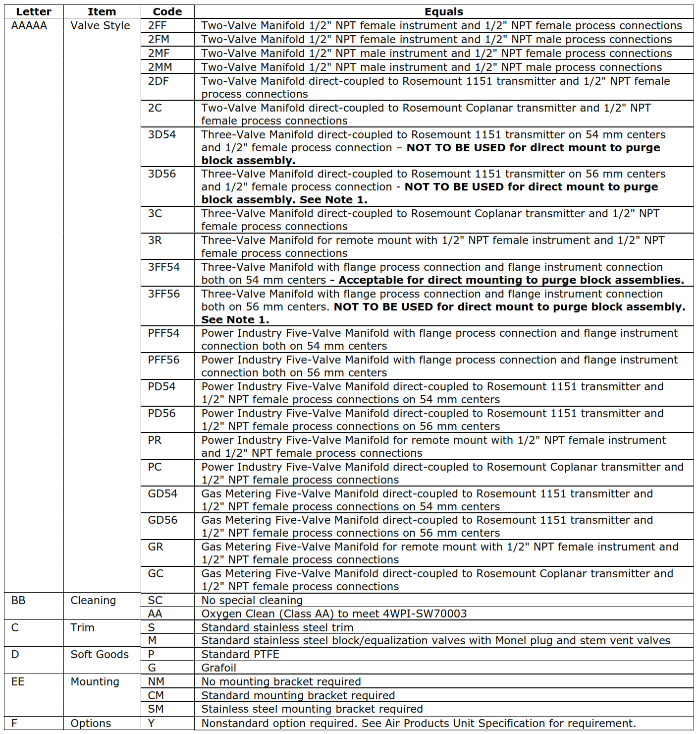
| Letter | Item | Code | Equals |
| AAAAA | Valve Style | 2FF | Two-Valve Manifold 1/2″ NPT female instrument and 1/2″ NPT female process connections |
| 2FM | Two-Valve Manifold 1/2″ NPT female instrument and 1/2″ NPT male process connections | ||
| 2MF | Two-Valve Manifold 1/2″ NPT male instrument and 1/2″ NPT female process connections | ||
| 2MM | Two-Valve Manifold 1/2″ NPT male instrument and 1/2″ NPT male process connections | ||
| 2DF | Two-Valve Manifold direct-coupled to Rosemount 1151 transmitter and 1/2″ NPT female process connections | ||
| 2C | Two-Valve Manifold direct-coupled to Rosemount Coplanar transmitter and 1/2″ NPT
female process connections |
||
| 3D54 | Three-Valve Manifold direct-coupled to Rosemount 1151 transmitter on 54 mm centers and 1/2″ female process connection – NOT TO BE USED for direct mount to purge block assembly. | ||
| 3D56 | Three-Valve Manifold direct-coupled to Rosemount 1151 transmitter on 56 mm centers and 1/2″ female process connection – NOT TO BE USED for direct mount to purge block assembly. See Note 1. | ||
| 3C | Three-Valve Manifold direct-coupled to Rosemount Coplanar transmitter and 1/2″ NPT
female process connections |
||
| 3R | Three-Valve Manifold for remote mount with 1/2″ NPT female instrument and 1/2″ NPT
female process connections |
||
| 3FF54 | Three-Valve Manifold with flange process connection and flange instrument connection both on 54 mm centers – Acceptable for direct mounting to purge block assemblies. | ||
| 3FF56 | Three-Valve Manifold with flange process connection and flange instrument connection
both on 56 mm centers. NOT TO BE USED for direct mount to purge block assembly. See Note 1. |
||
| PFF54 | Power Industry Five-Valve Manifold with flange process connection and flange instrument connection both on 54 mm centers | ||
| PFF56 | Power Industry Five-Valve Manifold with flange process connection and flange instrument connection both on 56 mm centers | ||
| PD54 | Power Industry Five-Valve Manifold direct-coupled to Rosemount 1151 transmitter and
1/2″ NPT female process connections on 54 mm centers |
||
| PD56 | Power Industry Five-Valve Manifold direct-coupled to Rosemount 1151 transmitter and
1/2″ NPT female process connections on 56 mm centers |
||
| PR | Power Industry Five-Valve Manifold for remote mount with 1/2″ NPT female instrument and 1/2″ NPT female process connections | ||
| PC | Power Industry Five-Valve Manifold direct-coupled to Rosemount Coplanar transmitter and
1/2″ NPT female process connections |
||
| GD54 | Gas Metering Five-Valve Manifold direct-coupled to Rosemount 1151 transmitter and
1/2″ NPT female process connections on 54 mm centers |
||
| GD56 | Gas Metering Five-Valve Manifold direct-coupled to Rosemount 1151 transmitter and
1/2″ NPT female process connections on 56 mm centers |
||
| GR | Gas Metering Five-Valve Manifold for remote mount with 1/2″ NPT female instrument and
1/2″ NPT female process connections |
||
| GC | Gas Metering Five-Valve Manifold direct-coupled to Rosemount Coplanar transmitter and
1/2″ NPT female process connections |
||
| BB | Cleaning | SC | No special cleaning |
| AA | Oxygen Clean (Class AA) to meet 4WPI-SW70003 | ||
| C | Trim | S | Standard stainless steel trim |
| M | Standard stainless steel block/equalization valves with Monel plug and stem vent valves | ||
| D | Soft Goods | P | Standard PTFE |
| G | Grafoil | ||
| EE | Mounting | NM | No mounting bracket required |
| CM | Standard mounting bracket required | ||
| SM | Stainless steel mounting bracket required | ||
| F | Options | Y | Nonstandard option required. See Air Products Unit Specification for requirement. |
1.) Rosemount’s 1151dp ranges 6 and 7 are not recommended for use with purge block assemblies due to the 56 mm C-C dimension. Recommendation when higher ranges are required is the Rosemount 3051CD. Center-to-Center for the 3051CD traditional flange is 54 mm.
- Examples using the Table 1 codes to specify and order a manifold valve assembly are as follows:
- Model Number PD54-AA-S-P-CM is a Power Industry Five-Valve Manifold with 1/2 inch NPT female process connections, direct couples on 54 mm centers, Oxygen Clean (Class AA) to meet 4WPI-SW70003, stainless steel trim, standard PTFE soft goods, standard carbon steel mounting bracket, and no nonstandard special requirements.
- Model number 3R-SC-S-G-SM is a Three-Valve Manifold for remote mount with 1/2″ NPT female instrument and 1/2″ NPT female process connections, no special cleaning, standard stainless steel trim, Grafoil soft goods, stainless steel mounting bracket, and no nonstandard special requirements.
Note: Code letters and numbers within the model number shall be separated as shown by a “-“.