1. Purpose – This technical specification defines design and fabrication requirements for all cold box/can temperature-element wiring installations. More Explanation About Selection of Temperature Elements, Methods of Conduit Installation, Electrical Terminal Box, Choosing Cable/wire for Coldbox Temperature Elements, Testing of Temperature Elements and Functional Check for Rtds and Thermocouples.

2. Temperature Element Wiring Installation Procedure of Cold Box/Can
This article is about all temperature elements installed inside cold boxes/cans.
3. RELATED ARTICLES
4ACB-684002 Temperature Element Terminal Boxes for Cold Boxes/Cans
301310A Thermocouple Wire
320004A RTD Extension Cable
4. TEMPERATURE ELEMENTS
4.1 The type of temperature element will be specified by Company Process Controls.
4.1.1 Immersion-Type Temperature Elements
Figures 1 and 2 indicate the method required for installing immersion-type temperature elements. The material for the temperature element well (Figure 2) and the adapters (Figure 3) must be compatible with the pipe material specification.
4.1.2 Skin-Type Temperature Elements
-
- Figure 4 indicates the method and material required for installing skin-type temperature elements.
- Skin-type temperature elements are purchased complete with wires silver brazed to a metal gasket and need only to be attached to a vessel or pipe with a 1/4 inch-20 UNC bolt.
5. Conduit Installation for Temperature Element Wiring Installation
5.1 Inside Cold Box/Can
5.1.1 Seamless Electrical Metallic Tubing (EMT)
-
- Seamless electrical metallic tubing (EMT) of electro-galvanized steel with rigid conduit fittings (galvanized or aluminum) and EMT-to-thread compression-type adapters shall be used for the main runs. Set-screw type adapters are prohibited. Conduit shall be sized and routed by the fabricator, shall generally follow structural members, and shall not be routed behind bolted, removable panels. Do not support EMT conduit from cold vessel supports or piping.
- Conduit Size and Bend Radius
Number of Cables
|
Nominal Conduit Size mm (in) |
Minimum Bend Radius mm (in) |
Wire Specification 301310A (25% Full) |
Wire Specification 320004A (25% Full) |
| 16 (1/2) | 102 (4) | 2 | 2 |
| 21 (3/4) | 127 (5) | 4 | 4 |
| 27 (1) | 152 (6) | 6 | 6 |
| 41 (1 1/2) | 254 (10) | 18 | 18 |
| 53 (2) | 305 (12) | 30 | 30 |
| 63 (2 1/2) | 381 (15) | 44 | 44 |
| 78 (3) | 457 (18) | 68 | 68 |
-
- Maximum number of bends as established by this specification shall be three per length of EMT conduit.
- EMT conduit supports shall be located every 1800 mm (6 ft) for 16 mm (1/2 in) conduit and 3600 mm (12 ft) for all other sizes, using only the cold box frame or angles welded to the cold box frame. EMT conduit shall be supported with EMT steel straps and steel channels 40 x 20 mm (1 1/2 x 3/4 in) x 14GA (without holes).
5.1.2 Flexible Conduit
-
- Flexible galvanized steel or aluminum conduit [16 mm (1/2 in) trade size] shall be run to within 300 mm (12 in) of the temperature point for skin-type temperature elements, and to the temperature element head for the immersion type (see Figures 2, 3, and 4).
- Allow sufficient slack in the flexible conduit to allow for thermal movement of piping by measuring distance required from conduit fitting to temperature element head and adding an additional 250 mm (10 in) of flexible conduit.
5.2 Outside Cold Box/Can
5.2.1 Rigid Conduit
-
- Rigid, galvanized-steel conduit shall be routed from the cold box/can outside face to the terminal box.
- A conduit seal fitting must be installed between the box/can face and the terminal box to prevent purge gas from migrating into the terminal box.
- After testing has been completed in compliance with Section 8, the fabricator shall install filler fiber dam and sealing compound in the conduit seal fitting.
6. TERMINAL BOX
- The terminal box shall be mounted on the outside of the cold box with preferably a 50 mm (2 in) air space [minimum 25 mm (1 in)] behind it to prevent any frost accumulation in or on the junction box (see Figure 4). On large, shop-assembled cold boxes, the terminal box may be recessed into the face of the cold box to reduce the overall shipping dimensions. In this case, the 50 mm (2 in) air space must be maintained. Use 50 x 50 x 6 mm (2 x 2 x 1/4 in) carbon steel angle and 1/4 inch UNC x 1 inch LG round-head machine screws with lock washers and hex nuts to mount the terminal box.
- The terminal box shall be constructed according to 4ACB-684002.
- The terminal box sizing criteria shall include 10% spare terminals.
- After the terminal box is mounted and the conduit has been routed to the box, the cold box/can fabricator shall drill a 13 mm (1/2 in) diameter hole in the terminal box and install the breather drain supplied with the terminal box.
7. CABLE/WIRE
- Skin-type, temperature-element cable shall be one continuous length to the terminal strip in the terminal box and shall not be spliced. Immersion-type, temperature-element cable shall be one continuous length from the terminal block in the element head to the terminal box and shall not be spliced.
- Sufficient wire shall be coiled in the element head to allow complete withdrawal of the element without disconnecting the wires. Extreme care shall be taken when coiling the wires inside the element head to avoid damage to the wire insulation.
- All wires shall be clearly identified at both the element and the terminal box. Permanent tags are required.
Immersion-Type Temperature Elements
Thermocouple-Type Temperature Elements
-
- For the thermocouple cable specification, see 301310A. Air Products will provide to the fabricator the required quantity of cable.
- All thermocouple cable is 2 conductor with overall shield and drain wire. The drain wire shall be connected to the ground screw in the thermocouple head.
- All thermocouple elements are the duplex type and must have two conductor cables connected to the terminal box.
- The copper wire shall be connected to the copper (positive) terminal and the constantan wire shall be connected to the constantan (negative) terminal at the thermocouple element. Copper is positive (+) with blue color code. Constantan is negative (-) with red color code.
- Crimp-type or other mechanical connectors shall not be used to terminate thermocouple wire. Thermocouple wire shall be terminated directly under the screw head of the proper terminal.
RTD-Type Temperature Elements
-
- For RTD-cable specification, see 320004A. Company will provide the fabricator with the quantity of cable required.
- All RTDs are the duplex type and must have two cables connected to the terminal box.
- All RTD cable is 3 conductor with overall shield and drain wire. The shield and drain wire shall be cut back and insulated using heat-shrink tubing T&B shrink-kon or equal. The cable shield shall not be grounded in the RTD-element head. The cable shield shall be connected in the terminal box.
- The white wire shall be connected to the white terminal in the RTD element and its respective black and red wire connected to the red terminals in the RTD element. Care must be taken so that the red and black wires are not crossed between the A and B sides of the RTD element.
- All wires shall be terminated on the RTD element head at the proper terminal using insulated, locking, fork-crimp-type lugs, Thomas & Betts catalog #RA18-6FL or equal. Terminal lugs shall be crimped using the lug manufacturer’s approved, ratchet-type crimping tool.
- All wires shall be terminated at the terminal blocks at the proper terminal without the use of crimp-type lugs or ferrules.
8. TESTING
8.1 Skin Type
Skin-type temperature elements are calibrated by Company before installation and, therefore, they do not require testing after installation.
8.2 Immersion Type
8.2.1 Cable Check
After installation of the cable and wiring to the junction box mounted on the cold box/can face, but before connection of the thermal elements, the cable and conduit installation shall be tested as follows:
-
- Using a “Megger” or similar device, check each cable and record the resistance of each of the following:
Core to core
Core to cable screen
Core to earth
Cable screen to cold box/can steelwork (earth)
-
- Minimum resistance must be 500 k ohms at least 100V.
After installation and connection of the elements, the following checks shall be made, using preferably a Digital Multimeter (DMM) on a resistance range. If such an instrument is not available, an analogue-type meter set on a resistance range may be used. Under no circumstances is a high voltage device (such as a Megger) to be used.
-
- For each cable/element, check and record the resistance of each of the following: Core to core
Core to cable screen
Core to earth
Cable screen to cold box/can steelwork (earth)
-
- Ambient temperature shall also be recorded.
Note: For thermocouples, the core to core readings will show a small resistance (of the order of 0–25 ohms) through the element, while RTDs will show either slightly greater than 100 ohm, or a small resistance (of the order of 100–110 ohms).
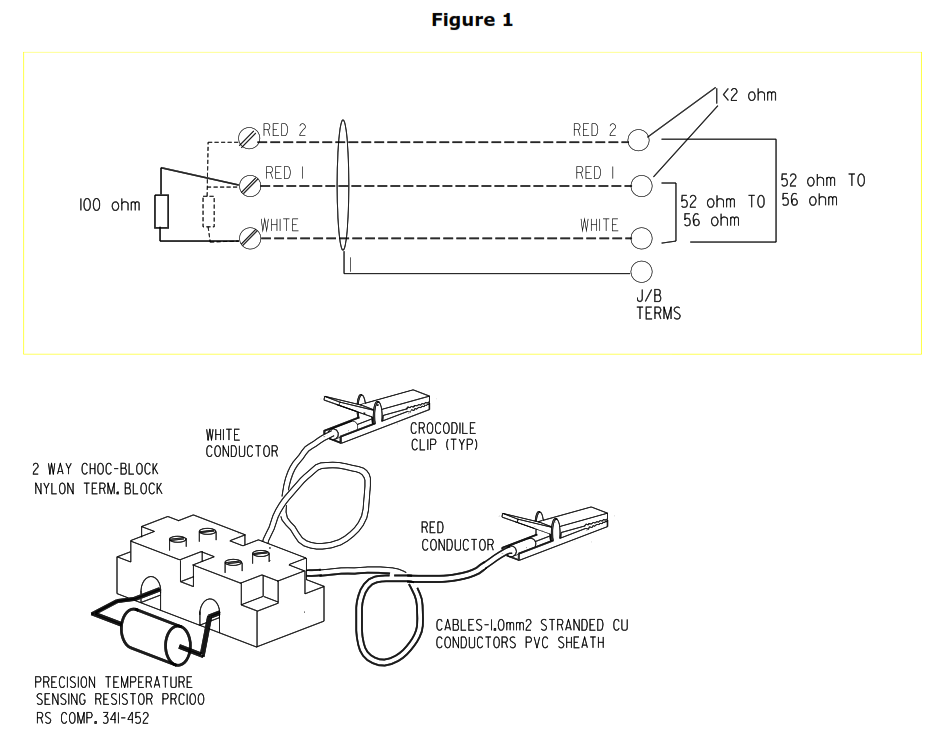
8.2.2 Functional Check for RTDs
-
- For RTDs, after element connection and wiring is completed, and before the element head being fitted, a calibration continuity check is to be performed as follows.
- A 100 ohm resistor test assembly is to be temporarily connected to the element head between the terminal connections “white” and “red”(1) as shown below in Figure 1.
- The resultant readings are to be read off at the junction box terminals with a DMM or a bridge instrument set on a resistance range.
- The readings are to be read between “white” and “red”(1), and “white” and “red”(2); these shall be within the range of 52 ohm and 56 ohm respectively. A final reading between “red”(1) and “red”(2) should result in a reading of <2 ohm.
- The results shall be recorded on the test record. If the results are outside those indicated above, a fault exists and should be rectified.
Figure 1
8.2.3 Functional Checks for Thermocouples
- For thermocouples, elements shall be tested for continuity and accuracy by removing them from their well and immersing them in liquid nitrogen. Electromotive force (EMF) measurement, read at terminal box end of wires, shall be -5.532mV ±0.036mV at -195°C (- 320°F) with a 0°C (32°F) reference. If a direct temperature readout device is used, the reading shall be -195°C ±2.2°C (-320°F ±4°F) with a 0°C (32°F) reference. Wires shall not be disconnected at the thermocouple element head during or after this test.
- Extreme care shall be taken when recoiling the wires inside the temperature element head to avoid damage to the wire insulation.
Figure 2 – Temperature Element Well Installation Detail for 65 (2 1/2 in) and Larger Pipe
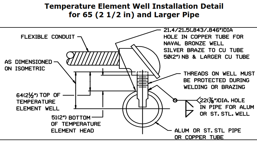
Figure 3 – Temperature Element Well Installation Detail for 50 (2 in) and 40 (1 1/2 in) Pipe
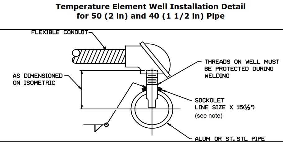
Note: For line sizes less than 40 (1 1/2 in), increase line to 50 (2 in) or 40 (1 1/2 in)
Figure 4 – Skin-Type Temperature Element Installation Detail

À Servit, Connector, Burndy #KS 90
Á Cable/Wire (As Provided by Air Products)
 Connector Box 16 (1/2 in) Flex Straight T&B #3112
à Conduit Flexible Galvanized Steel 16 (1/2 in)
Ä Wire, Number 8 AWG, 7 Stranded Copper, Type TW Black
Å Wire, Number 6 AWG, Stranded Aluminum, Bare ASTM B231
Æ Thermocouple Adapter, Air Products Drawing #54268B
Figure 5 – Typical Installation of Junction Box
(Actual Configuration of Fitting May Be Altered To Suit Horizontal or Vertical Entry to Junction Box)
