This article establishes a uniform method for selecting and specifying the most common types of level measuring instruments used on projects. Main keywords for this article are Level Transmitters Selection Types of Level Transmitters. Level Transmitters Applications. Bubbler Type Level Transmitter Calculation Differential Pressure.
Level Transmitters References
ANSI (American National Standards Institute)
B16.11 latest edition, Forged Steel Fittings, Socket Welding and Threaded Connections
B31.3 latest edition, Petroleum Refinery Piping Code For Pressure Piping
API (American Petroleum Institute)
ASME (American Society of Mechanical Engineers)
Boiler and Pressure Vessels Code, Section I, latest edition, including addenda.
CSA (Canadian Standards Association)
FM (Factory Mutual)
NFPA (National Fire Protection Association)
UL (Underwriters Laboratories)
Level Transmitters Selection and Types of Level Transmitters
This article, in addition to providing detailed sections and specification information for level sensing instruments, also provides guidelines for the application of the following types of level sensing instruments:
a. Bubbler
b. Capacitance Type
c. Differential Pressure
d. External Displacer
e. Float and Tape Type
f. Load Cell System
g. Nuclear Method
h. Ultrasonic
The measurement of liquid level in a vessel or tank can be accomplished by many different methods and a wide variety of instruments. Satisfactory performance can be achieved by several of the instruments and therefore the selection of the instrument best suited must be based on the specific application.
Level Transmitters Applications
This article also addresses types of level indicators and transmitters such as analog and digital types of tank gaging. It outlines the codes and special installation requirements that apply to level instruments in
certain services. It also outlines required interfaces with other disciplines.
Bubbler
A bubbler system using a top mounted transmitter can be used in open vessels. This system consists of an air supply, a pressure regulator, a constant flow meter, a pressure transmitter, and a bubble tube
extending down into the vessel. Air is bubbled through the tube at a constant flow rate. The pressure required to maintain flow is determined by the vertical height of the liquid above the tube opening times
specific gravity.
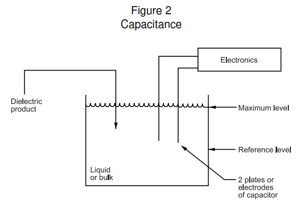
Capacitance Type
These devices require one or more probes that extend the length of the level span to be measured. If a liquid is a good conductor of electricity, such as water, the probe is a metal rod covered with an insulator. As liquid rises around the insulated electrode, the liquid forms the second electrode of a capacitor and the capacitance increases accordingly. If the liquid is a dielectric, the probe is a metal rod, surrounded by a metal tube with a predetermined space between the two. As the liquid level rises between the electrodes, the capacitance increases proportionately.
Differential Pressure
These transmitters, used for liquid level, measure hydrostatic head pressure. This pressure is equal to the liquid height above the tap multiplied by the specific gravity of the liquid. It is independent of volume or vessel shape.
Open Vessels
- In open vessels, a pressure transmitter mounted near the bottom of the tank will measure the pressure corresponding to the height of the fluid above it.
- The connection is made to the high pressure side of transmitter and the low pressure side is vented to the atmosphere.
- If the zero point of the desired level range is above the transmitter, zero suppression of the range must be made.
Closed Vessels
- In closed vessels, the pressure above the liquid will affect the pressure measured at the bottom. The pressure at the bottom of the vessel is equal to the height of the liquid multiplied by the specific gravity of the liquid plus the vessel pressure.
- To measure true level, the vessel pressure must be subtracted from the measurement. This is accomplished by making a pressure tap at the top of the vessel and connecting this tap to the low pressure
side of a differential pressure transmitter. The resulting differential pressure is proportional to liquid height multiplied by specific gravity.
Dry Leg
If the gas above the liquid is noncondensable, the piping for the low side of the transmitter will remain empty. Calculations for determining the range will be the same as shown for open vessel, bottom mounted transmitters.
Wet Leg
- If the gas above the liquid is condensable, the piping for the low pressure side of the transmitter will slowly fill up with liquid. To eliminate this potential error, the pipe is purposely filled with a convenient reference fluid. Most commonly used reference fluids are glycerin or glycol.
- The reference fluid will exert a head pressure on the low side of the transmitter and zero elevation of the range must be made.
External Displacer
These are usually used for level measurement with a minimum range of 14 inches and liquid-liquid interface service, and have external body material fabricated of carbon steel with stainless steel displacer
and torque tube. Use air fins or heat insulators at operating temperatures above 400 degrees F and below 0 degrees F for displacers with pneumatic pilots. Wherever displacers with electronic transmitters are used, provide air fins or heat insulators above 250 degrees F and below 0 degrees F. The connections are normally 1-1/2 inches flanged with bottom side and top side connections. Rotatable heads should be
specified.
Float and Tape Type
This type is normally used for tank level application and consists of a buoyant float, spherical or flat, that rests directly on top of the liquid. The float is connected by a tape or cable to an indicator or gagehead on the outside of the tank. The float may be guided by guide wires or by a perforated stilling well to assure free operation of the float. Electronic transmitter or switch contact block may be coupled to the gagehead to accomplish a variety of requirements. This device’s measure of direct level is applicable to most liquid specific gravity and is economical for open tanks however the moving parts are exposed to the process fluid, to breakage of tape and are limited in pressure rating.
Load Cell System
In this method, the contents of a storage vessel or tank are determined by weighing the tank plus the fluid and subtracting the weight of the vessel or tank. The tank or vessel is usually supported on load cells. In load cells, strain gages are bonded to a calibrated compression column. Changes in the mass of the vessel contents produce resistance changes in the strain gages and a bridge circuit detects the changes.
A summing circuit totalizes the signals to indicate gross weight knowing the weight of the tank. The net weight of the tank contents is calculated.
Nuclear Method
Radiation type gaging system measures the amount of gamma rays that are absorbed by the liquid in the tank. In this system, the source of gamma radiation, such as cobalt 60, is placed in a vertical column on
the outside of the vessel. The measuring cell or detection is located diametrically opposite the source on the other side. The intensity of gamma rays received by the detector is inversely proportional to the height of liquid in the tank. This is due to the fact that absorption of gamma rays is a function of the mass of material between the radiation source and the detector. The radiation absorbed by the vessel wall is a constant that is canceled in the circuitry.
Ultrasonic
Some types of gaging system use the principle of speed of sound and time taken to traverse a distance. A sound generator is placed at the top of the tank and transmits pulses towards the liquid surface. The
reflected sound wave is received by a pick-up transducer, and the control unit computes the distance based on time span for the waves to reflect and be received.
Level Transmitters Selection
The selection of the measuring instrument is based on the type of measurement required and material availability. It is important that the correct material is selected for components that come in contact with the process fluid.
Explanatory Notes, Calculations, And Examples
Bubbler Type Level Transmitter Calculation
An example of bubbler can be found in, Figure I.
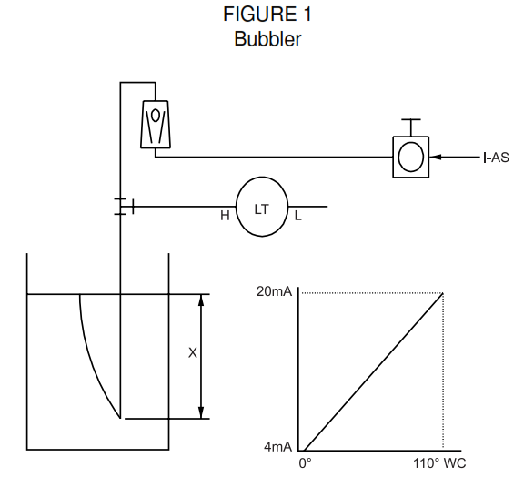
Let:
X = Vertical distance between minimum and maximum levels equals 100 inches.
SG = Specific gravity equals 1.1
h = Maximum head pressure to be measured in inches of water.
Range = Zero to h
Then,
h = (X) x (SG) = 100 x 1.1 = 110 inches, WC (water column)
Range = 0 to 110 inches WC
Capacitance Type Level Transmitter Calculation
Figure II shows an example of a capacitance type. In this case, two electrodes which are conducting metal rods or plates, are spaced apart in the fluid. The height of the fluid level varies, thereby linearly increasing or decreasing the capacitance between the two electrodes.
Differential Pressure Level Transmitter Calculation
This is the most common type used for measurement of level both in pressurized and open vessels. An example of a bottom mounted transmitter in an open vessel is shown in Attachment 01, Figure 3.
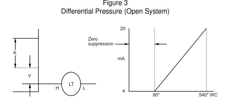
Where:
K = Vertical distance between minimum and maximum measurable levels equals 500 inches.
Y = Vertical distance between the transmitter datum line and the minimum measurable level equals 100 inches.
SG = Specific gravity of the fluid equals 0.9.
h = Maximum head pressure to be measured in inches WC.
e = Head pressure produced by Y in inches WC.
Range = e to (e + h)
h = K x SG = 450 inches WC.
e = Y x SG = 90 inches WC.
Range = 90 to 450 inches WC.
A closed vessel application is shown in Figure IV. If the gas above the liquid level is noncondensable, the piping for the low pressure side of the transmitter will stay dry or empty. Calculations for determining the range will be the same as those shown for open vessel, bottom mounted transmitters. This is a typical dry leg application.
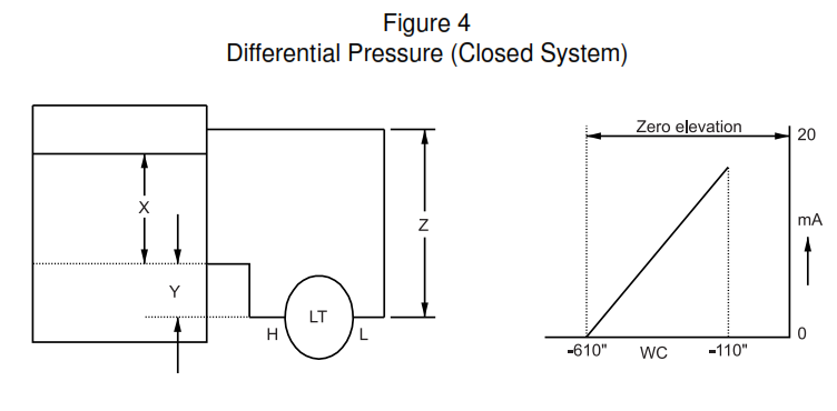
The example below provides a calculation method for determining the range of the transmitter when the gas or vapor above the liquid is condensable. This is a typical wet leg application.
Let:
x = 500 inches.
y = 50 inches.
z = 60 inches.
SG1 = Specific gravity of fluid in the vessel equals 1.0.
SG2 = Specific gravity of fluid in the wet leg equals 1.1.
h = Maximum head pressure to be measured.
e = Head pressure produced by Y in inches WC.
s = Head pressure produced by Z in inches WC.
Range = (e – s) to (h + e – s).
h = X x SG1 = 500 x 1.0 = 500 inches WC.
e = Y x SG1 = 50 x 1.0 = 50 inches WC.
s\ = Z x SG2 = 600 x 1.1 = 660 inches WC.
Range = -610 to -110 inches WC.
The wet leg is usually filled with a reference fluid that exerts a known head pressure on the low pressure side of the transmitter. To overcome this, zero elevation of the range must be made. Refer to Figure IV,
which shows zero elevation of the range to provide 4 mA output at -610 inches WC pressure differential.
Installation considerations
During the selection of the measuring device, appropriate consideration should be given to the following:
a. The economics of the measuring device’s installation.
b. The flexibility of re-ranging the device if the level data should change.
c. The availability of utilities and auxiliaries at the location of the device.
d. The suitability of the device in the located electrical area classification.
e. Ambient conditions may dictate thermal insulation, heat tracing for freeze protection, and purged enclosures to prevent corrosion.
Level Transmitter Code Requirements
- In all cases, the instrument device manufacturers will furnish certifications provided by test laboratories such as UL (Underwriters Laboratories), CSA (Canadian Standards Association), FM (Factory
Mutual) and others. The certifications will verify tests conducted and the conformity to various codes and standards such as ANSI (American National Standards Institute) classes for flanged connections,
pressure and temperature ratings of pressure containments, suitability of performance in NFPA, and API stipulated electrical areas such as Class I, Division 1 and 2, groups A, B, C, and D. - In addition to the above information on pressurized system applications, piping to the device shall be in accordance with the latest edition of ANSI Code for Pressure Piping, ANSI B31.3, Petroleum Refinery Piping and ANSI B16.11, Forged Steel Fittings, Socket Welding and Threaded Connections.
- Installation piping that connects level measuring devices to power boilers or unfired steam generating equipment will be in accordance with the latest edition of ASME (American Society of Mechanical Engineers) Boiler and Pressure Vessels Code, Section I, including addenda.
- The limits of piping governed by codes other than ANSI B31.3 shall be indicated on the P&ID (Piping and Instrumentation Diagram).
Interface Between Disciplines
Process Data Transfer
a. The Process Engineer on the project provides the process data relating to the physical properties of fluids, and the operating and design conditions.
b. In addition, on level applications, the maximum and minimum level datum, interface points and interface levels are defined. If a PFD (Process Flow Diagram) with stream identification does not exist
on the project, the Process Engineer should fill in the appropriate process information on the instrument datasheets.
Mechanical (Vessel) Data Transfer
The Vessel Engineer will review the nozzle requirements for level instruments with a sketch of the proposed vessel prior to making a vessel RFQ (Request For Quotation). The Vessel Engineer also determines the material of the vessel and will provide design data for the vessel that should be used when writing the instrument datasheets.
Piping Data Transfer
The Piping Engineer determines the piping line classes based on operating requirements. Material selection for in-line piping valves is also provided by the Piping Engineer. Piping issues both a material
specification and a line class listing on the project. It is necessary to follow piping standards on the piping associated with the installation of level measuring devices.
Vendor Information Transfer
Vendor information regarding gage glasses, displacer type level instruments, and level switches external displacer type are required by the Piping Engineer to develop bridle and other installation details and to carry out stress analysis. During the drawing approval cycle, mechanical vessel drawings are routed through the Instrument Engineer, who will verify the size and elevation of connections for level devices and sign off the drawing with comments, if any.
Level Transmitter Zero Suppression
- It is essential to determine precisely the extent of zero elevation or zero suppression required for calibrating the device. This is based on the location of the device with respect to the desired level range.
- Going back to the example in Attachment 01, Figure I, the zero point of the desired level range is above the transmitter tap location, therefore zero suppression of the range must be made to produce a 4
mA transmitter output when the differential pressure equals 90 inches, water column.
Level Transmitter Zero Elevation
In the example of wet leg shown in Figure IV, the reference fluid will exert a head pressure on the low pressure side of the transmitter. This head pressure will vary from -110 inches, water column to -610
inches, water column. The liquid level in the vessel will be at minimum when the head pressure is -610 inches, water column. Therefore, zero elevation of 610 inches, water column must be made to produce a 4 mA output at -610 inches, water column head pressure. Normally, elevation or suppression should not exceed D/P cell maximum range.
Surge Volumes
- In general, it is the responsibility of the Process Engineer to establish the surge volume. It is the responsibility of the Control Systems Engineer to provide a level control that will cover the holdup times
required, based on maximum inflow rates provided by the Process Engineer. It is also up to the Control Systems Engineer to verify that the surge volume is adequate to permit satisfactory control. - In order for a level controller to work satisfactorily, it is necessary that the response time at which the controller and valve operate be faster than the rate that the level can change within the vessel. This rate of level change can be stated as the surge time in seconds for the liquid level to move from the top of the range to the bottom of the range with instant shutoff of the inlet. Wherever control valves are controlling surge level, the minimum surge time should be as shown on the following table.

- The above surge times will, in general, give good control if the control air line to the control valve is less than 50 feet, and the pressure drop across the control valve is less than 75 psi. Where excessive pressure drop or a longer control air line exist, additional surge time will be required.
Note: Main keywords for this article are Level Transmitters Selection Types of Level Transmitters. Level Transmitters Applications. Bubbler Type Level Transmitter Calculation Differential Pressure.
Thanks