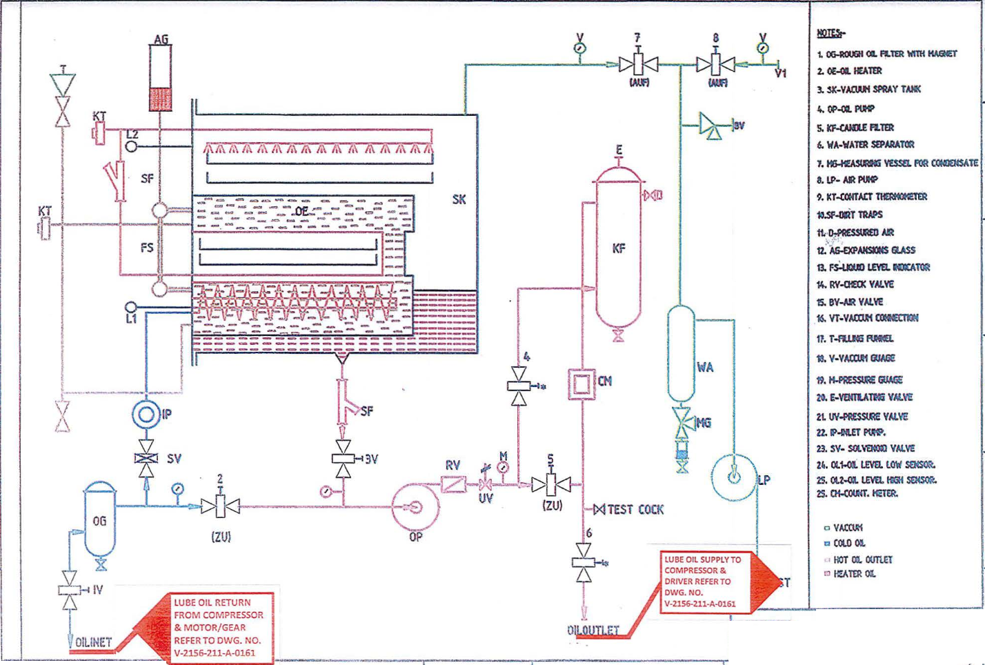
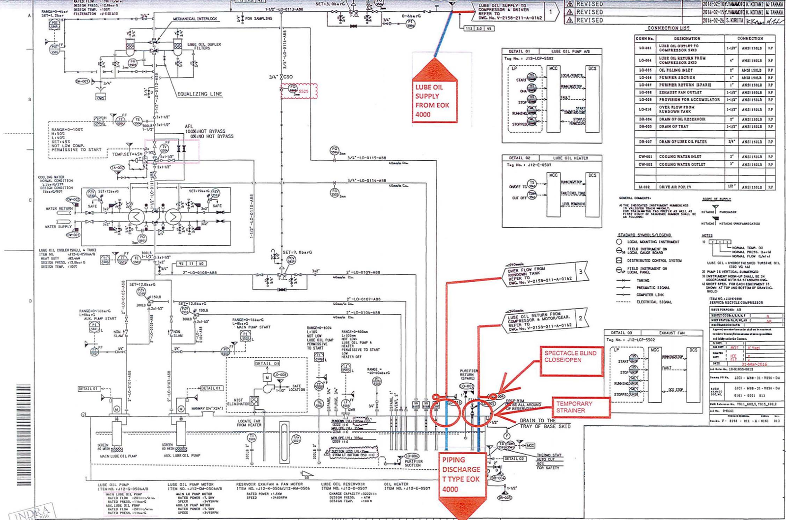
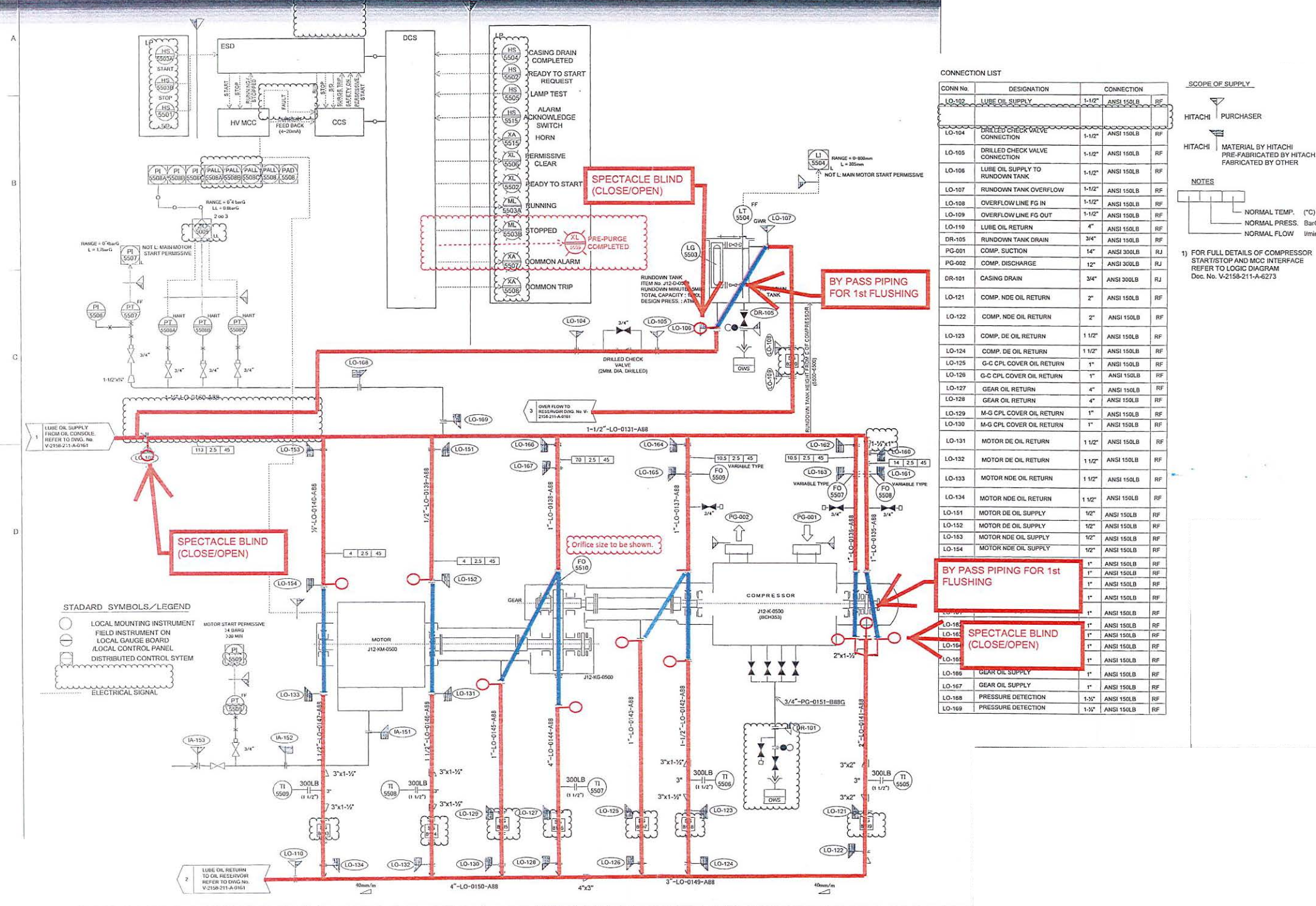
This article is about Lube Oil Flushing Procedure and method statement of Centrifugal Compressor and pipelines for plants and refinery projects. Here more explains about lube oil flushing calculations.
1.0 PURPOSE.
2.0 SCOPE.
3.0 APP LI CABLE DOCUMENTS.
4.0 RESPONSIBILITY.
5.0 MANPOWER.
6.0 TOOLS AND EQUIPMENT.
7.0 METHODS/PROCEDURE.
8.0 QUALITY CONTROL.
9.0 SAFETY PRECAUTION.
10.0 ATTACHMENTS.
1.0 PURPOSE
The is Method Statement shall provide minimum guidelines to carry out the Lube Oil Flushing of Centrifugal Compressors and Pipelines for plants and refinery projects in accordance with contract scope of work and project specification.
2.0 SCOPE
This method statement covers the procedure of lube oil flushing of centrifugal compressors for plants and refinery projects and pipe lines .
3.0 APPLICABLE DOCUMENTS
3.1 Project Specifications and Standards
3.1.1 SAEP-302 Instruction for obtaining a waiver of a mandatory Saudi Aramco Engineering Requirement.
3.1.2 SAEP-1 028 Chemical Cleaning and Flushing of Lu be/Seal Oil and Fluid Power Systems.
3.1.3 SAES-G-116 Cleanliness Standard of Lube/Seal Oil and Fluid Power Systems.
3.1.4 SAIC-G-2016 Pre-Cleaning Inspection of the Lube and/or Seal Oil System.
3.1.5 SAIC-G-2017 Mechanical and Chemical Cleaning of Lube and/or Seal Oil System.
3.1.6 SAIC-G-2018 Fin al Cleanliness In spection after Cleaning and Flushing of Lube and/or Seal Oil System.
3. 1.7 SAIC-G-2019 Final Reinstatement after Mechanical and Chemical Cleaning.
3.1.8 SATIP-G-115-01 Lubrication , Shaft Sealing & Oil Systems (Rotating Equipment).
3.1.9 API 686 Recommended Practices for Machineries and Installation Design.
3.1.10 Vendor’s Marked-Up P&l Diagram.
3.1.11 Rel ated Vendor’s Installation and Operational Manuals.
3.1.12 Construction Safety Manual.
3.1.13 Schedule “Q” Quality Requirement.
4.0 RESPONSIBILITY
Construction Manager
He is responsible for implementing HSE and shall stud y, analyze and schedule all construction activi ties with his department to include manpower and equipment line up as well as other possible resources required for the successful implementation of the construction work activities. Study all aspects of work procedure as per Technical Scope of Work.
Mechanical Superintendent
He shall assist Construction Manager in the overall construction activities. Receives and carries out directives and strategies of Construction Manager in various phases of duties assigned by this immediate Supervisor.
Mechanical Foreman
He shall be responsible for the direct work supervision at site and ensure that the work is performed in accordance with JV Technical Scope of Work and specification.
QC Inspector
He shall be responsible to verify the work and ensure that the work is being performed in accordance to project specification standards.
Safety Supervisor/Officer
He shall monitor and ensure that the work is done in accordance with JV Safety Standard Procedure and inaccordance with Saudi ARAMCO Safety Standard Procedure.
5.0 MANPOWER
5.1 The Mechanical Superintendent shall control the overall activity of lube oil flushing works and he shall be directly reporting to the Construction Manager. The basic manpower under him shall consist but not limited to the following:
5.1.1 Mechanical Supervisor.
5.1.2 Mechanical Foreman.
5.1.3 Pipe Fitters/Mechanical Fitters.
5.1.4 Electricians.
5.1 .5 Riggers.
5.1.6 Crane Operators.
5.1.7 Helpers.
5.1.8 Scaffolders.
5.2 Safety Engineers/Officers.
5.3 QC Inspectors.
6.0 TOOLS AND EQUIPMENT
6.1 Tools and equipment needed should be in good condition and must be checked by the Mechanical Supervisor I Safety Officer prior to use in the construction area. These includes but not limited to:
6.1.1 Hand Tools (Wrenches).
6.1.2 Power Tools.
6.1.3 Temporary Strainers I Filter Elements.
6.1.4 Wire Mesh I Filter Net.
6.1 .5 Oil Transfer Drum Pump.
6.1.6 Temporary By-pass Piping I Rubber Hose (1 MPa).
6.1.7 High Temp Gasket.
6.1.8 Clean Rags.
6.1.9 Hand Hammer.
6.1.1 0 Wooden Hammer.
6.1.11 Brush, Sponge.
6.1.12 Sample Can (18 Ltr. Can).
6.1.13 Polyethylene Sheet.
6.1.14 Stick Type Thermometer.
6.1.15 Flow Measurement Device.
6.1.16 Bottle of Sampling (Transparent).
6.1.17 Hand Valves.
6.1 .18 Flow Orifice.
6.1.19 Heating Device and Blanket using on Return Pipe.
6.1.20 Oil for Flushing and Operation al Oil.
6.1.2 1 Power Supply Generator.
6.1.22 Temporary Pumps/Tanks/Heater Control Protection (if necessary).
7.0 LUBE OIL FLUSHING PROCEDURE OF CENTRIFUGAL COMPRESSORS AND PIPE LINES
7.1 General Requirements prior to Lube Oil Flushing
7.1.1 Prior for installation of lube oil piping lines (field fabricated/shop fabricated) air blow shall be done on every parts of lube oil piping lines.
7. 1.2 All accessible welds on pipes and fittings shall be inspected for the presence of weld slag. If slag is found, it shall be removed.
7. 1.3 After completion/acceptance of lube oil piping lines, shall turn-over to chemical cleaning group (by JV) so that chemical cleaning group can conduct necessary chemical cleaning works prior for pressure testing of lube oil piping .
7 .1.4 Immediately after chemical cleaning complete, piping test group shall conduct pressure testing with own fluid test media prior to turn-over to lube oil flushing group. Refer to lube oil packages for pressure testing, test package shall be approved first by JV and ARAMCO prior to conduct testing works.
7.1.5 After completion and acceptance of pressure testing for lube oil lines , lube oil flushing shall commence by lube oil flushing group.
7.2 Preparatory Works for Lube Oil Flushing
7. 2.1 Confirm the turnover/WTS of the lube oil system. The system should be chemically cleaned by prior to lube oi l flush ing.
7.2. 2 Secure work permit from JV concerned personnel prior to start of wo rk activity.
7.2.3 Prepare all materials needed for the job. Installation of scaffolds shall be complete and rigid, enough to withstand loads app lied .
7.2.4 Install and position lightings on best location as per site condition.
7.2.5 Remove all instrument item and control valves such as PC V, PZV, etc.
7.2.6 Inspect the lube oil tank for cleanliness prior to starting flushing operation. Ensure to, by manual clea ning using rag and/or by air blow, clean all lube oil tanks/run down/reservoirs prior to pressure test and lube oil flushing.
7.2.7 Inspect permanent oil pump’s suction strainers for cleanliness as well.
7.2.8 Before to start flushing activities , the site shall be cleaned and paved .
7. 3 Preparatory Inspection
7.3. 1 Al l systems piping , manways, removable headers, filters, coolers, temporary bypass piping etc. shall be inspected for cleanliness prior to installation and bolting.
7.3.2 All surfaces in contact with oil shall have a uniform clean metallic color. The surfaces , when viewed without magnification, shall be free of visible rust. mi ll scale, welding slag , corrosion, oxides, paint or other foreign material.
7.3 .3 All internal surfaces of component parts of field fabricated lube oil system shall be cleaned as described in SAEP-1028, prior to flushing with oil.
7.3.4 If the internal surfaces of any compo nent parts of shop fabricated lube oil piping do not meet the requirements of paragraph 7.3.2, the affected system shall be cleaned in accordance with SAEP-1 028 before flu shing with oil.
7.3.5 Field fabricated tie-in piping shall be isolated and cleaned independently of shop fabricated lube oil piping which complied with Paragraph 7.3.2 of this document.
7.4 Oil Flushing Procedure
Generally cleaning and flushing shall be as per applicable procedures of Vendor’s procedure, SAEP-1028 and REIE686.
7.4.1 1st Flushing Phase
7.4.1.1 Refer to marked-up P&ID for location of temporary materials such as bypass piping , strainers, wire mesh and etc. Bypass location installed as agreed between Vendor, and Company.
7.4.1.2 Drain the existing oil if any from the system . shall collect the old oil with empty containers (drum) and se nd them to a designated disposal facility by an approved service provider.
7.4.1.3 Remove all permanent filter elements. Temporary bypass pi ping and strainer and wire mesh shall be in stalled around all compressor bearings, lube oil tanks, run down tanks and shaft driven lube oil pump (if applicable) .
7.4.1.4 The system should be fill ed with lubricating oil, of the same type and grade as will be used in operation. The volume and level of oil shall be checked and confirmed.
7.4.1.5 If applicable and feasible , permanent pumps shall be used for lube oil flushing. Operation of parallel pumps at the same time may aid in dislodging solid contaminants. The temperature of the oil should be alternated between 40°C (100°F) and 70°C (160°F) every 4 hours. Using reservoir heaters may assist in this process.
7.4.1.6 If use of permanent pump is not applicable or not allowed, temporary pump shall be connected to the permanent lube oil tank and operated for flushing.
7.4. 1.7 During the flushing, the piping should be tapped with a non-marring hammer at all flanges and welds to assist in loosening any weld spatter or pipe scale.
7.4.1.8 Care mu st be exercised in this procedure so as not to exceed the design temperature limitations of the oil coolers.
7.4.1.9 Oil flows must be appropriately monitored and manipulated to achieve complete and effective flushing of all piping and equipment.
7.4.1.10 Replace or clean the temporary strainers if there are signs of plugging of oil flow.
7 .4.1.11 Circulate at 12-hour intervals and check for system cleanliness. The procedure for circulation and checking for cleanliness shall be repeated until Vendor’s representative is satisfied with conditions of the system. Cleanliness of the oil may be checked at convenient discharge locations with a telltale (such as white gauze cloth) as indicated on the lube oil flushing diagram.
7.4.2 2nd Flushing Phase
7.4.2.1 After cleanliness check of 1st flushing , remove all temporary bypass piping and reinstall the permanent oil supply and return piping with temporary 1 00-mesh screens backed with minimum 20-mesh screens. Those screens shall be installed ju st upstream of the bearing housing flange connections.
7.4.2.2 Make sure to supply nitrogen gas to all bearing housings through separation gas supply inlet lines before oil pump start.
7.4.2.3 Resume flushing the system until a 12-hour flush through a clean set of screens yields no magnetic particles, no particles gritty to the touch, and a negligible dirt count on each screen .
7.4.2.4 If the screen indicate the system is not clean after one or two such cycles, re-cleaning of the piping downstream of the strainers should be considered .
7. 4.2.5 Under no circumstances should the machine be rotated without the specific approval of the Vendor’s representative.
7.4.2.6 A sample should be taken at the completion of the oil flushing procedure from the reservoir bottom and checked for water content and dirt contamination.
7.4.2.7 After completion of flushing , Vendor’s representative shall judge the cleanliness of piping in accordance with the acceptance criteria. After the 2nd flushing is completed, the
inspection shall be carri ed out and witness by JV QC and ARAMCO.
7.5 Final Assembly and Acceptance for Service
7.5 .1 Remove all temporary piping, screens and strainer and install all permanent piping including control valves as designated to operate.
7.5.2 All pressure reducing valves to maintain the design oi l pressures sh all be adjusted and set as per specification.
7.5.3 All flow orifices and instrument item previously re moved shall be installed and connected as they are designated to operate.
7.5.4 Install new filter elements.
7.5.5 If permanent nitrogen line is not in service, continue supply of temporary nitrogen to separation gas line of all bearing housings.
7.5.6 New permanent gaskets shall be always used for piping reinstatement.
7.5.7 Pressure Relief Valves for lube oil pumps shall be calibrated for proper operation and setting.
7.5. 8 Remove the used oil for oil flushing completely and fill th e new oil into permanent oil tank. shall collect the used oil with empty containers and send them to a designated disposal facility by an approved service provider.
7.5.9 Operate permanent oil pumps for initial running test. JV Pre-commissioning team shall attend and witness this running test.
7.5.1 0 Check oil pumps and drivers for excessive vibration or temperature.
7.5.11 After confirmation of normal operation condition, circulate two hours and collect a composite
two liter sample from different drains. Send the sample to a laboratory approved by ARAMCO for chemical and physical analysis. Final lube oil acceptance test certificate shall be issued by ARAMCO approved third party.
Checkout this article also: CENTRIFUGAL COMPRESSOR INSTALLATION PROCEDURE | METHOD STATEMENT
INTERNAL CLEANING FOR PIPING PROCEDURE | METHOD STATEMENT
8.1 QC to inspect system to be flu shed prior to filling of lube oil in the system. QC to verify if system is ready for flushing , refer to SAIC-G-20 16 for details.
8.2 QC to check and verify system after flushing as per SAIC-G-2018 and as per the following acceptance criteria:
8.2 .1 No visible accumulation of dirt/nitrogen material is found on the screens after 12 hours of circulation.
8.2 .2 Moisture can not be detected using the Lube Oil Condition Monitoring Program Laboratories hot pl ate crackle test method.
8.2 .3 All surfaces in contact with oil shall have a uniform clean metallic color. The surfaces, when viewed without magnification, shall be free of visible rust, mill scale, welding slag, corrosion, oxides, paint or other foreign material.
8.2.4 The cleanliness of the system is acceptable to the Saudi Aramco proponent organizations operational personnel.
8.2.5 The system oil will be considered acceptable for service when its particle count in accordance with ISO 3938 and ISO 17/14 (equivalent to NAS Class 8).
9.0 SAFETY PRECAUTIONS
9. 1 Construction Manager / Mechanical Supervisor / Foreman shall be responsible for the implementation of this procedure and the required orientation necessary for the work force.
9.2 Safety Supervisor I Officer shall monitor compliance of the entire working crew regarding safety procedures until the work is fully completed.
9.3 Th e necessary manpower inclusive of supervisory staff, tools, equipment, materials and other resources required must be made available and ready to use.
9.4 Provide warning sign and sufficient barricade on working areas to avoid unauthorized entry. Only assigned personnel shall be allowed in the area.
9.5 All workers shall wear mandatory PPE and additional PPE if required .
9.6 Sufficient lighting shall be provided if working in the night.
9.7 Only trained personnel are allowed to work in this activity.
9.8 Good housekeeping must be maintained for the duration of work.
9.9 Never leave oily substances on the operation deck of the equipment to avoid slipping . Take due care when working on the oil console deck.
9. 1 0 Job Safety Analysis of this procedure shall be disseminated and explained to all involve personnel for safety awareness.
9. 11 Required Work Permit shall be prepared and approved appropriately prior to the activity . The approved Work Permit shall be always available at site near the working place.


