1.0 PURPOSE
2.0 SCOPE
3.0 APPLICABLE DOCUMENTS
4.0 RESPONSIBILITY
5.0 MANPOWER
6.0 TOOLS & EQUIPMENT
7.0 METHODS/PROCEDURES
8.0 QUALITY CONTROL
9.0 SAFETY PRECAUTION
10.0 ATTACHMENT
1.0 PURPOSE
1.1 This method statement shall provide minimum guidelines to carry out the Medium Voltage (5kV-35kV Power Cable), Cable Splicing / Termination and Testing works for commercial buildings, plants and refinery projects, in accordance with Saudi Aramco Standards, Project Drawings and Project Specifications.
2.0 SCOPE
2.1 This method statement will cover the minimum requirements for preparation, proper handling safety and conducting DC Hi-Pot Testing and Temination of medium voltage cables for commercial buildings, plants and refinery projects, in accordance with the scope of work, approved for construction drawings, project specification and applicable Saudi Aramco Standards/Procedures.
3.0 APPLICABLE DOCUMENTS
3.1 Project Specification and Standards
3.2 Saudi Aramco Specification and Standards
3.2.1 SAEP-302 Instruction for Obtaining a Waiver of a Mandatory Saudi Aramco Engineering Requirements
3.2.2 SAES-P-104 Wiring Methods and Materials
3.2.3 Schedule Q Saudi Aramco Project Quality Requirements
3.2.4 Schedule G Material, Tools, and Equipments
3.2.5 Schedule D Safety, Health and Environmental Requirements
3.3 Industry Codes
3.3.1 NEC National Electrical Code
3.3.2 CEI IEC 60502-1 Power Cable with Extruded Insulation (1kV up to 30kV)
3.3.3 IEC 60840 International Electrotechnical Commission (Power Cables with Extruded Insulation)
3.4 Inspection and Test Plan/ Method Statement
3.4.1 1770-MS-ELEC-007 Low/Medium Voltage Electrical Cable Installation.
3.4.2 1770-MS-ELEC-002 Grounding Installation and Testing (Above ground and Under Ground).
3.4.3 SATIP-P-104-02 Medium Voltage Cable and Conductors (1.001 kV to 35 kV).
3.4.4 SATR-P-3208 Medium Voltage Power Cable (Installed), Continuity and Megger Insulation Resistance Testing.
3.4.5 SATR-P-3210 Medium Voltage Power Cable, High-Potential Withstand Testing.
3.5 Saudi Aramco Pre-Commissioning Form
3.5.1 SA-P-000 Testing Guidelines
3.5.2 SA-P-041 High Voltage Cables (5kV-15kV-35kV)
3.6 Saudi Aramco Safety, Health and Environmental Standard
3.6.1 Construction safety manual
4.0 RESPONSIBILITY
4.1 Construction Manager is responsible for implementation of all HSE requirements; he shall study, analyze and schedule all construction activities with his department to include manpower and equipment line up as well as other possible resources required for the successful implementation of the construction work activities. He shall study all aspects of work procedure as per Saudi Aramco Standards.
4.2 Electrical Superintendent shall study and review all necessary documents for the installation works to include, technical scope of work, specifications, bill of quantities,
plan milestone dates and construction procedure in support to his Electrical Supervisor. He shall coordinate with the other discipline to visualize possible conflicts in the drawings as well as in the schedules, and to provide other options in preventing unnecessary delays and obstruction. He shall be directly reporting to the Construction Manager.
4.3 Electrical Supervisor shall be responsible in the implementation and control of all activities ensuring that all works are performed in accordance with this method of statement, project specification, approved for construction drawings and Saudi Aramco Standard/Procedures. He shall study and review all necessary documents for DC Hi-pot testing.
4.4 The Electrical Foreman shall be directly responsible for the work supervision at site installation following all schedules and specific work activities ensuring that the works are performed in accordance with Saudi Aramco Standards and latest approved IFC drawings.
4.5 Main (Leader) Jointer is responsible for giving orders I instructions to the site execution team to perform all activities at site as per contract specification based on work schedule and ensure to accomplished works as per standards and respect schedule at all times, maintaining quality of works.
4.6 Assistance Jointers / Helpers is to fully support the team whatever required as necessary to speed up and expedite the work as per milestone date of the Project.
4.7 QC Inspector shall be responsible to verify and inspect the work and ensures that the work is performed and properly documented in accordance with Saudi Aramco Standards and Procedures.
4.8 Safety Engineer shall be responsible in monitoring safety aspects and ensuring that the work is done in accordance with Saudi Aramco Construction Safety Manual (CSM). He shall discuss to the workers the characteristics of related materials and status of work area giving reminders as an additional point to injury and incident free environment.
5.0 MANPOWER
5.1 The Electrical Superintendent shall control the overall activities at site and he will be directly reporting to the Construction Manager. The basic manpower under him shall consist but not limited to the following:
5.1.1 Electrical Supervisor
5.1.2 High Voltage Terminator (Certified)
5.1.3 Industrial Electrician
5.1.4 Electrical Technician
5.1.5 Boom truck operator
5.1.6 Helper
5.2 QC Inspector
5.3 Safety Engineer
6.0 TOOLS AND EQUIPMENT
6.1 Tools and equipment needed should be in good condition and must be checked by Supervisor / Safety Engineer prior to use in the construction area. These includes but not limited to:
6.1.1 Electrical Hand Tools.
6.1.2 High Voltage Module.
6.1.3 Ground Leads.
6.1.4 High Voltage Output Cable .
6.1.5 Interconnection Cable.
6.1.6 Kilovoltmeter.
6.1.7 Grounding Termination Shield Connector.
6.1.8 Semi-conductor peeling device.
6.1.9 Insulation remover.
6.1.10 Conical cutting tool with conical knife.
6.1.11 Gas torch.
6.1.12 Crimping tool hydraulic.
6.1 .13 Megger.
6.1.14 De Hipot test set.
6.1 .15 Diameter measuring tape.
6.1.16 Nylon Ropes.
6.2 All tools utilized in a classified area should be intrinsically safe and suitable for hazardous areas.
7.0 METHOD STATEMENT / MEDIUM VOLTAGE POWER CABLE SPLICING, TERMINATION & TESTING PROCEDURE
7.1 GENERAL PREPARATORY WORKS (SPLICING & TERMINATION)
7.1.1 All permanent materials, consumables, equipment to be installed and its accessories, construction area and resources shall be prepared and checked prior to installation works.
7.1.2 Work Transfer Sheet shall be duly signed and processed by other subcontractors or discipline for the preceding works to avoid confusion and discrepancies in the work responsibilities.
7.1.3 Special tools shall bear a valid calibration certificates traceable to a national standard indicating calibration validity and periodically (at least six months) checked by a third party laboratory testing facility.
7.1.4 Electrical materials shall conform to all applicable requirements, standard, and specifications prior to release to be used as part of the work. Refer to Schedule “Q” Att. IV Para 7.1.
7.1.5 Review all references such as the latest approved for construction drawings, layout, and Technical Scope of Work.
7.1.6 The Personnel who will be involved in the works so called us the “Cable Splicer/ Terminator shall hold a valid MV Cable Certification Card issued by Saudi Aramco.
7.1.7 Cable Splicer’s / Terminators upon request shall carry a copy of their while working on the Power Cable. As per SAEP-1150 Para. A.18.
7.1.8 Design and Installation of Wiring and Cable Systems shall be in accordance with the NEC as supplemented by SAES-P-104 and/ or as approved Saudi Aramco Standards.
7.1.9 Ensure that Manufacturers documentation for the Medium Voltage Cable splicing / termination kit shall be studied for compatibility with Saudi Aramco Standards and the cable being spliced/ terminated as per NEC 110.38.
7.1.10 Cables shall be permanently identified prior to the Splicing / Termination process; Ref SA Std. SAES-P-104 6.10.
7.1.11 The Vendor Instruction Manual requirements shall be incorporated into the installation procedure. NEC 110.38; Ref SA Std. SAES-P-104 4.1.
7.1.12 All Compression Dies / Connectors shall have a Manufacturer’s Reference compression die number and conductor size normally printed or stamped on the connector as required as SAES-P-104 Para. 6.1.
7.1.13 Medium and High Voltage terminations (operating at 2.4 kV and above) installed outdoors shall have a minimum creepage distance to ground of 40mm per kV line-to-line nominal system voltage as per SAES-P-104 Para.
6.12.2 Medium and High Voltage terminations installed indoors shall have a minimum creepage distance to ground of 25mm per kV line-to-line nominal system voltage; Ref SA Std. SAES-P-104 6.12.3
7.2 CABLE SPLICING AND TERMINATION
7.2.1 Detailed Installation Joints for Screened 3-Core Plastic & Rubber Insulated Cables 7.2 kV to 17.5 kV with wire Armour.
TABLE-1 – Size of Conductor mm2

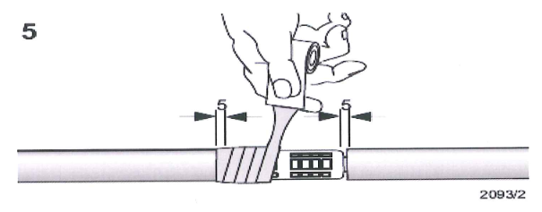
7.2.1.1 Overlap the cables to be jointed by 100 mm. Mark the reference line (the middle of the overlap). Slide the shortest of the three sealing sleeves over the short side of the joint. Fold and tape it down temporarily so that the next sealing sleeve can be slid over it. Tape down the second sealing sleeve over the first one. Position the remaining sealing sealing sleeve over the two sealing sleeves.

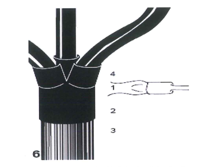
7.2.1.2 Remove the oversheath, armour and bedding according to the dimensions A or B given on Table 1. Do not cut the earth conductor (if any). Slide the screw clips over the cable ends. Lift the armour wires and slide the support rings underneath as shown in drawing A. Build up the bedding under the support ring with a piece of oversheath. Secure the ends of the armour wires with a wire binder. Shape and position the cores are shown in drawing A and cut them at the reference line.

7.2.1.3 Cables with wire shields: Remove the metal tape shield according to
the dimension c given in Table 2.
Cables with extruded core screens – Remove the extruded semi conducting screen according to the dimension d given in Table 2.
Note: Do not nick the Insulation!
Clean and degrease the insulation. Wrap plastic tape round the insulation 10 mm above the end of the core screen. Cover the 10 mm of the insulation and about 5 mm of the core screen with conductive paint. Wait until the paint has dried and then remove the plastic tape.

7.2.1.4 Cables with metal tape shields: Twist the shielding wires together to form an earth conductor.
Cables with tape screens and conducting layers – Remove the semi conducting tape screen according to the dimension d given in Table 2.
Note: Do not nick the Insulation.
Cover the end of the semi-conducting tape screen and the first 10 mm of the conducting layer with plastic tape (adhesive side upwards). Completely remove every trace of the conducting layer. Use a solvent recommended by the cable manufacturer. Remove the plastic tape. Cover the 10 mm of conducting layer and about 5 mm of the semi conducting tape screen with conductive paint.

7.2.1.5 Slide one combined tubing set over each long core end.
1. Stress control tubing (black)
2. Insulating tubing (red)
3. Screened insulating sleeve (black and red)

7.2.1.6 Joint the conductors by crimping, soldering or any other equivalent method. Remove any sharp edges. Clean and degrease the insulation. For maximum dimension of connectors see table 3.

7.2.1. 7 Remove one paper from the void filling compound (yellow) and roll it up. Wrap it around the connector with a 50% overlap stretching it to about half of its original width. Fill up the connector area continuing onto the insulation for not more than 5 mm.
Note: Do not use to much void filling compound.
The final diameter should be only slightly greater than the core or connector diameter, whichever is larger.
7.2.1.8 Smooth out the surface of the insulation with a thin film of silicon grease. Slide the stress control tubing (black) over the completed connector area before taping the other cores.

7.2.1.9 Position the stress control tubing centrally over the connectors. Start shrinking in the center working towards the end. The tubing should be fully shrunk and wrinkle free.
Note: Take care not to accidentally shrink the other tubing at this stage.
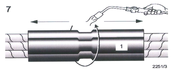
7.2.1.10 Pull the insulating tubing (red) from the inside of the screened tubing (black & red) and position is centrally over the stress control tubing. Start shrinking in the center working towards the ends.
Note: continue immediately with step 9 while the insulating tubing is still hot.
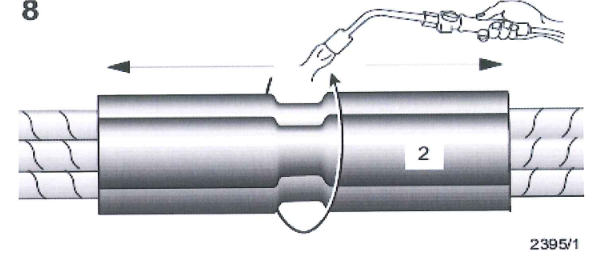
7.2.1.11 Position the screened insulating tubing (black and red) centrally over the previously installed tubing. Start shrinking in the center working towards the ends. The tubing should be fully shrunk and wrinkle free.

7.2.1.12 Cables with wire shields — Relay the cores as far as possible. Wrap all the copper braid round the cores with a 50%overlap so that the whole joint area is covered. Join the earth conductor by crimping or any other equivalent method.
7 .2.1.13 Cables with metal tape shields – wrap two layers of copper braid with a 50% overlap round each joint area, continuing for 20 mm onto the metal tape shield. Attach the copper braid to the metal tape shield on both sides of the connector area by soldering or any other equivalent method (such as Raychem solderless earth connection, see EPP 0184) to maintain shield continuity. Relay the cores as far as possible.

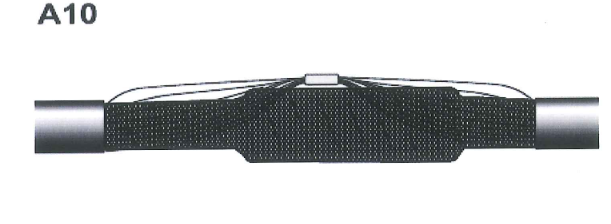
7.2.1.14 Wrap the joint case round the joint and secure with about two layers of cloth tape as shown in the picture. Clamp the ends of the joint case onto the steel wire armour using the screw clips. Cover the sharp edges of the screw clips by fastening a piece of cable oversheath over the screw with the remaining cloth tape.

7.2.1.15 Slide the first long sealing sleeve over the long side of the joint. Position the sleeve so that it overlaps for 150 mm onto the oversheath. Shrink it into one place starting from the joint area and working towards the oversheath.

7.2.1.16 Position the second long sealing sleeve over the center of the joint.
Overlap the previously installed sealing sleeve by 150 mm. Start shrinking in the center working towards the end.

7.2.1.17 Position the short sealing sleeve over the short side of the joint.
Overlap the oversheath by approximately 150 mm. Start shrinking at the joint area working towards the oversheath.

7.2.1.18 Allow the joint to cool before applying mechanical stream.

7.2.2 Detailed Installation for the termination of Screened 3-Core Polymeric Insulated Cables 7.2 kV to 36 kV:
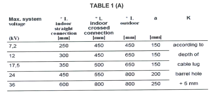
*L = min. length required
The actual length will be determined by the overall geometry of the equipment.
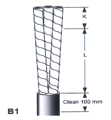
7.2.2.1 Cut the cable to the required length and remove the oversheath.
Leave enough length to set the cores into their final. Clean and degrease the end of the oversheet for about 100 mm.
Note: the minimum termination legnth (L) is given in Table 1.

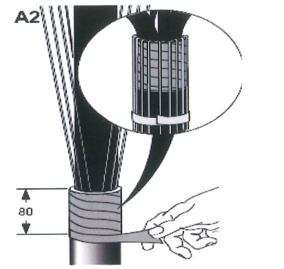
7.2.2.2 Remove the release paper and wrap one layer of sealant tape (red) with a small overlap and slight tension around the end of the oversheath for 80 mm. bend the shielding wires back onto the oversheath. Avoid crossing individual wires. Temporarily fix the shielding wires well below the red sealant tape to the oversheath. For cables with tape armour also connect to the earth lead to the armour. For cables with wire armour follow the instruction as supplied in separate armour earthing kit.
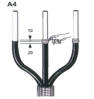
7.2.2.3 Bend and shape the cores into their final position. Cut the cores to the required length. Thoroughly remove the core screen according to dim. a (see Table 1 ). The surface of the insulation should be free from all traces of conductive material. Smooth out any irregularities.
Note: do not nick the insulation!

7.2.2.4 Remove the release paper and wrap the void filling strip (yellow) around the end of the core screen. Cover 20 mm of the core screen and continue onto the insulation for 10 mm. Stretch the strip to half of its original width to achieve a fine, thin edge onto the insulation.
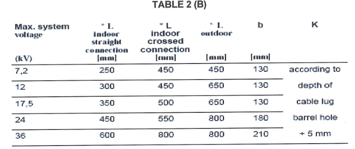
*L = min. length required
The actual length will be determined by the overall geometry of the equipment
7.2.2.5 Cut the cable to the required length and removed the oversheath. Leave enough length to set the cores into the final position. Clean and degrease the end of the oversheath for about 100 mm.
Note: the minimum termination length (L) is given in Table 2.
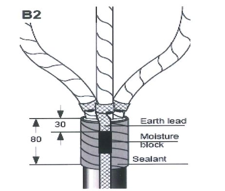
7.2.2.6 Separate the cores. Wrap an earth lead around each core and soldertack it to the metal tape shield (or attach the earth lead by any other equivalent method). Fill the earth lead with solder to form a 30 mm from the oversheath end. Remove the release paper and wrap one layer of sealant tape (red) round the oversheath end of 80 mm underneath the earth lead. For cables with tape armour also connect the earth lead to the armour. For cables with wire armour follow the instruction as supplied in armour earthing kit.
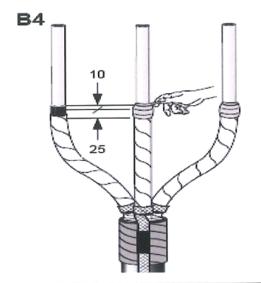
7.2.2.7 Bend and shape the cores into their final position. Cut the cores to the required length. Place a temporary wire binder around the cores at the position shown in the drawing. Tear off the tape shield against the wire binder. Remove the metal tape shield according to dimension b (see Table 2). Thoroughly remove the screen to 20 mm above the metal tape shield. Cut the surface of the insulation should be free from all traces of conductive material. Smooth out any irregularities.
Note: do not nick the insulation.

7.2.2.8 Remove the wire binder from the end of the metal tape shield.
7.2.2.9 Remove the release paper and wrap the void filling strip (yellow) for 5 mm onto the metal tape shield, continuing over the core screen and 10 mm onto the insulation. Stretch the strip to half of its original width to achieve a fine, thin edge onto the insulation.
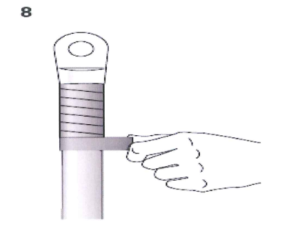
7.2.2.10 Place the stress control tubing (black) over the cores and position them 70 mm above the end of the oversheat cut. Shrink down the tubing starting at the bottom and working upwards.
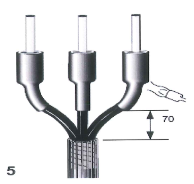
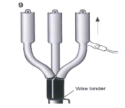
7.2.2.11 Remove the release paper and slide the breakout over the cores. Pull the breakout as far from the crutch as possible. Shrink the breakout into place starting at the center. Works first towards the lower end and then shrink the turrets onto the cores. The numbers in the drawing indicate the shrinking sequence.
7.2.2.12 Cut back the insulation according to dimension K = depth of cable lug barrel hole + 5 mm. Install the cable lugs. Clean and degrease the insulation and the lugs .

7.2.2.13 Remove the release paper and wrap the sealant tape (red) around the barrel of the cable lug with a small overlap and slight tension. Note: Use the remaining sealant tape (red) to fill any remaining gap between the core insulation and the cable lug.
7.2.2.14 Remove the release paper and wrap the sealant tape from the red tubing. Place the tubing. Place the tubing over the cores with the sealant coated and downwards. Push the tubing over the breakout turrets as far as possible and shrink it out down starting at the crutch and working upwards. Tie the shielding wires or the earth lead with a wire binder to the oversheath below the breakout. Gather the shielding wires together to form an earth lead.
7.2.2.15 Cut the tubing back onto the connector barrel if necessary. Post heat the palm of the lug until a bead of mastic appears around the top of the tubing.
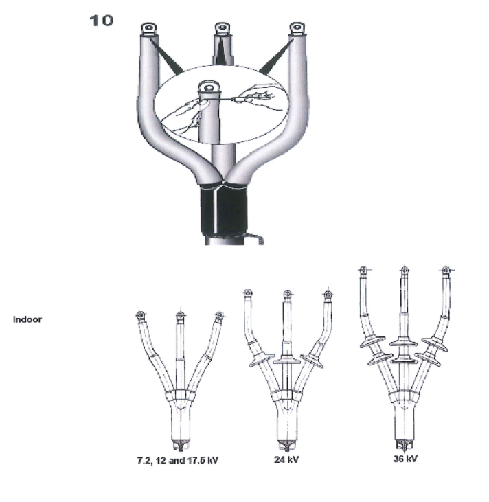
7.2.3 Termination Completed
7.2.3.1 Allow the termination to cool before applying any mechanical strain. For indoor terminations above 17.5 kV to 36kV and outdoor terminations shrink the skirts into place as shown below.

7.3 GENERAL REQUIREMENTS/ OVERVIEW FOR CABLE TESTING
7.3.1 Only qualified employees are allowed to perform high voltage test or work.
7.3.2 Installer Contractor shall appoint qualified employees as their ‘competent persons’. Such persons shall be capable of working safely and shall be knowledgeable on the precautionary techniques, personnel protective equipment, shielding and insulating materials and tools.
7.3.3 High voltage cables shall be DC high-potential tested in accordance with SAES-P-104 Para. 13.
7.3.4 This DC hi-pot testing applies to cable voltage rated 5kV and above. Refer to SAES-P-104 Para. 13.3, Table 3).
7.3.5 Prior to DC hi-pot testing, perform cable continuity and phasing check for each cable.
7.3.6 Check the insulation resistance of the cable using 5000 volts DC megger tester. The insulation resistance of each core should be checked to ground and between cores.
7.3.7 All permanent and consumable materials shall be prepared prior to testing.
7.3.8 Manpower, equipment, tools, and other logistics shall be prepared and ready for installation.
7.3.9 Prepare the workplace such as barricading the area and housekeeping.
7.3.10 Electrically hazardous task plan / permit shall be completed and signed before any work proceeds.
7.4 TESTING PROCEDURE
7.4.1 SET-UP INSTRUCTIONS
7.4.1.1 Connect the ground terminal and the HV module to a known earth ground.
7.4.1.2 Connect the output HV cable to the HV output connector located on the HV module. The exposed shield connection on the HV output cable is at guard potential and must not be grounded.
7.4.1.3 The external interlock plug must be wired to an external interlock switch or shorted with a jumper. (Pins 1 & 3 of interlock plug).
7.4.1.4 With Main Breaker off, plug Input cord into control panel receptacle and into grounded outlet.
7.4.1.5 Identify the HV terminal and the ground terminal of the specimen to be tested. Connect the ground terminal to the Ground post of the HV module. Attach the spring clip of the HV cable to the HV terminal of the specimen.
7.4.1.6 When commencing high pot test, removed first the cover of HV chamber then disconnect the lead wire to the HV bushing of transformer and connect it to the test bushing socket of the high pot test terminal.
7.4.1.7 Oil filling for the HV cable chamber shall be done to make sure that no contact of lead wire to HV bushing will occur before the high pot testing start.
7.4.1.8 After the high pot test is done, oil shall be drain out of the HV chamber and return the lead wire connection to HV bushing of transformer.
7.4.1.9 And after the test bushing is taken out from the HV chamber, fill the chamber again with oil and ensure the hole is firmly blocked with cover.
NOTE: The HV termination of the HV cable must be safely separated from grounded objects. Proximity to grounded objects may cause excessive leakage or flashover.
7.4.2 CABLE TESTING
7.4.2.1 Switch the MAIN BREAKER ON of the test equipment. The AC ON lamp will light.
7.4.2.2 Close external interlock switch, if used.
7.4.2.3 Push the HV ON pushbutton. The HV ON lamp will light. The VOLTAGE CONTROL must be at O (RESET) for the HV ON pushbutton to operate.
CAUTION: The unit is now capable of producing high voltage at the output.
7.4.2.4 Advance the VOLTAGE CONTROL slowly until the desired test voltage is read on the OUTPUT VOLTAGE kilovolt meter.
7.4.2.5 Maintain the test voltage for 15 minutes. The OUTPUT CURRENT meter indicates the leakage current of the specimen under test. Select appropriate current range. See manufacturer’s instruction manual for notes on interpretation of current readings.
NOTE: Refer to SATR-P-3214 and SATR-P-3218 for more detailed Test Results Acceptance Criteria.
7.4.2.6 After maintaining test voltage for 15 minutes, turn the VOLTAGE CONTROL, slowly, in the counterclockwise direction to O (RESET).
7.4.2.7 Press the HV OFF pushbutton, or open the external interlock switch.
7.4.2.8 Allow sufficient time for the specimen charge to bleed off, which is indicated when the kilovolt meter reading returns to zero.
7.4.2.9 Switch MAIN BREAKER off.
WARNING: The specimen under test may retain a lethal electrical charge even when the test set is turned off. The specimen must be discharged with a properly grounded grounding stick. Keep the HV terminal of the specimen and the test set’s output cable grounded at all times except when actually performing tests. Do not approach the HV module until ground bonds have been applied.
7.4.2.10 Results shall be filed and recorded on applicable test form per approved SATIP.
7.4.3 HV SHIELDED CABLE
7.4.3.1 Check the voltage rating of the cable and select the test voltage which one wants to supply for examination, refer to Table 3 of SAES-P-104 for DC High Potential Field Test Voltage.
7.4.3.2 Start the high potential test equipment.
7.4.3.3 The test voltage shown on Table 3 of SAES-P-104 shall be reached in equal voltage and time increments. Each increase shall be made gradually.
7.4.3.4 Divide the test voltage rating by 5 (means 5 steps), apply the voltage slowly in a minimum of five increments until the maximum test voltage is reached.
7.4.3.5 After each voltage increase, the leakage current shall be allowed to stabilize. If the time intervals chosen are on insufficient duration to stabilize the current, the cable shall be discharged and the test repeated with new time intervals of greater, but still equal duration.
7.4.3.6 Record the stabilized leakage current, in microampere, at the end of each time intervals.
7.4.3.7 Allow the voltage to remain constant at the full test voltage and record the leakage current at 15, 30, and 45 seconds and at one minute intervals thereafter for 15 minutes for shielded cable. Compute the cable resistance using Ohm’s Law; R=V/1, where R=Resistance of Cable, V=Voltage injected, and I=Leakage current recorded.
NOTE: Plot the test voltage vs. leakage current on graph paper as the test progresses. The step voltage slope should be reasonable linear for the graphic plots.
8.0 QUALITY CONTROL
8.1 All testing and inspection shall be coordinated with Inspector.
8.2 QC Inspector shall be assigned to ensure the quality control and assurance
requirement of the project.
8.3 QC Inspector shall be responsible to conduct all required inspection/ documentation and ensures that all applicable requirements, codes, and standards are complied with.
8.4 QC Inspector has to utilize the applicable inspection and test forms reflected on approved SATIP.
8.5 QC Inspector, who conducts surveillance and inspection, shall coordinate to and Saudi Aramco Representative.
9.0 SAFETY PRECAUTION
9.1 Secure the approved work permit from the concerned Representative before starting any work.
9.2 Fire Watcher with Fire Extinguisher shall be assigned at work area whenever there is hot work.
9.3 All electrical tools shall be checked and color-coded.
9.4 Hazardous area and its precautionary measure requirements shall be properly discussed to the working crew following all safety requirements.
9.5 Continuous monitoring and checking shall be conducted by concerned supervisor/foreman to detect and correct unsafe practices while performing the work activities.
9.6 Provide warning sign and sufficient barricade on working areas to avoid unauthorized entry. Only assigned personnel shall be allowed in the area.
9.7 Safety harness with double lanyards shall be used when working at elevated temporary platforms (1.8 meters and above).
9.8 Safety Supervisor shall monitor the work activities to help and protect all assigned workers against exposure to safety hazards. He shall ensure that Personal Protective Equipments (PPE’s) are being supplied and used and shall comply with and Saudi Aramco applicable general instruction and standards.
9.9 Toolbox meeting shall be conducted by Electrical Supervisor daily so that work activities will be properly coordinated to all concerned and all safety measures will be carried out on the entire work duration.
9.10 Housekeeping shall be maintained and working area shall be kept clean and tidy in accordance with Site Housekeeping Procedure.
9.11 Job Hazard and Risk Assessment of this procedure shall be disseminated and explained to workers for safety awareness.
10.0 APPLICABLE SATR FORMS
10.1 SATR-P-3210 Medium Voltage Power Cable, High-Potential Withstand Testing
10.2 SATR-P-3208 Medium Voltage Power Cable (Installed), Continuity and Megger Insulation Resistance Testing
11.0 ATTACHMENTS
11.1 Attachment 1 JHRA Job Hazard and Risk Assessment .
11.2 Attachment 2 SA-P-000 Testing Guidelines.
11.3 Attachment 3 SA-P-041 High Voltage Cables (5kV-15kV-35kV).
Electrical Field Test Procedures as per Standard IEEE, ANSI, NEMA, UL, and IEC
ELECTRICAL TEST HIGH VOLTAGE CABLES (5KV-15KV-35KV)
For more information please check Raychem Manual.