9. Outside Air Filters | Proper Installation of HVAC Filters
9.1 General
9.1.1 Filter sections shall include access through a hinged access door oriented to facilitate filter removal. Latches shall be Vent-Lock type. Filters shall be 50 mm (2″) thick permanent metal washable type with sprayed on filter coating. Filter velocity shall not be in excess of 90 m/min.
9.2 Inertial Filter Units
9.2.1 Provide inertial filter unit where outside air requirements are 850 CMH (500 cfm) or more to prevent “overloading” of the primary filter.
9.2.2 Inertial separator shall have a maximum pressure drop of 250 Pa (one inch w.g.) at rated air flow. Multi-cell units shall be fabricated from single cells assembled into a bank of the required size for the air flow and pressure drop. Bleed rate to be sized for 10% of inlet air quantity.
9.2.3 Bleed blower to be sized for a 10% bleed rate. Blower air quantity to be matched to required bleed rate through the use of a blast gate installed in the outlet duct.
9.2.4 Supply blower shall be sized for air quantity indicated on schedule. Static pressure shall be as indicated on schedule.
9.2.5 The above components shall be assembled with required transitions and ductwork in a mill galvanized steel enclosure with required angle iron support and frame. Enclosure to be floored with cut out for duct
9.2.6 Connection to bottom discharge fan. Provide gravity intake and exhaust louvers for ventilation and heat removal for motors.
9.2.7 Provide all necessary controls, transformers, relays wired for a single point connection to the filter unit, with provisions for interlocking the inertial filter fans with their respective air handling or fan coil units or other air handling equipment as necessary
9.3 Sand Trap Louvers
9.3.1 Provide sand trap louvers where indicated on plans to perform initial separation of airborne sand and dust mixtures. Louver casing shall be constructed of aluminum sheets minimum 2.0 mm thick, and blades constructed of minimum 1.5 mm thick aluminum. Louvers shall have minimum efficiencies of 80 percent on 20 to 200 micron test dust distribution. All louvers shall be furnished with self emptying sand drain holes and wire mesh bird screens.
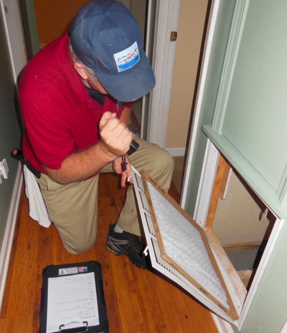
9.4 Installation
9.4.1 Installation shall be in accordance with manufacturer printed instructions.