Heating, ventilation and air conditioning systems (HVAC) is noisy when operation started. When used in hotels and buildings, HVAC systems can be annoying to customers awake or even distract speakers in conference rooms. Although some air conditioners are noisier than others, proper installation of the systems with noise attenuators ensure they run smoothly and produce less noise.
How to define Noise Attenuators?
To reduce the noise transmitted from a source to the receiver. For HVAC applications, they are normally installed on intake and discharge sides of a fan or air handling unit.
Sound Attenuators | Noise Reduction for HVAC Duct Systems
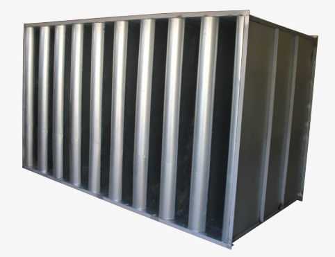
8.1 The sound attenuator shall be fabricated with the outer casing of 22 gauge (minimum) galvanized sheet steel and shall be rectangular or circular, modular construction with acoustic filler enclosed in the center splitter baffles and in the outer side baffles. Interior casing for rectangular silencers shall be 26 gauge perforated galvanized steel. Seams shall be locked formed and mastic filled, airtight construction. There shall be no air leakage or structural deformation when an air pressure differential of 2.0 kPa is imposed across the outer casing.
8.2 The acoustic filler shall be glass fiber, packed under compression to eliminate voids caused by vibration or settling. The filter shall by inert, venin- proof and moisture- proof.
8.3 The fire hazard rating of the filter shall be as follows when tested in accordance with ASTM E 84.
8.4 Acoustical ratings shall be based on duct- to- reverberant room tests providing separate ratings for both forward flow ( silencer on the discharge side of the system fan ) and reverse flow ( silencer on the suction side of the system fan ), with the airflow between- 10.16 and + 10.16 meters per second face velocity. Tests shall be run both with and without air flowing through silencer and at not less than three different flow rates. Ratings shall be published catalog values, factory- certified on printed fronts. Typewritten values on blank forms are not acceptable. The test procedure shall eliminate the effects from and deflection, directivity, flanking transmission, standing waves and test chamber sound absorption.
8.5 Airflow shall be in same direction as attenuation for tests on dynamic insertion loss. Sound power levels shall be measured at downstream end of silencer. Dynamic insertion loss in db shall be less than scheduled below at face velocity of 5.08 mps.
8.6 Tests to determine the aerodynamic ratings shall be in accordance with ASTM E 477 and AMCA 300 and shall be conducted at the same time in the same test facility, and with the same sound attenuator sample employed in all acoustical tests. Airflow and pressure loss measurements shall be made in accordance with applicable portions of ASMS, AMCS and ADC airflow tests.
8.7 Installation shall be in accordance with manufacturer printed instructions.