A payload range diagram, also known as a payload range chart or payload-range graph, is a graphical representation used in aviation to depict the trade-off between an aircraft’s payload (the weight of passengers, cargo, or fuel it can carry) and its range (the distance it can travel without refueling).
Typically, the horizontal axis of the diagram represents the range of the aircraft, usually measured in nautical miles or kilometers, while the vertical axis represents the payload capacity, often measured in weight units such as kilograms or pounds.
Each point on the graph corresponds to a specific combination of payload and range achievable by the aircraft under certain operating conditions, such as fuel load, cruising speed, and altitude. The curve or line connecting these points represents the aircraft’s performance envelope, showing the maximum payload that can be carried for a given range, or conversely, the maximum range achievable for a given payload.
The payload range diagram is an essential tool for aircraft operators, manufacturers, and planners as it helps them understand and optimize the trade-offs between payload capacity and range to meet the requirements of specific missions, such as passenger transport, cargo delivery, or military operations. It also assists in making decisions regarding fuel load, route planning, and payload allocation to maximize the aircraft’s efficiency and profitability.
Weights of the aircraft
The weights of an aircraft are crucial parameters that play a significant role in its performance and operation. Here are the definitions of the different weights:
- Operating Empty Weight (OEW): The OEW is the basic weight of an aircraft, including the crew, all necessary fluids for operation (such as engine oil, coolant, and water), unusable fuel, and all operator items and equipment required for flight. It excludes usable fuel and the payload. OEW also includes certain standard items, personnel, equipment, and supplies necessary for full operation.
- Payload (PL): The payload refers to the load for which the company charges a fee. In transportation aircraft, it includes passengers and their luggage, as well as cargo.
- Fuel Weight (FW): The fuel weight of an aircraft is the total weight of fuel carried at takeoff. It comprises two components:
- Trip Fuel (TF): The estimated total amount of fuel to be consumed during the trip.
- Reserve Fuel (RF): Additional fuel carried to account for unforeseen circumstances, such as inaccurate weather forecasts or the need for alternative arrival airports.
- Takeoff Weight (TOW): The takeoff weight is the total weight of the aircraft at the moment of takeoff. It is calculated as the sum of the operating empty weight, payload, and fuel weight: TOW = OEW + PL + FW.
- Landing Weight (LW): The landing weight of an aircraft is the total weight of the aircraft upon reaching its destination, excluding reserve fuel. LW = OEW + PL + RF.
- Zero Fuel Weight (ZFW): The zero fuel weight is the total weight of the aircraft and all its contents, excluding the weight of the fuel on board. ZFW = OEW + PL.
These weight parameters are essential for flight planning, performance calculations, and ensuring that the aircraft operates within safe limits throughout the flight.
Limitation on the Weight of an Aircraft
Limitations on the weight of an aircraft are essential for ensuring safe operation and compliance with structural and capacity constraints. Here are the limitations on the different weights of an aircraft:
- Maximum Payload (MPL): The maximum payload of an aircraft is restricted by structural limits and capacity constraints. It represents the maximum weight of passengers, cargo, and baggage that can be carried.
- Maximum Fuel Weight (MFW): The maximum fuel weight is determined by the capacity of the fuel tanks. It represents the maximum amount of fuel that can be carried on board the aircraft.
- Maximum Zero Fuel Weight (MZFW): The maximum zero fuel weight is the maximum weight allowed before usable fuel and other specified agents must be loaded. It is limited by strength and airworthiness requirements and may include usable fuel in specified tanks when carried instead of payload.
- Maximum Takeoff Weight (MTOW): The maximum takeoff weight is the maximum weight at which the pilot is allowed to attempt takeoff. It is restricted by structural or other limits to ensure safe takeoff performance.
- Maximum Landing Weight (MLW): The maximum landing weight is the maximum weight at which the pilot is allowed to attempt a landing. It is limited by structural constraints, particularly in the landing gear, to ensure safe landing operations.
These weight limitations are critical for flight planning, performance calculations, and compliance with regulatory requirements to maintain the safety and airworthiness of the aircraft.
Payload Range Diagram
A payload range diagram, commonly known as an elbow chart, offers a graphical depiction of the interplay between an aircraft’s payload capacity and its range. At its core, the diagram features a horizontal line representing the maximum payload, constrained structurally by the maximum zero fuel weight (MZFW) of the aircraft. This maximum payload is calculated as the difference between the MZFW and the operational empty weight (OEW) of the aircraft. Moving along this line from left to right reveals a consistent maximum payload as the range increases, indicating the necessity of adding more fuel to achieve greater distances.
One notable aspect illustrated by the payload-range diagram is the relative significance of weight distribution within the aircraft. While weight in the fuel tanks located in the wings does contribute to the overall load, it does not exert as significant an impact on the wing’s bending moment as weight located in the fuselage. Consequently, even when the aircraft is loaded with its maximum payload supported by the wings, it can still accommodate a substantial amount of fuel.
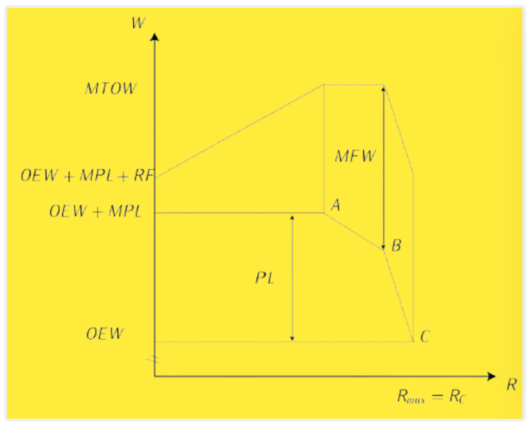
A vertical line on the diagram denotes the range at which the combined weight of the aircraft, maximum payload, and required fuel reaches the maximum takeoff weight (MTOW). Beyond this point, any attempt to extend the range would necessitate sacrificing payload in favor of carrying additional fuel.
The maximum takeoff weight is determined by factors such as the maximum net power of the engines and the lift-to-drag ratio of the wings. Following the point where the range reaches its maximum payload, adjustments can be made to payload levels to allow for increased fuel capacity, thereby expanding the range while taking off at the MTOW.
The presence of a second kink in the curve signifies the point at which the aircraft’s maximum fuel capacity is reached. Beyond this threshold, further increases in range would require a substantial reduction in payload, resulting in diminishing returns in terms of range extension relative to payload sacrifice. Ultimately, the absolute range of the aircraft is defined as the distance it can cover with the maximum possible fuel load and without carrying any payload.
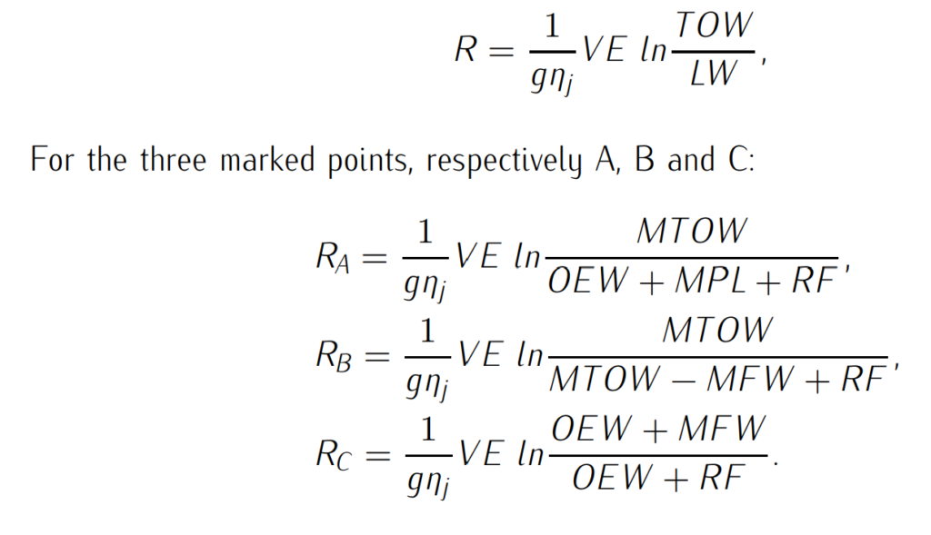
To establish a correlation between ranges and weights, the Breguet equation is often employed, providing a mathematical framework for analyzing the relationship between fuel consumption, aircraft weight, and range.